EP1546598B1 - Method and means for mounting a hose connection to a flexible metal hose comprising a corrugated inner hose surrounded by a braided covering - Google Patents
Method and means for mounting a hose connection to a flexible metal hose comprising a corrugated inner hose surrounded by a braided covering Download PDFInfo
- Publication number
- EP1546598B1 EP1546598B1 EP03761004A EP03761004A EP1546598B1 EP 1546598 B1 EP1546598 B1 EP 1546598B1 EP 03761004 A EP03761004 A EP 03761004A EP 03761004 A EP03761004 A EP 03761004A EP 1546598 B1 EP1546598 B1 EP 1546598B1
- Authority
- EP
- European Patent Office
- Prior art keywords
- hose
- covering
- connection
- support means
- mounting
- Prior art date
- Legal status (The legal status is an assumption and is not a legal conclusion. Google has not performed a legal analysis and makes no representation as to the accuracy of the status listed.)
- Expired - Lifetime
Links
- 238000000034 method Methods 0.000 title claims abstract description 14
- 239000002184 metal Substances 0.000 title claims abstract description 12
- 230000007704 transition Effects 0.000 claims description 8
- 238000005304 joining Methods 0.000 claims description 3
- 238000003466 welding Methods 0.000 claims description 3
- 238000003825 pressing Methods 0.000 description 4
- 238000007789 sealing Methods 0.000 description 4
- 238000005452 bending Methods 0.000 description 3
- 230000006835 compression Effects 0.000 description 2
- 238000007906 compression Methods 0.000 description 2
- 230000008878 coupling Effects 0.000 description 2
- 238000010168 coupling process Methods 0.000 description 2
- 238000005859 coupling reaction Methods 0.000 description 2
- 238000005259 measurement Methods 0.000 description 2
- 238000004026 adhesive bonding Methods 0.000 description 1
- 230000000694 effects Effects 0.000 description 1
- 238000009434 installation Methods 0.000 description 1
- 238000004519 manufacturing process Methods 0.000 description 1
Images



Classifications
-
- F—MECHANICAL ENGINEERING; LIGHTING; HEATING; WEAPONS; BLASTING
- F16—ENGINEERING ELEMENTS AND UNITS; GENERAL MEASURES FOR PRODUCING AND MAINTAINING EFFECTIVE FUNCTIONING OF MACHINES OR INSTALLATIONS; THERMAL INSULATION IN GENERAL
- F16L—PIPES; JOINTS OR FITTINGS FOR PIPES; SUPPORTS FOR PIPES, CABLES OR PROTECTIVE TUBING; MEANS FOR THERMAL INSULATION IN GENERAL
- F16L25/00—Construction or details of pipe joints not provided for in, or of interest apart from, groups F16L13/00 - F16L23/00
- F16L25/0036—Joints for corrugated pipes
-
- F—MECHANICAL ENGINEERING; LIGHTING; HEATING; WEAPONS; BLASTING
- F16—ENGINEERING ELEMENTS AND UNITS; GENERAL MEASURES FOR PRODUCING AND MAINTAINING EFFECTIVE FUNCTIONING OF MACHINES OR INSTALLATIONS; THERMAL INSULATION IN GENERAL
- F16L—PIPES; JOINTS OR FITTINGS FOR PIPES; SUPPORTS FOR PIPES, CABLES OR PROTECTIVE TUBING; MEANS FOR THERMAL INSULATION IN GENERAL
- F16L33/00—Arrangements for connecting hoses to rigid members; Rigid hose-connectors, i.e. single members engaging both hoses
- F16L33/01—Arrangements for connecting hoses to rigid members; Rigid hose-connectors, i.e. single members engaging both hoses specially adapted for hoses having a multi-layer wall
Definitions
- the present invention concerns a means and a method of manufacturing a hose coupling as described in the preamble to claim 1.
- Flexible metal hose has many uses today, such as on installations demanding hoses with high resistance to high pressure, high temperatures and wear.
- the hoses are intended to convey all types of media, such as oil, foodstuffs and the like.
- These hoses are often constructed with a braided metal covering over a corrugated inner hose.
- the braided metal is used to give the hose a higher resistance to pressure inside the hose and to improve its resistance to wear, while the corrugated inner hose can be bent without it folding.
- Hose connections are available in a number of different designs.
- One example is a connection that is screwed directly onto the hose, whereby the corrugated inner hose is folded to obtain a sealing surface. This method, however, has the disadvantage of leaking easily.
- Another example of a connection is a sleeve that is pressed against the inner hose, which is deformed while the braided outer hose is cut level with the said inner hose. Another tool is then used to make a groove in the sleeve. The sleeve and connection is then welded to the folded part of the inner hose.
- This method however, has the disadvantage of requiring several different tools, making it time-consuming and uneconomic.
- a formable ring and a compression tool are placed on a corrugated hose.
- the compression tool comprises an inner and an outer part connected by a screw thread.
- the inner tool part is placed flush with the hose end, with the edge of the ring contacting a beveled edge of the tool.
- the outer tool part is placed on the threads, and when the outer part is turned on the threads the ring is pressed inwardly towards the end of the hose and against one of the corrugations on the hose, whereby a seat is formed. Due to the movement of the ring, no braided metal covering can be used on the hose.
- One object of the present invention is to provide a means and a method of obtaining a seat on the end of a hose onto which the hose connection can be mounted simply, quickly and economically in one single operation.
- This object of the invention can be achieved by mounting the hose in a tool, a means of support in the form of a sleeve that is fitted over the hose, a tool is pressed against the edge of the hose and the sleeve, whereby the hose and the sleeve are pressed together.
- the hose coupling is then welded to the folded part of the inner hose and to the sleeve.
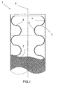
- a flexible hose designated with reference number 1 contains an inner, corrugated metal hose 2.
- corrugated means a wave shaped longitudinal section with troughs 3 and peaks 4, where a trough 3 is defined as the part that is closest to the centre line 5 of the hose 1 and a peak 4 as the part that is farthest away from the centre line 5.
- the transition 6 between a peak 4 and a trough 3 is defined as the part where the hose 2 wall is relatively perpendicular to the centre line 5.
- the corrugated shape is intended to allow bending of the hose 1 without the walls of the hose folding.
- Outside hose 1 is arranged a woven metallic covering 7 in the form of a braid and a means of support 8 outside the covering 7 in the form of a sleeve.
- the metallic covering 7 is intended to protect the corrugated inner hose 2 from wear while it also provides support when bending the hose, prevents the hose from expanding outside its outside diameter when bending and gives the hose an increased compressive strength.
- only the corrugated inner hose 2 is used without the metal covering.
- the function of the support means 8 will be described in more detail below.
- a forming part 11 in the form of a press tool is used to prepare the end of the hose 9.
- the forming part 11 comprises an outer 12 and an inner 13 forming section.
- the outer forming section 12 is an annular wall arranged around the inner forming section 13.
- the annular wall has an inside diameter that is slightly smaller than the outside diameter of the applied support means 8.
- an annular gap 14 is arranged between the annular wall and the inside forming section 13 into which the hose 1 metal covering 7 fits during the pressing phase.
- the inside edge of the free end of the wall is arranged with a bevelled edge 15.
- the larger diameter of the bevelled edge 15 is somewhat larger than the outside diameter of the support means 8.
- the bevelled edge 15 presses in the free end closest to the end of the hose 9 of the applied support means 8 towards the closest peak 4 of the corrugated inner hose, whereby the edge of the support means 8 provides support for the peak 4 during the pressing phase.
- the inner forming section 13 is a cylinder with surrounding wall and bottom surface 16 directed towards the end of the hose 9.
- the transition of the bottom surface to the surrounding wall is at a relatively perpendicular angle.
- the transition is a rounded edge intended to form a rounded flange.
- the inner forming section 13 has an outside diameter that corresponds with the inside diameter of the connection 10 that is applied in the final phase.
- the transition between the bottom surface 16 and the surrounding wall is used partly to form a seat 17 during the pressing phase to which the connection is intended to be arranged and partly to press together the double folded section of the hose to a compact double-walled surface of which one part is used during the final welding.
- connection 10 comprises a tubular part that in this example is finished with a straight edge intended to be arranged to the seat 17 but can be designed in various ways depending on the application for which it is used.
- the welding joins the connection to the finished seat 17, support means 8 and the covering 7.
- a cut is made on the braid 7 and hose 2 at a position where the hose 2 peak 4 changes into a trough 3 in such a way that the cut surface of the remaining end 9 is directed towards the centre line 5 of the hose 2.
- the support means 8 is fitted over the covering 7 as in figure 2 to a position where the free end of the support means 8 closest to the end of the hose comes just beyond the next peak 4 of corrugation after the cut. This will prevent the remaining corrugation of the hose from being affected by the pressing phase.
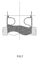
- the forming part 11 is applied to the cut hose 2 as in figure 3 and pressed against the cut surface in the lengthwise direction of the hose 1.
- the outer forming section 12 first contacts the free end of the fitted support means 8 closest to the end of the hose, which is driven inwards towards the centre line 5 of the hose 2 by the bevelled edge 15 of the forming section 12. While the forming part 11 continues to move in the longitudinal direction of the hose 1 as in figure 3 , the support means 8 is gradually driven inwards while the end of the covering 7 is guided into the surrounding gap 14. When the free end of the support means 8 edge closest to the end of the hose is driven inwards, it makes contact with the corrugated peak 4 of the corrugated inner hose 2.
- the flat surface 16 of the inner forming section 13 makes contact with the cut edge of the hose 2, which is pressed in a direction away from the free end of the hose.
- the end 9 of the hose 2 is pressed farther away until the cut surface makes contact with the transition 6 between the next peak 4 and trough 3 as in figure 5 .
- the sudden radial outer section of the hose 2 that is obtained during this movement is pressed past the edge of the forming section 13 out towards the braided covering 7 and the free end of the support means 8 closest to the end of the hose with the sudden radial outer section of the hose 2 supporting the inward driven edge of the fitted support means 8.
- connection 10 is placed in the finished seat 17, thereby making a surrounding shoulder 18 with inside measurement corresponding to the outside measurement of the connection 10.
- a weld run 19 is placed in the said shoulder 18, whereby the connection is joined to the support means 8, covering 7 and inner hose 2.
- the joining of the connection to the seat can be by means of an automatic welder, gluing or other method of joining.
Landscapes
- Engineering & Computer Science (AREA)
- General Engineering & Computer Science (AREA)
- Mechanical Engineering (AREA)
- Joints That Cut Off Fluids, And Hose Joints (AREA)
- Rigid Pipes And Flexible Pipes (AREA)
Applications Claiming Priority (3)
| Application Number | Priority Date | Filing Date | Title |
|---|---|---|---|
| SE0201951A SE524440C2 (sv) | 2002-06-25 | 2002-06-25 | Förfarande och anordning vid montering av en slanganslutning till en flexibel metallslang innefattande en korrugerad innerslang omsluten ev en flätad strumpa |
| SE0201951 | 2002-06-25 | ||
| PCT/SE2003/001089 WO2004001271A1 (en) | 2002-06-25 | 2003-06-24 | Method and means for mounting a hose connection to a flexible metal hose comprising a corrugated inner hose surrounded by a braided covering |
Publications (2)
| Publication Number | Publication Date |
|---|---|
| EP1546598A1 EP1546598A1 (en) | 2005-06-29 |
| EP1546598B1 true EP1546598B1 (en) | 2008-11-26 |
Family
ID=20288309
Family Applications (1)
| Application Number | Title | Priority Date | Filing Date |
|---|---|---|---|
| EP03761004A Expired - Lifetime EP1546598B1 (en) | 2002-06-25 | 2003-06-24 | Method and means for mounting a hose connection to a flexible metal hose comprising a corrugated inner hose surrounded by a braided covering |
Country Status (8)
| Country | Link |
|---|---|
| EP (1) | EP1546598B1 (da) |
| AT (1) | ATE415588T1 (da) |
| AU (1) | AU2003244287A1 (da) |
| DE (1) | DE60324951D1 (da) |
| DK (1) | DK1546598T3 (da) |
| ES (1) | ES2318162T3 (da) |
| SE (1) | SE524440C2 (da) |
| WO (1) | WO2004001271A1 (da) |
Families Citing this family (2)
| Publication number | Priority date | Publication date | Assignee | Title |
|---|---|---|---|---|
| US12031658B2 (en) | 2016-07-15 | 2024-07-09 | Nordson Corporation | Adhesive transfer hose having a barrier layer and method of use |
| CN112388196B (zh) * | 2020-10-26 | 2021-08-13 | 西安交通大学 | 一种波纹金属软管网套压紧环锁紧装置及方法 |
Family Cites Families (4)
| Publication number | Priority date | Publication date | Assignee | Title |
|---|---|---|---|---|
| GB804583A (en) * | 1956-01-06 | 1958-11-19 | Kac Ltd | Improvements relating to corrugated metal tubing and end fittings therefor |
| BE553797A (da) * | 1956-01-13 | |||
| US6092274A (en) * | 1998-02-26 | 2000-07-25 | 40 Properties Management, Ltd | Metal hose fitting and method of making |
| DE20121607U1 (de) * | 2001-12-07 | 2003-01-09 | Witzenmann GmbH, 75175 Pforzheim | Anschlussvorrichtung für einen ringgewellten Metallschlauch |
-
2002
- 2002-06-25 SE SE0201951A patent/SE524440C2/sv not_active IP Right Cessation
-
2003
- 2003-06-24 DK DK03761004T patent/DK1546598T3/da active
- 2003-06-24 WO PCT/SE2003/001089 patent/WO2004001271A1/en not_active Ceased
- 2003-06-24 DE DE60324951T patent/DE60324951D1/de not_active Expired - Lifetime
- 2003-06-24 AT AT03761004T patent/ATE415588T1/de not_active IP Right Cessation
- 2003-06-24 EP EP03761004A patent/EP1546598B1/en not_active Expired - Lifetime
- 2003-06-24 ES ES03761004T patent/ES2318162T3/es not_active Expired - Lifetime
- 2003-06-24 AU AU2003244287A patent/AU2003244287A1/en not_active Abandoned
Also Published As
| Publication number | Publication date |
|---|---|
| SE524440C2 (sv) | 2004-08-10 |
| SE0201951L (sv) | 2003-12-26 |
| ATE415588T1 (de) | 2008-12-15 |
| EP1546598A1 (en) | 2005-06-29 |
| SE0201951D0 (sv) | 2002-06-25 |
| AU2003244287A1 (en) | 2004-01-06 |
| WO2004001271A1 (en) | 2003-12-31 |
| ES2318162T3 (es) | 2009-05-01 |
| DK1546598T3 (da) | 2009-03-16 |
| DE60324951D1 (de) | 2009-01-08 |
Similar Documents
| Publication | Publication Date | Title |
|---|---|---|
| JP4439951B2 (ja) | 波形管体と接続部片との間の結合部を形成するための方法 | |
| EP0939265B1 (en) | Metal hose fitting and method of making | |
| US8308201B2 (en) | Crimp fitting for corrugated stainless steel tubing | |
| US7364206B2 (en) | Compression fitting for pipes | |
| US8888141B2 (en) | Fluid coupling assembly and method of manufacture | |
| EP3594602B1 (en) | Vibration absorption tubing and manufacturing method thereof | |
| US20100253066A1 (en) | Crimp-Type Coupling, Crimping Tool and Method of Crimping | |
| US20100090459A1 (en) | Quick actuating fitting for corrugated stainless steel tubing | |
| US20140361535A1 (en) | Connection assembly | |
| US8727388B2 (en) | Coupling arrangement comprising a coupling body and a metal pipe, as well as method for assembly of the coupling body | |
| EP1546598B1 (en) | Method and means for mounting a hose connection to a flexible metal hose comprising a corrugated inner hose surrounded by a braided covering | |
| US20070013189A1 (en) | Sealing fitting for stainless steel tubing | |
| CN102159865A (zh) | 两件式连接配件 | |
| KR101821649B1 (ko) | 내진용 주름부와 연결조인트를 가진 스테인레스 강관 및 그 제조방법 | |
| JP2005325934A (ja) | フレキシブルメタルホースの端末構造 | |
| CN100419322C (zh) | 非焊接接头金属软管及制作方法 | |
| CN215635576U (zh) | 承插压合管件焊接法兰盘的焊接组件 | |
| KR200321875Y1 (ko) | 압입 결합식 관이음장치 | |
| JP5784301B2 (ja) | 差込式地中埋設鋼管の接続構造 | |
| CN116336280A (zh) | 基于炉中钎焊的波纹金属软管 | |
| JP2008298175A (ja) | 配管の接続構造 | |
| HK1106471B (en) | Method and apparatus for cold joining flanges and couplings elements to pipes | |
| HK1106471A1 (en) | Method and apparatus for cold joining flanges and couplings elements to pipes | |
| JP2010071429A (ja) | フレキシブル継手 |
Legal Events
| Date | Code | Title | Description |
|---|---|---|---|
| PUAI | Public reference made under article 153(3) epc to a published international application that has entered the european phase |
Free format text: ORIGINAL CODE: 0009012 |
|
| 17P | Request for examination filed |
Effective date: 20050124 |
|
| AK | Designated contracting states |
Kind code of ref document: A1 Designated state(s): AT BE BG CH CY CZ DE DK EE ES FI FR GB GR HU IE IT LI LU MC NL PT RO SE SI SK TR |
|
| 17Q | First examination report despatched |
Effective date: 20060717 |
|
| 17Q | First examination report despatched |
Effective date: 20060717 |
|
| GRAP | Despatch of communication of intention to grant a patent |
Free format text: ORIGINAL CODE: EPIDOSNIGR1 |
|
| GRAS | Grant fee paid |
Free format text: ORIGINAL CODE: EPIDOSNIGR3 |
|
| GRAA | (expected) grant |
Free format text: ORIGINAL CODE: 0009210 |
|
| AK | Designated contracting states |
Kind code of ref document: B1 Designated state(s): AT BE BG CH CY CZ DE DK EE ES FI FR GB GR HU IE IT LI LU MC NL PT RO SE SI SK TR |
|
| REG | Reference to a national code |
Ref country code: GB Ref legal event code: FG4D |
|
| REG | Reference to a national code |
Ref country code: CH Ref legal event code: EP |
|
| REG | Reference to a national code |
Ref country code: IE Ref legal event code: FG4D |
|
| REF | Corresponds to: |
Ref document number: 60324951 Country of ref document: DE Date of ref document: 20090108 Kind code of ref document: P |
|
| REG | Reference to a national code |
Ref country code: DK Ref legal event code: T3 |
|
| PG25 | Lapsed in a contracting state [announced via postgrant information from national office to epo] |
Ref country code: AT Free format text: LAPSE BECAUSE OF FAILURE TO SUBMIT A TRANSLATION OF THE DESCRIPTION OR TO PAY THE FEE WITHIN THE PRESCRIBED TIME-LIMIT Effective date: 20081126 |
|
| REG | Reference to a national code |
Ref country code: ES Ref legal event code: FG2A Ref document number: 2318162 Country of ref document: ES Kind code of ref document: T3 |
|
| NLV1 | Nl: lapsed or annulled due to failure to fulfill the requirements of art. 29p and 29m of the patents act | ||
| PG25 | Lapsed in a contracting state [announced via postgrant information from national office to epo] |
Ref country code: SI Free format text: LAPSE BECAUSE OF FAILURE TO SUBMIT A TRANSLATION OF THE DESCRIPTION OR TO PAY THE FEE WITHIN THE PRESCRIBED TIME-LIMIT Effective date: 20081126 Ref country code: NL Free format text: LAPSE BECAUSE OF FAILURE TO SUBMIT A TRANSLATION OF THE DESCRIPTION OR TO PAY THE FEE WITHIN THE PRESCRIBED TIME-LIMIT Effective date: 20081126 |
|
| PG25 | Lapsed in a contracting state [announced via postgrant information from national office to epo] |
Ref country code: EE Free format text: LAPSE BECAUSE OF FAILURE TO SUBMIT A TRANSLATION OF THE DESCRIPTION OR TO PAY THE FEE WITHIN THE PRESCRIBED TIME-LIMIT Effective date: 20081126 Ref country code: BG Free format text: LAPSE BECAUSE OF FAILURE TO SUBMIT A TRANSLATION OF THE DESCRIPTION OR TO PAY THE FEE WITHIN THE PRESCRIBED TIME-LIMIT Effective date: 20090226 Ref country code: RO Free format text: LAPSE BECAUSE OF FAILURE TO SUBMIT A TRANSLATION OF THE DESCRIPTION OR TO PAY THE FEE WITHIN THE PRESCRIBED TIME-LIMIT Effective date: 20081126 Ref country code: BE Free format text: LAPSE BECAUSE OF FAILURE TO SUBMIT A TRANSLATION OF THE DESCRIPTION OR TO PAY THE FEE WITHIN THE PRESCRIBED TIME-LIMIT Effective date: 20081126 |
|
| PG25 | Lapsed in a contracting state [announced via postgrant information from national office to epo] |
Ref country code: PT Free format text: LAPSE BECAUSE OF FAILURE TO SUBMIT A TRANSLATION OF THE DESCRIPTION OR TO PAY THE FEE WITHIN THE PRESCRIBED TIME-LIMIT Effective date: 20090427 Ref country code: SE Free format text: LAPSE BECAUSE OF FAILURE TO SUBMIT A TRANSLATION OF THE DESCRIPTION OR TO PAY THE FEE WITHIN THE PRESCRIBED TIME-LIMIT Effective date: 20090226 Ref country code: CZ Free format text: LAPSE BECAUSE OF FAILURE TO SUBMIT A TRANSLATION OF THE DESCRIPTION OR TO PAY THE FEE WITHIN THE PRESCRIBED TIME-LIMIT Effective date: 20081126 |
|
| PG25 | Lapsed in a contracting state [announced via postgrant information from national office to epo] |
Ref country code: SK Free format text: LAPSE BECAUSE OF FAILURE TO SUBMIT A TRANSLATION OF THE DESCRIPTION OR TO PAY THE FEE WITHIN THE PRESCRIBED TIME-LIMIT Effective date: 20081126 |
|
| PLBE | No opposition filed within time limit |
Free format text: ORIGINAL CODE: 0009261 |
|
| STAA | Information on the status of an ep patent application or granted ep patent |
Free format text: STATUS: NO OPPOSITION FILED WITHIN TIME LIMIT |
|
| 26N | No opposition filed |
Effective date: 20090827 |
|
| PG25 | Lapsed in a contracting state [announced via postgrant information from national office to epo] |
Ref country code: MC Free format text: LAPSE BECAUSE OF NON-PAYMENT OF DUE FEES Effective date: 20090630 |
|
| REG | Reference to a national code |
Ref country code: CH Ref legal event code: PL |
|
| PG25 | Lapsed in a contracting state [announced via postgrant information from national office to epo] |
Ref country code: LI Free format text: LAPSE BECAUSE OF NON-PAYMENT OF DUE FEES Effective date: 20090630 Ref country code: IE Free format text: LAPSE BECAUSE OF NON-PAYMENT OF DUE FEES Effective date: 20090624 Ref country code: CH Free format text: LAPSE BECAUSE OF NON-PAYMENT OF DUE FEES Effective date: 20090630 |
|
| PG25 | Lapsed in a contracting state [announced via postgrant information from national office to epo] |
Ref country code: GR Free format text: LAPSE BECAUSE OF FAILURE TO SUBMIT A TRANSLATION OF THE DESCRIPTION OR TO PAY THE FEE WITHIN THE PRESCRIBED TIME-LIMIT Effective date: 20090227 |
|
| PG25 | Lapsed in a contracting state [announced via postgrant information from national office to epo] |
Ref country code: LU Free format text: LAPSE BECAUSE OF NON-PAYMENT OF DUE FEES Effective date: 20090624 |
|
| PG25 | Lapsed in a contracting state [announced via postgrant information from national office to epo] |
Ref country code: HU Free format text: LAPSE BECAUSE OF FAILURE TO SUBMIT A TRANSLATION OF THE DESCRIPTION OR TO PAY THE FEE WITHIN THE PRESCRIBED TIME-LIMIT Effective date: 20090527 |
|
| PG25 | Lapsed in a contracting state [announced via postgrant information from national office to epo] |
Ref country code: TR Free format text: LAPSE BECAUSE OF FAILURE TO SUBMIT A TRANSLATION OF THE DESCRIPTION OR TO PAY THE FEE WITHIN THE PRESCRIBED TIME-LIMIT Effective date: 20081126 |
|
| PG25 | Lapsed in a contracting state [announced via postgrant information from national office to epo] |
Ref country code: CY Free format text: LAPSE BECAUSE OF FAILURE TO SUBMIT A TRANSLATION OF THE DESCRIPTION OR TO PAY THE FEE WITHIN THE PRESCRIBED TIME-LIMIT Effective date: 20081126 |
|
| REG | Reference to a national code |
Ref country code: FR Ref legal event code: PLFP Year of fee payment: 14 |
|
| REG | Reference to a national code |
Ref country code: FR Ref legal event code: PLFP Year of fee payment: 15 |
|
| REG | Reference to a national code |
Ref country code: FR Ref legal event code: PLFP Year of fee payment: 16 |
|
| PGFP | Annual fee paid to national office [announced via postgrant information from national office to epo] |
Ref country code: DE Payment date: 20180612 Year of fee payment: 16 Ref country code: FI Payment date: 20180612 Year of fee payment: 16 Ref country code: DK Payment date: 20180612 Year of fee payment: 16 |
|
| PGFP | Annual fee paid to national office [announced via postgrant information from national office to epo] |
Ref country code: FR Payment date: 20180514 Year of fee payment: 16 |
|
| PGFP | Annual fee paid to national office [announced via postgrant information from national office to epo] |
Ref country code: GB Payment date: 20180620 Year of fee payment: 16 Ref country code: ES Payment date: 20180702 Year of fee payment: 16 Ref country code: IT Payment date: 20180625 Year of fee payment: 16 |
|
| REG | Reference to a national code |
Ref country code: DE Ref legal event code: R082 Ref document number: 60324951 Country of ref document: DE Representative=s name: TERGAU & WALKENHORST PATENTANWAELTE PARTGMBB, DE |
|
| REG | Reference to a national code |
Ref country code: DE Ref legal event code: R119 Ref document number: 60324951 Country of ref document: DE |
|
| REG | Reference to a national code |
Ref country code: FI Ref legal event code: MAE |
|
| REG | Reference to a national code |
Ref country code: DK Ref legal event code: EBP Effective date: 20190630 |
|
| PG25 | Lapsed in a contracting state [announced via postgrant information from national office to epo] |
Ref country code: FI Free format text: LAPSE BECAUSE OF NON-PAYMENT OF DUE FEES Effective date: 20190624 |
|
| GBPC | Gb: european patent ceased through non-payment of renewal fee |
Effective date: 20190624 |
|
| PG25 | Lapsed in a contracting state [announced via postgrant information from national office to epo] |
Ref country code: GB Free format text: LAPSE BECAUSE OF NON-PAYMENT OF DUE FEES Effective date: 20190624 Ref country code: IT Free format text: LAPSE BECAUSE OF NON-PAYMENT OF DUE FEES Effective date: 20190624 Ref country code: DE Free format text: LAPSE BECAUSE OF NON-PAYMENT OF DUE FEES Effective date: 20200101 |
|
| PG25 | Lapsed in a contracting state [announced via postgrant information from national office to epo] |
Ref country code: FR Free format text: LAPSE BECAUSE OF NON-PAYMENT OF DUE FEES Effective date: 20190630 |
|
| PG25 | Lapsed in a contracting state [announced via postgrant information from national office to epo] |
Ref country code: DK Free format text: LAPSE BECAUSE OF NON-PAYMENT OF DUE FEES Effective date: 20190630 |
|
| REG | Reference to a national code |
Ref country code: ES Ref legal event code: FD2A Effective date: 20201028 |
|
| PG25 | Lapsed in a contracting state [announced via postgrant information from national office to epo] |
Ref country code: ES Free format text: LAPSE BECAUSE OF NON-PAYMENT OF DUE FEES Effective date: 20190625 |