EP1545022B1 - Rückkopplungsentzerrer, zwischenverstärker und verfahren zur rückkopplungsentzerrung - Google Patents
Rückkopplungsentzerrer, zwischenverstärker und verfahren zur rückkopplungsentzerrung Download PDFInfo
- Publication number
- EP1545022B1 EP1545022B1 EP03748705A EP03748705A EP1545022B1 EP 1545022 B1 EP1545022 B1 EP 1545022B1 EP 03748705 A EP03748705 A EP 03748705A EP 03748705 A EP03748705 A EP 03748705A EP 1545022 B1 EP1545022 B1 EP 1545022B1
- Authority
- EP
- European Patent Office
- Prior art keywords
- section
- transmission path
- output
- path characteristic
- loop interference
- Prior art date
- Legal status (The legal status is an assumption and is not a legal conclusion. Google has not performed a legal analysis and makes no representation as to the accuracy of the status listed.)
- Expired - Lifetime
Links
Images


Classifications
-
- H—ELECTRICITY
- H04—ELECTRIC COMMUNICATION TECHNIQUE
- H04B—TRANSMISSION
- H04B7/00—Radio transmission systems, i.e. using radiation field
- H04B7/14—Relay systems
- H04B7/15—Active relay systems
- H04B7/155—Ground-based stations
- H04B7/15564—Relay station antennae loop interference reduction
- H04B7/15585—Relay station antennae loop interference reduction by interference cancellation
-
- H—ELECTRICITY
- H04—ELECTRIC COMMUNICATION TECHNIQUE
- H04B—TRANSMISSION
- H04B3/00—Line transmission systems
- H04B3/02—Details
- H04B3/20—Reducing echo effects or singing; Opening or closing transmitting path; Conditioning for transmission in one direction or the other
- H04B3/23—Reducing echo effects or singing; Opening or closing transmitting path; Conditioning for transmission in one direction or the other using a replica of transmitted signal in the time domain, e.g. echo cancellers
-
- H—ELECTRICITY
- H04—ELECTRIC COMMUNICATION TECHNIQUE
- H04H—BROADCAST COMMUNICATION
- H04H20/00—Arrangements for broadcast or for distribution combined with broadcast
- H04H20/02—Arrangements for relaying broadcast information
- H04H20/06—Arrangements for relaying broadcast information among broadcast stations
-
- H—ELECTRICITY
- H04—ELECTRIC COMMUNICATION TECHNIQUE
- H04H—BROADCAST COMMUNICATION
- H04H20/00—Arrangements for broadcast or for distribution combined with broadcast
- H04H20/65—Arrangements characterised by transmission systems for broadcast
- H04H20/67—Common-wave systems, i.e. using separate transmitters operating on substantially the same frequency
-
- H—ELECTRICITY
- H04—ELECTRIC COMMUNICATION TECHNIQUE
- H04L—TRANSMISSION OF DIGITAL INFORMATION, e.g. TELEGRAPHIC COMMUNICATION
- H04L25/00—Baseband systems
- H04L25/02—Details ; arrangements for supplying electrical power along data transmission lines
- H04L25/0202—Channel estimation
- H04L25/0204—Channel estimation of multiple channels
-
- H—ELECTRICITY
- H04—ELECTRIC COMMUNICATION TECHNIQUE
- H04L—TRANSMISSION OF DIGITAL INFORMATION, e.g. TELEGRAPHIC COMMUNICATION
- H04L25/00—Baseband systems
- H04L25/02—Details ; arrangements for supplying electrical power along data transmission lines
- H04L25/0202—Channel estimation
- H04L25/0224—Channel estimation using sounding signals
- H04L25/0228—Channel estimation using sounding signals with direct estimation from sounding signals
- H04L25/023—Channel estimation using sounding signals with direct estimation from sounding signals with extension to other symbols
- H04L25/0232—Channel estimation using sounding signals with direct estimation from sounding signals with extension to other symbols by interpolation between sounding signals
-
- H—ELECTRICITY
- H04—ELECTRIC COMMUNICATION TECHNIQUE
- H04L—TRANSMISSION OF DIGITAL INFORMATION, e.g. TELEGRAPHIC COMMUNICATION
- H04L5/00—Arrangements affording multiple use of the transmission path
- H04L5/003—Arrangements for allocating sub-channels of the transmission path
- H04L5/0048—Allocation of pilot signals, i.e. of signals known to the receiver
Definitions
- the present invention relates to a loop interference canceller which cancels loop interference using a transmission path characteristic estimated from an OFDM (Orthogonal Frequency Division Multiplexing) signal, and more particularly, to a loop interference canceller, relay system and loop interference canceling method which speeds up an adaptive operation of the loop interference canceller by reducing the number of processed data pieces, realizes high trackability with respect to time variations of the phase and level of a loop interference wave and key station wave, carries out internal processing at a higher degree of accuracy, and can thereby carry out high accuracy cancellation operation and realize miniaturization of the apparatus with a reduced circuit scale.
- OFDM Orthogonal Frequency Division Multiplexing
- the OFDM transmission scheme is a scheme whereby many carriers orthogonal to one another are modulated by digital data transmitted, those modulated signals are multiplexed and transmitted.
- the OFDM transmission scheme is characterized in that increasing the number of carriers used to several hundreds or several thousands extends the symbol time extremely and further adding a replica of a signal of the last part of an effective symbol period before the effective symbol period as a guard period signal makes the signal less susceptible to delay signals.
- Realizing a broadcast wave relay SFN involves the possibility of causing deterioration of the quality of the relay signal and problems of oscillation, etc., of an amplifier because of a phenomenon of radio waves emitted from a transmission antenna wrapping around a reception antenna.
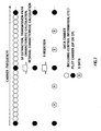
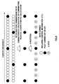
- FIG.1 is a schematic view of an example of an arrangement of pilot signals and shows an arrangement of pilot signals used in DVB-T (Digital Video Broadcasting - Terrestrial) scheme which is a European terrestrial digital broadcasting scheme and ISDB-T (Integrated Services Digital Broadcasting- Terrestrial) scheme which is a Japanese terrestrial digital broadcasting scheme.
- DVB-T Digital Video Broadcasting - Terrestrial
- ISDB-T Integrated Services Digital Broadcasting- Terrestrial
- White circles in FIG.1 represent data carriers and black circles represent pilot carriers (SP: Scattered Pilot) which are scatteringly arranged.
- SP Scattered Pilot
- k on the horizontal axis denotes a carrier number and n on the vertical axis (time axis) denotes a symbol number.
- “mod” in the expression denotes a calculation of a remainder and "p” denotes a non-negative integer.
- kp 3 n mod 4 + 12 ⁇ p
- the SP signal is modulated based on a pseudo-random code string, the amplitude and phase thereof are determined by only the carrier number k arranged and do not depend on the symbol number n. How to determine the amplitude and phase is not important to this explanation and will be omitted, but it is determined by the remainder of 4 of the symbol number n as in the case of the carrier number of the SP.
- pilot signals are placed independently of symbol numbers.
- This pilot signal is also modulated based on a pseudo-random code string and the amplitude and phase thereof are determined by the remainder of 4 of the symbol number n.
- this pilot signal also follows (Expression 1), and therefore hereafter, pilot signals will also be included in the definition pilot carriers or SP.
- FIG.2 is a block diagram showing a configuration example of a loop interference canceller 3.
- a transmission path characteristic estimation section 331 estimates a transmission path characteristic F( ⁇ ) from an output s (t) of a subtractor 31 and the output is supplied to an input of a residual characteristic calculation circuit 3309.
- an FFT First Fourier Transform circuit 3301 extracts a signal whose length corresponds to an effective symbol period from the output s(t) of the subtractor 31, applies an FFT to thereby transform s(t) which is a signal in a time domain into a signal in a frequency domain and the output s( ⁇ ) is supplied to an input of a symbol number extraction circuit 3302 and a first input of an SP extraction circuit 3303.
- FFT First Fourier Transform
- the symbol number extraction circuit 3302 extracts a symbol number for specifying the carrier number of SP from information on symbols such as TMCC (Transmission Multiplexing Configuration Control) included in the input s( ⁇ ). After symbol numbers are extracted once, adding the symbol numbers may also substitute for extraction processing. The remainder of 4 of the symbol number which is minimum information necessary to specify the carrier number, amplitude and phase of SP is output and the output is supplied to the respective second inputs of the SP extraction circuit 3303, a transmission path characteristic calculation circuit 3304 and an SP combination circuit 3305.
- the symbol number will no longer be used directly, and therefore the remainder of 4 of the symbol number will be renamed a "symbol number.”
- the SP extraction circuit 3303 extracts a signal Sp( ⁇ ) of only the SP signal from the output s ( ⁇ ) of the FFT circuit 3301 and the output Sp ( ⁇ ) is supplied to a first input of a transmission path characteristic calculation circuit.
- the transmission path characteristic calculation circuit 3304 generates a specified SP signal Xp( ⁇ ) whose amplitude and phase are known inside, divides the SP signal Sp( ⁇ ) which is the output of the SP extraction circuit 3303 by the Xp( ⁇ ) to calculate a transmission path characteristic Fp( ⁇ ) with respect to SP and the output is supplied to a first input of the SP combination circuit 3305.
- the SP combination circuit 3305 stores transmission path characteristic Fp ( ⁇ ) corresponding to four symbols for the SP, combines the SP distributed to the four symbols into the original arrangement of carriers according to the instruction of the symbol number extraction circuit 3302 and newly outputs a transmission path characteristic Fp'( ⁇ ) corresponding to the combined SP. That is, it rearranges carriers in order of left end of Fp( ⁇ ) with symbol number 0, left end of Fp( ⁇ ) with symbol number 1, left end of Fp( ⁇ ) with symbol number 2, left end of Fp( ⁇ ) with symbol number 3, second from the left end of Fp ( ⁇ ) with symbol number 0, ....
- the transmission path characteristic Fp'( ⁇ ) with respect to the combined SP which is the output is supplied to interpolation circuit 3306.
- the interpolation circuit 3306 interpolates the transmission path characteristic Fp'( ⁇ ) scatteringly obtained with respect to the combined SP and estimates a transmission path characteristic for the entire signal band.
- the interpolation circuit 3306 interpolates the transmission path characteristic at the positions of data carriers deleted from between SPs and obtains a transmission path characteristic for the entire signal band using the transmission path characteristic for the already calculated SP.
- interpolation there may be various possible methods for interpolation such as a method of applying a low pass filter in the carrier direction. This method realizes interpolation by carrying out a convolutional calculation according to an impulse response of the low pass filter. However, from the standpoint of accuracy and stability, the impulse response cannot be helped but be set to a finite length.
- the interpolation circuit 3306 outputs the transmission path characteristic for the entire signal band obtained and the output is supplied to a decimating circuit 3308.
- the decimating circuit 3308 decimates data and reduces the number of data pieces to shorten the processing time in the subsequent circuits.
- the decimating processing is carried out in such a way as to prevent the phase relationship from being shifted by the transform into the time axis at the IFFT circuit 3310 and prevent the position of carrier data which becomes a central frequency of IFFT processing from being shifted.
- data is decimated for every power of 2 in the number of data pieces.
- the number of data pieces decreases as the decimating interval increases, but as described in the Unexamined Japanese Patent Publication No. 2001-223663 , there is a practical limit and it is limited to approximately 2 or 4.
- the decimating circuit can be omitted.
- the data F( ⁇ ) after the decimating is output from the transmission path characteristic estimation section 331 and the output is supplied to the residual characteristic calculation circuit 3309.
- FIG.3 schematically expresses the internal operation of the transmission path characteristic estimation section 331. The operation has already been explained, and therefore the figure will be used only for reference and explanations thereof will be omitted.
- the residual characteristic calculation circuit 3309 calculates a cancellation residual E( ⁇ ) from the output F(w) of the transmission path characteristic estimation section 331 and the output is supplied to the IFFT circuit 3310.
- the IFFT circuit 3310 carries out an IFFT on the output E( ⁇ ) of the residual characteristic calculation circuit 3309 to thereby transform a residual E( ⁇ ) in the frequency domain into a residual e (t) in the time domain and the output is supplied to a factor updating circuit 3311.
- the factor updating circuit 3311 calculates a filter factor w_new(t) from the output e(t) of the IFFT circuit 3310 based on a predetermined factor updating expression and the output is supplied as the output w_fir(t) of the filter factor generation section 33 to a second input of a FIR filter 32.
- the output F( ⁇ ) of the transmission path characteristic estimation section 331 is expressed by (Expression 2).
- F ⁇ w_in ⁇ 1 - w_in ⁇ ⁇ w_o ut ⁇ ⁇ w_loo p ⁇ - w_fir ⁇
- the factor updating expression at the factor updating circuit 3311 is defined by (Expression 8).
- w_new t w_old t + ⁇ e t
- w_old(t) in (Expression 8) is a factor before updating and ⁇ is a non-negative constant of 1 or below.
- feedback control operates so that the cancellation residual E( ⁇ ) which is a difference between the loop interference transfer function w_loop( ⁇ )w_out( ⁇ ) and transfer function w_fir( ⁇ ) of the FIR filter 32 converges to 0 and only the key station wave component is output to the output s(t) of the loop interference canceller 3.
- FIG.4 is a block diagram in which annotations are made on the number of data pieces processed at various sections of the loop interference canceller 3. Connections in the respective sections and their processing are completely the same as those in FIG.2 , and therefore explanations of their operations will be omitted.
- the number of data pieces applies to the case of the transfer in mode 3 of the aforementioned ISDB-T scheme.
- the number of data pieces is 8192.
- the number of data pieces is 469 which is the number of SPs included in one symbol.
- the number of data pieces is 1873 which is the number of SPs corresponding to four symbols (however, the pilot at the right end is common).
- the number of data pieces represents a carrier allocation, and therefore it is 8192 in the same way as the input/output of the FFT circuit 3301.
- the input/output of the residual characteristic calculation circuit 3309 and the input/output of the IFFT circuit 3310 the number of data pieces changes according to how data is reduced by the decimating processing, but it is the same number of data pieces and realistically 2048 or 4096 or 8192.
- This loop interference canceller is required to provide high trackability with respect to time variations of the phase and level of a loop interference wave or key station wave, high accuracy cancellation operation and miniaturization of the apparatus.
- the transmission path characteristic of the entire signal band is estimated through interpolation on the transmission path characteristic by SPs first and then the residual characteristic is calculated, and therefore the number of data pieces increases, which prevents high-speed processing, and moreover the incompleteness of the impulse response of a low pass filter used for interpolation (e.g., finite length) reduces the estimation accuracy of the transmission path characteristic and there is also a problem that the low pass filter requires a large circuit scale.
- US 2002/0039383 (04-04-2002 ) is an example of correction of coupling in SFN
- a subject of the present invention is to calculate a residual characteristic on the transmission path characteristic by a combined SP (Scattered Pilot) and then applying IFFT processing to the residual characteristic to which Os are inserted to transform it into a time domain signal and then carrying out windowing instead of calculating the residual characteristic on the transmission path characteristic by the combined SP after interpolation processing and transforming the residual characteristic to the time domain signal through IFFT processing.
- SP Systemcattered Pilot
- the loop interference canceller is a loop interference canceller for canceling loop interference between transmission/reception antennas when multicarrier signals having reference carriers at regular intervals are relayed at the same frequency for transmission and reception, comprising a cancellation section that cancels loop interference included in a received signal using a filter for which a factor is set, a transmission path characteristic estimation section that estimates the transmission path characteristic of a signal after the loop interference is canceled, a residual characteristic calculation section that calculates a cancellation residual based on the estimation result of the transmission path estimation section, a 0 insertion section that inserts 0 data for the output of the residual characteristic calculation section, an inverse fast Fourier transform section that transforms the output of the 0 insertion section into a time domain signal, a windowing section that extracts either a range of the repetitive component of the transmission path characteristic with respect to the output of the inverse fast Fourier transform section or a range specified by the factor of the filter, whichever is smaller, and an updating section that updates the factor of the filter based on the output
- the loop interference canceling method is a loop interference canceling method for canceling loop interference between transmission/reception antennas when multicarrier signals having reference carriers at regular intervals are relayed at the same frequency for transmission and reception, comprising a canceling step of canceling loop interference included in a received signal using a filter for which a factor is set, a transmission path characteristic estimating step of estimating the transmission path characteristic of a signal after the loop interference is canceled, a residual characteristic calculating step of calculating calculating a cancellation residual based on the estimation result of the transmission path estimation section, a 0 inserting step of inserting 0 data for the output result of the residual characteristic calculation step, an inverse fast Fourier transforming step of transforming the output result of the 0 insertion step into a time domain signal, a windowing step of extracting either a range of the repetitive component of the transmission path characteristic with respect to the output of the inverse fast Fourier transform step or a range specified by the factor of the filter, whichever is smaller, andanupdating step of
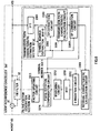
- FIG.5 is a block diagram showing a model of an SFN relay system using a loop interference canceller.
- Symbol "*" in the figure denotes a convolutional calculation.
- signals or responses will be handled as complex numbers hereafter unless otherwise specified.
- (t) denotes a signal in the time domain
- ( ⁇ ) denotes a signal in the frequency domain, and when a signal is defined in one domain, it is also defined in the other domain simultaneously.
- the reception section 2 in FIG.5 converts a signal in an RF (Radio Frequency) band to a baseband signal, while the transmission section 4 contrarily converts a baseband signal to an RF band signal.
- RF Radio Frequency
- x(t) denotes a key station signal
- r(t) denotes an input signal of the reception section 2
- s (t) denotes an input signal of the transmission section 4
- w_in(t) denotes an impulse response of the reception section 2
- w_out(t) denotes an impulse response of the transmission section 4
- w_loop(t) denotes an impulse response of the loop interference transmission path 6
- w_fir(t) denotes an impulse response of an FIR (Finite Impulse Response) filter 32 inside a loop interference canceller 3a.
- FIR Finite Impulse Response
- a reception antenna 1 receives a signal combining the key station signal x(t) and loop interference signal w_loop(t)*w_out(t)*s(t) from the loop interference transmission path and the output r(t) is supplied to the reception section 2.
- the reception section 2 carries out processing such as filtering, frequency conversion and gain adjustment, etc., on the received signal r(t) and the output w_in(t)*r(t) is supplied to a first input of a subtractor 31 in the loop interference canceller 3a.
- the subtractor 31 subtracts the output w_fir(t)*s(t) of the FIR filter 32 from the output w_in(t)*r(t) of the reception section 2 and the output s(t) is supplied to the first input of the FIR filter 32 and filter factor generation section 33 and at the same time, supplied to the transmission section 4 as the output of the loop interference canceller 3a.
- the filter factor generation section 33 estimates the characteristic of the transmission path from the output s(t) of the subtractor 31 to generate a filter factor and the output w_fir(t) is supplied to a second input of the FIR filter 32.
- the FIR filter 32 carries out a convolutional calculation by the output w_fir(t) of the filter factor generation section 33 on the output s (t) of the subtractor 31 to generate a replica w_fir(t)*s(t) of the loop interference signal and the output is supplied to a second input of the subtractor 31.
- the transmission section 4 carries out processing such as filtering, frequency conversion and gain adjustment on the output s(t) of the subtractor 31 to generate a relay signal w_out(t)*s(t) and the output is supplied to a transmission antenna 5.
- the transmission antenna 5 emits the output w_out(t)*s(t) of the transmission section 4 and part of the output is passed through the loop interference transmission path 6 and then wrapped around the reception antenna 1 as the loop interference signal w_loop(t)*w_out(t)*s(t).
- output Fp'( ⁇ ) of the transmission path characteristic estimation section 331a is expressed by (Expression 9). Note that for the OFDM as a whole, not only SP but the outputs of all data carriers are expressed by F( ⁇ ) as shown in (Expression 2), and as in the case of this embodiment, the output at only the frequency of the pilot carriers (SP) is expressed by Fp( ⁇ ). Then, this output Fp( ⁇ ) expresses the output of one symbol and when a plurality of symbols is combined, it is expressed by Fp'( ⁇ ).
- Fp ⁇ w_in ⁇ 1 - w_in ⁇ ⁇ w_o ut ⁇ ⁇ w_loo p ⁇ - w_fir ⁇
- the factor updating circuit 3311 defines the factor updating expression as (Expression 15).
- w_new t w_old t + ⁇ e t
- w_old(t) in (Expression 15) is a factor before updating
- ⁇ is a non-negative constant of 1 or below.
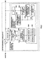
- FIG.6 is a block diagram showing a configuration of the loop interference canceller 3a according to embodiment of the present invention.
- the same components as those in FIG.2 will be explained with the same reference numerals assigned.
- a transmission path characteristic estimation section 331a regards the transmission path characteristic F ( ⁇ ) estimated from the output s(t) of the subtractor 31 as a first output and the output is supplied to the input of a residual characteristic calculation circuit 3309.
- the transmission path characteristic estimation section 331a regards the symbol number which is the minimum information necessary to specify the carrier number, amplitude and phase of SP as the second output, and the output is supplied to the respective second inputs of a 0 insertion circuit 3312 and a phase rotation compensation circuit 3314.
- an FFT (First Fourier Transform) circuit 3301 extracts a signal corresponding to the effective symbol period from the output s(t) of the subtractor 31, carries out an FFT to transform the s(t) which is a time domain signal into a frequency domain signal and the output s( ⁇ ) is supplied to the input of a symbol number extraction circuit 3302 and the first input of an SP extraction circuit 3303.
- FFT First Fourier Transform
- the symbol number extraction circuit 3302 extracts symbol numbers for specifying the arrangement of SPs from the information on symbols such as TMCC (Transmission Multiplexing Configuration Control) included in the inputs( ⁇ ). Once symbol numbers are extracted, adding up the symbol numbers can also substitute for the extraction processing. The remainder of 4 of the symbol number which is the minimum information necessary to specify the carrier number, amplitude and phase of SP is output and the output is supplied to the respective second inputs of the SP extraction circuit 3303, transmission path characteristic calculation circuit 3304, SP combination circuit 33051, 0 insertion circuit 3312 and phase rotation compensation circuit 3314.
- symbol numbers will not be directly used, and therefore the remainder of 4 of the symbol number will be renamed a "symbol number.”
- the SP extraction circuit 3303 extracts the signal Sp ( ⁇ ) of the only SP signal from the output S( ⁇ ) of the FFT circuit 3301 and the output Sp( ⁇ ) is supplied to the first input of the transmission path characteristic calculation circuit 3304.
- the transmission path characteristic calculation circuit 3304 generates a specified SP signal Xp( ⁇ ) whose amplitude and phase are known inside and divides the SP signal Sp( ⁇ ) which is the output of the SP extraction circuit 3303 by the SP signal Xp( ⁇ ) to thereby obtain the transmission path characteristic Fp( ⁇ ) with respect to SP and the output is supplied to the first input of the SP combination circuit 33051.
- the SP combination circuit 33051 stores the transmission path characteristic Fp( ⁇ ) for SPs for a plurality of symbols, combines SPs distributed to a plurality of symbols at the positions of the original carriers according to the specification of the symbol number extraction circuit 3302 according to a rule R specified beforehand and newly outputs the transmission path characteristic Fp'( ⁇ ) for the combined SP.
- the rule R will be explained in more detail later.
- the output Fp'( ⁇ ) of this SP combination circuit 33051 is used as the first output of the transmission path characteristic estimation section 331a and the output is supplied to the residual characteristic calculation circuit 3309.
- the residual characteristic calculation circuit 3309 calculates the cancellation residual E( ⁇ ) from the output Fp'( ⁇ ) of the transmission path characteristic estimation section 331a, uses the calculated cancellation residual E( ⁇ ) as the output and the output is supplied to the first input of the 0 insertion circuit 3312.
- the 0 insertion circuit 3312, IFFT circuit 3310, windowing circuit 3313 and phase rotation compensation circuit 3314 convert the cancellation residual E( ⁇ ) supplied to the first input of the 0 insertion circuit 3312 to a time domain signal e(t) while interpolating characteristics among SPs.
- the 0 insertion circuit 3312 inserts Os at the positions of the data carriers deleted from between cancellation residuals E( ⁇ ) of the combined SP which is the first input.
- the way how to insert Os depends on the rule R. In short, two 0s are inserted at a time. The rule R will be explained in more detail later.
- the 0 insertion circuit 3312 inserts Os at the positions of the data carriers deleted from among the combined SPs. That is, since the combined SPs are arranged every three carriers, two Os are inserted at a time (see interpolation processing in FIG.3 ).
- the number of data pieces needs to be set to power of 2 so as to be handled by the IFFT circuit 3310 that follows and consecutive Os are inserted to the right and left of the data outside the signal band. These insertions also depend on the rule R. In short, the data is expanded by inserting Os so that the band has the same width as that of the signal band handled by the FFT circuit 3301.
- the output of the 0 insertion circuit 3312 with these 0s inserted is supplied to the IFFT circuit 3310.
- the IFFT circuit 3310 carries out an IFFT on the cancellation residual E( ⁇ ) with 0s inserted by the 0 insertion circuit 3312 and thereby transforms the residual E ( ⁇ ) in the frequency domain into the residual e( ⁇ ) in the time domain, and therefore the output is supplied to the windowing circuit 3313.
- the windowing circuit 3313 extracts a range to remove repetitive components of the transmission path characteristic from the time domain signal which is the output of the IFFT circuit 3310 according to the rule R or a range to limit the time domain signal to within the range of factors of the FIR filter 32, whichever is smaller.
- the rule R will be explained in more detail later.
- the output of the windowing circuit 3313 is supplied to the first input of the phase rotation compensation circuit 3314.
- the phase rotation compensation circuit 3314 compensates the phase rotation caused by a shift of the position of the carrier data which becomes the central frequency of the IFFT processing at the input to the IFFT circuit 3310 received by the time domain signal which is the first input according to the specification of the symbol number extraction circuit 3302 which is the second input. Since the input to the IFFT circuit 3310 depends on the rule R, phase compensation also depends on the rule R. In short, assuming that the shift of the central frequency is ⁇ ⁇ , exp (-j ⁇ ⁇ t) is multiplied for every time t of the time domain signal which is the first input, where j is an imaginary number unit. The rule R will be explained in more detail later.
- the time domain signal which is the output of the phase rotation compensation circuit 3314 becomes the cancellation residual e(t) and the output is supplied to the factor updating circuit 3311.
- the rule R can be roughly divided into cases where one symbol is used, two symbols are used and four symbols are used.
- FIG.7 schematically expresses the operation in the case where one symbol is used.
- the SP combination circuit 33051 is not necessary and the output of the transmission path characteristic estimation section 331a corresponds to the transmission path characteristic extracted every 12 carriers.
- the 0 insertion circuit 3312 extracts the transmission path characteristic every four carriers considering the greatest common divisor between 12 carriers and power of 2 in order to generate the transmission path characteristics extracted for every power of 2 before the processing at the IFFT circuit 3310 and inserts two Os in 12 carriers. Furthermore, data is expanded through 0 insertion outside the data so that the same bandwidth of the signal handled by the FFT circuit 3301 is obtained. In that case, the bandwidth may not match the original bandwidth according to the SP arrangement rule depending on the symbol number.
- the 0 insertion circuit 3312 supplies the output to the input of the IFFT circuit 3310 while keeping this shift.
- These signals have increased data by inserting Os, but they are essentially signals for every 12 carriers, and therefore based on a well-known sampling theorem, the time domain is wrapped around every (1/12) symbol time at the output of the IFFT circuit 3310. For this reason, the windowing circuit 3313 to which the output of the IFFT circuit 3310 is supplied extracts only the signal of (1/12) symbol from time 0.
- FIG.8 schematically expresses the operation when two symbols are used.
- two symbols are not two continuous symbols but a set of two symbols with one intermediate symbol skipped. More specifically, a set of symbol numbers 0 and 2 or a set of symbol numbers 1 and 3.
- the SP combination circuit 33051 stores the transmission path characteristic Fp ( ⁇ ) corresponding to SPs supplied to the first input as a set of two symbols and combines them so as to keep the order of original SPs.
- symbols are rearranged in order of the left end of Fp( ⁇ ) of symbol number 0, left end of Fp( ⁇ ) of symbol number 2, second from the left end of Fp( ⁇ ) of symbol number 0, --- .
- the output of the transmission path characteristic estimation section 331a becomes the transmission path characteristic extracted for every 6 carriers.
- the pilot signal at the right end does not follow the rule of extraction of every 6 carriers and therefore it is deleted.
- the 0 insertion circuit 3312 In order to generate transmission path characteristics extracted for every (power of 2) prior to the processing at the IFFT circuit 3310, the 0 insertion circuit 3312 extracts transmission path characteristics every two carriers in consideration of the greatest common divisor of 6 carriers and (power of 2) and inserts two 0s in 6 carriers. Furthermore, outside the data, data is expanded by inserting 0s so that the same bandwidth of signals handled by the FFT circuit 3301 is obtained. In that case, the original bandwidth may not be matched according to the SP arrangement rule depending on the symbol number. More specifically, there is no band shift in the set of symbol numbers 0 and 2 and a shift of (-3) carriers in the set of symbol numbers 1 and 3. The 0 insertion circuit 3312 supplies the output to the input of the IFFT circuit 3310 while keeping this shift.
- the phase rotation compensation circuit 3314 used in the cases where one symbol is used and two symbols are used compensates phase rotation caused by the above described carrier shift.
- the phase rotation that the signal in the time domain which is the first input of the phase rotation compensation circuit 3314 receives due to the above described carrier shift is proportional to a delay time from time 0 and the factor of proportionality is (2 ⁇ /8192) times the carrier shift in the case of mode 3 transmission according to the ISDB-T scheme.
- FIG.9 schematically expresses the operation when four symbols are used.
- the operation of the SP combination circuit 33051 is the same processing as that of the SP combination circuit 3305 in FIG.2 as described above.
- the 0 insertion circuit 3312 supplies the output to the input of the IFFT circuit 3310.
- These signals have increased data through 0 insertion, but these signals are essentially signals for every three carriers, and therefore based on a well-known sampling theorem, the time domain is wrapped around every (1/3) symbol time at the output of the IFFT circuit 3310.
- the windowing circuit 3313 to which the output of the IFFT circuit 3310 is supplied extracts only signals of (1/3) symbol from time 0.
- the (1/3) symbol time may exceed a guard time that guarantees the normal reception of symbols, and therefore it is not very practical and rather estimated to be limited within the range of the factor of the FIR filter section 32.
- the rule R can be defined by various combinations and limits. For example, in the case of use of one symbol, only symbol number 0 is used so that the phase rotation compensation circuit 3314 is unnecessary. In the case of use of two symbols, only a set of symbol numbers 0 and 2 is used so that the phase rotation compensation circuit 3314 is unnecessary.
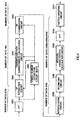
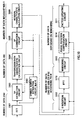
- FIG.10 is a block diagram with annotations made on the number of data pieces processed of various sections of the loop interference canceller 3a. Connections of various sections and their processing are completely the same as those in FIG.6 , and therefore explanations of the operation will be omitted.
- the number of data pieces corresponds to the case of mode 3 transmission according to the aforementioned ISDB-T scheme.
- the number of data pieces is 8192.
- the number of data pieces which is the number of SPs included in one symbol is 469.
- the input/output of the residual characteristic calculation circuit 3309 and the first input of the 0 insertion circuit 3312 the number of data pieces changes depending on the number of symbols M used for the rule R and it is (M*468+1) assuming that the pilot signal at the right end is included.
- the number of data pieces changes depending on the symbols used for the rule R, and it is 2048 with one symbol, 4096 with two symbols and 8192 with four symbols.
- the number of data pieces depends on the windowing processing. In reality, it may be 682 close to (8192/12) when the number of symbols used for the rule R is one and 1024 which corresponds to a typical guard time (1/8) symbol time when the number of symbols is 2 or 4.
- the number of data pieces handled is decreased drastically compared to the conventional example shown in FIG.4 and it can be expected to shorten the processing times of the respective sections and data input/output time among the respective sections.
- this embodiment can use only SP parts as the output of the transmission path characteristic estimation section, obtain a residual characteristic, then insert Os, apply IFFT and obtain a time domain signal corresponding to the residual characteristic of the entire band through windowing using a sampling theorem. Furthermore, unlike expansion to the incomplete entire band using a finite word length low pass filter of interpolation, expansion using the above described sampling theorem is expansion to the theoretically most accurate entire band.
- the loop interference canceller 3a by limiting the number of data pieces of the transmission path characteristic estimation section 331a and carrying out expansion to the entire band through 0 insertion in the frequency domain and windowing after the time domain conversion and speeding up the adaptive operation of the loop interference canceller by reducing the number of data pieces processed, it is possible to achieve advantages effects of realizing high trackability to time variations of the phase and level of loop interference wave or key station wave, performing processing inside more accurately, performing a high accuracy cancellation operation and realizing miniaturization of the apparatus with a reduced circuit scale.
- the present invention speeds up the adaptive operation of the loop interference canceller with a reduced number of data pieces processed, realizes high trackability with respect to time variations of the phase and level of loop interference wave or key station wave, performs processing inside with higher accuracy, performs a high accuracy cancellation operation, reduces the circuit scale, and can thereby achieve the advantageous effect of realizing miniaturization of the apparatus.
- This embodiment has described the loop interference canceller in an SFN relay system, but the present invention is also applicable to a repeater, etc., in a wireless LAN and mobile communication system if it is at least a system using an OFDM transmission scheme.
- the present invention relates to a loop interference canceller which cancels loop interference using a transmission path characteristic estimated from an OFDM (Orthogonal Frequency Division Multiplexing) signal and is applicable to a loop interference canceller, relay system and loop interference canceling system used, for example, for a relay broadcasting station and a repeater in a radio communication realizing broadcast wave relay SFN in terrestrial digital broadcasting.
- OFDM Orthogonal Frequency Division Multiplexing
Landscapes
- Engineering & Computer Science (AREA)
- Signal Processing (AREA)
- Computer Networks & Wireless Communication (AREA)
- Radio Relay Systems (AREA)
- Cable Transmission Systems, Equalization Of Radio And Reduction Of Echo (AREA)
Claims (10)
- Rückkopplungsentzerrer (3a) zum Entzerren einer Rückkopplung zwischen Sende-/Empfangsantennen (1, 5), wenn Mehrfachträgersignale, die über Bezugsträger (SP) in regelmäßigen Intervallen verfügen, auf derselben Frequenz für Senden und Empfangen zwischenverstärkt werden, enthaltend:einen Entzerrungsabschnitt (31), der dazu eingerichtet ist, eine Rückkopplung, die in einem empfangenen Signal enthalten ist, mit Hilfe eines Filters (32) zu entzerren, für das ein Faktor eingestellt ist;einen Sendewegcharakteristik-Schätzabschnitt (331 a), der dazu eingerichtet ist, die Sendewegcharakteristik eines Signals zu schätzen, nachdem die Rückkopplung entzerrt wurde;einen Restcharakteristik-Berechnungsabschnitt (3309) der dazu eingerichtet ist, einen Entzerrungsrest auf der Basis des Schätzergebnisses des Sendeweg-Schätzabschnittes (331 a) zu berechnen;einen Abschnitt (3310) für eine inverse schnelle Fouriertransformation undeinen Aktualisierungsabschnitt (3311), der dazu eingerichtet ist, den Faktor des Filters (32) zu aktualisieren;dadurch gekennzeichnet, dassder Rückkopplungsentzerrer (3a) weiterhin einen 0-Einfügeabschnitt (3312) enthält, der dazu eingerichtet ist, 0-Daten für die Ausgabe des Restcharakteristik-Berechnungsabschnittes (3309) einzufügen, undeinen Fensterbildungsabschnitt (3313), der im Bezug auf die Ausgabe aus dem Abschnitt (3310) der inversen, schnellen Fouriertransformation dazu eingerichtet ist, entweder einen Bereich ohne die sich wiederholende Komponente der Sendewegcharakteristik oder einen Bereich zu extrahieren, der durch den Faktor des Filters (32) festgelegt ist, welcher auch immer kleiner ist;wobei der Abschnitt (3310) für die inverse schnelle Fouriertransformation dazu eingerichtet ist, die Ausgabe aus dem 0-Einfügungsabschnitt in ein Zeitdomänensignal umzuwandeln undder Aktualisierungsabschnitt (3311) dazu eingerichtet ist, den Faktor des Filters (32) auf der Basis der Ausgabe aus dem Fensterbildungsabschnitt (3313) zu aktualisieren.
- Rückkopplungsentzerrer nach Anspruch 1, bei dem der Sendewegcharakteristik-Schätzabschnitt (331 a) enthält:einen Abschnitt (3301) für eine schnelle Fouriertransformation, der dazu eingerichtet ist, die Ausgabe aus dem Entzerrungsabschnitt (31), die ein Zeitdomänensignal ist, in ein Frequenzdomänensignal umzuwandeln;einen Bezugsträgerinformations-Extrahierabschnitt (3302), der dazu eingerichtet ist, Informationen, die eine Anordnung von Bezugsträgern (SP) kennzeichnen, und Signalkomponenten aus der Ausgabe des Abschnittes (3301) für die schnelle Fouriertransformation zu extrahieren;einen Bezugsträger-Extrahierabschnitt (3303), der dazu eingerichtet ist, lediglich Bezugsträger (SP) aus der Ausgabe des Abschnittes (3301) für die schnelle Fouriertransformation gemäß der Anordnung der Bezugsträger zu extrahieren, die man aus der Ausgabe des Bezugsträgerinformations-Extrahierabschnitts (3302) erhält; undeinen Sendewegcharakteristik-Berechnungsabschnitt (3304), der dazu eingerichtet ist, die Sendewegcharakteristik von Bezugsträgern (SP) zu berechnen, indem er die Ausgabe aus dem Abschnitt (3301) für die schnelle Fouriertransformation mit der Anordnung und der Signalkomponente der Bezugsträger (SP) vergleicht, die man aus der Ausgabe des Bezugsträgerinformations-Extrahierabschnitts (3302) erhält.
- Rückkopplungsentzerrer nach Anspruch 2, bei dem der Sendewegcharakteristik-Schätzabschnitt (331 a) dazu eingerichtet ist, die Sendewegcharakteristik lediglich unter Verwendung eines Satzes von Ausgaben aus dem Sendewegcharakteristik-Berechnungsabschnitt (3304) zu schätzen.
- Rückkopplungsentzerrer nach Anspruch 2, bei dem der Sendewegcharakteristik-Schätzabschnitt (331a) weiterhin einen Bezugsträger-Kombinationsabschnitt (33051) enthält, der dazu eingerichtet ist, eine Vielzahl von Sätzen von Ausgaben aus dem Sendewegcharakteristik-Berechnungsabschnitt (3304) zu speichern und die Sätze gespeicherter Ausgaben mit unterschiedlichen Anordnungen von Bezugsträgern (SP) gemäß der Anordnung von Bezugsträgern zu kombinieren, die man aus der Ausgabe des Bezugsträger-Extrahierabschnittes (3303) erhält,
wobei der Bezugsträger-Kombinierabschnitt (33051) dazu eingerichtet ist, lediglich zwei Sätze von Ausgaben zu kombinieren, in denen Bezugsträger (SP) in regelmäßigen Intervallen angeordnet sind, und
die Sendewegcharakteristik unter Verwendung der Ausgabe des Bezugsträger-Kombinierabschnittes (33051) geschätzt wird. - Rückkopplungsentzerrer nach Anspruch 2, bei dem der Sendewegcharakteristik-Schätzabschnitt (331a) weiterhin einen Bezugsträger-Kombinierabschnitt (33051) enthält, der dazu eingerichtet ist, eine Vielzahl von Sätzen von Ausgaben des Sendewegcharakteristik-Berechnungsabschnittes (3304) zu speichern und die Sätze gespeicherter Ausgaben mit unterschiedlichen Anordnungen von Bezugsträgern (SP) gemäß der Anordnung von Bezugsträgern zu kombinieren, die man aus der Ausgabe des Bezugsträger-Extrahierabschnittes (3303) erhält,
wobei der Bezugsträger-Kombinierabschnitt (33051) dazu eingerichtet ist, lediglich vier Sätze von Ausgaben zu kombinieren, in denen Bezugsträger (SP) in regelmäßigen Intervallen angeordnet sind, und
die Sendewegcharakteristik unter Verwendung der Ausgabe des Bezugsträger-Kombinierabschnittes (33051) geschätzt wird. - Rückkopplungsentzerrer nach Anspruch 1, bei dem ein spezieller Satz von Bezugsträgern, die keine Phasenrotationskompensationsverarbeitung benötigen, verwendet wird, wenn die Sendewegcharakteristik, die die Ausgabe des Sendewegcharakteristik-Schätzabschnittes (331 a) ist, geschätzt wird.
- Rückkopplungsentzerrer nach Anspruch 1, weiterhin enthaltend einen Phasenrotations-Kompensationsabschnitt (3314), der dazu eingerichtet ist, die Phasenrotationskompensation gemäß der Anordnung von Trägern auszuführen, die verwendet werden, um die Sendewegcharakteristik für die Ausgabe des Fensterbildungsabschnittes (3313) zu schätzen,
wobei der Aktualisierungsabschnitt (3311), dazu eingerichtet ist, einen Faktor des Filters (32) aus der Ausgabe des Phasenrotations-Kompensationsabschnittes (3314) zu erzeugen. - Rückkopplungsentzerrer nach Anspruch 4 oder 5, bei dem der Bezugsträger-Kombinierabschnitt (33051) dazu eingerichtet ist, die Anzahl von Sätzen von Ausgaben des Sendewegcharakteristik-Berechnungsabschnittes (3304) zu ändern, um sie zum Zeitpunkt des Startens oder Neustartens oder gemäß dem Zustand des Faktors des Filters (32) zu kombinieren.
- Zwischenverstärkungssystem mit einem Rückkopplungsentzerrer nach einem der Ansprüche 1 bis 8.
- Rückkopplungsentzerrverfahren zum Entzerren von Rückkopplungen zwischen Sende-/Empfangsantennen (1, 5), wenn Mehrfachträgersignale, die Bezugsträger (SP) in
regelmäßigen Intervallen haben, mit derselben Frequenz zum Senden und Empfangen zwischenverstärkt werden, umfassend:einen Entzerrschritt zum Entzerren einer Rückkopplung, die in einem Empfangssignal enthalten ist, unter Verwendung eines Filters (32), für das ein Faktor eingestellt ist;einen Sendewegcharakteristik-Schätzschritt zum Schätzen der Sendewegcharakteristik eines Signals, nachdem die Rückkopplung entzerrt wurde;einen Restcharakteristik-Berechnungsschritt zum Berechnen eines Entzerrungsrestes auf der Basis des Schätzergebnisses des Sendewegschätzschrittes;einen Schritt einer inversen schnellen Fouriertransformation undeinen Aktualisierungsschritt zum Aktualisieren des Faktors des Filters (32);dadurch gekennzeichnet, dassdas Rückkopplungsentzerrverfahren weiterhin einen 0-Einfügeschritt zum Einfügen von 0-Daten für das Ausgabeergebnis des Restcharakteristik-Berechnungsschrittes umfasst, unddurch einen Fensterbildungsschritt, um im Bezug auf die Ausgabe des Schrittes einer inversen schnellen Fouriertransformation entweder einen Bereich ohne der sich wiederholenden Komponente der Sendewegcharakteristik oder einen Bereich zu extrahieren, der durch den Faktor des Filters festgelegt ist, welcher auch immer kleiner ist,wobei der Schritt der inversen schnellen Fouriertransformation das Ausgabeergebnis des 0-Einfügeschrittes in ein Zeitdomänensignal umwandelt undder Aktualisierungsschritt den Faktor des Filters (32) auf der Basis des Ausgabeergebnisses des Fensterbildungsschrittes aktualisiert.
Applications Claiming Priority (5)
| Application Number | Priority Date | Filing Date | Title |
|---|---|---|---|
| JP2002299523 | 2002-10-11 | ||
| JP2002299523 | 2002-10-11 | ||
| JP2003343412A JP4464651B2 (ja) | 2002-10-11 | 2003-10-01 | 回り込みキャンセラ、中継システム及び回り込みキャンセル方法 |
| JP2003343412 | 2003-10-01 | ||
| PCT/JP2003/012751 WO2004034607A1 (ja) | 2002-10-11 | 2003-10-06 | 回り込みキャンセラ、中継システム及び 回り込みキャンセル方法 |
Publications (3)
| Publication Number | Publication Date |
|---|---|
| EP1545022A1 EP1545022A1 (de) | 2005-06-22 |
| EP1545022A4 EP1545022A4 (de) | 2011-05-04 |
| EP1545022B1 true EP1545022B1 (de) | 2012-01-11 |
Family
ID=32095444
Family Applications (1)
| Application Number | Title | Priority Date | Filing Date |
|---|---|---|---|
| EP03748705A Expired - Lifetime EP1545022B1 (de) | 2002-10-11 | 2003-10-06 | Rückkopplungsentzerrer, zwischenverstärker und verfahren zur rückkopplungsentzerrung |
Country Status (5)
| Country | Link |
|---|---|
| US (1) | US7406140B2 (de) |
| EP (1) | EP1545022B1 (de) |
| JP (1) | JP4464651B2 (de) |
| AU (1) | AU2003268759A1 (de) |
| WO (1) | WO2004034607A1 (de) |
Families Citing this family (22)
| Publication number | Priority date | Publication date | Assignee | Title |
|---|---|---|---|---|
| JP4652846B2 (ja) * | 2004-03-11 | 2011-03-16 | パナソニック株式会社 | 通信端末装置および通信中継方法 |
| US20050230354A1 (en) * | 2004-04-14 | 2005-10-20 | Hardikar Vishwas V | Method and composition of post-CMP wetting of thin films |
| WO2006115320A1 (en) * | 2005-04-25 | 2006-11-02 | Electronics And Telecommunications Research Institute | Apparatus and method of on-channel repeater |
| US8619884B2 (en) * | 2005-09-02 | 2013-12-31 | Qualcomm Incorporated | Communication channel estimation |
| JP4745072B2 (ja) * | 2006-02-02 | 2011-08-10 | 日本無線株式会社 | 受信装置 |
| JP4704229B2 (ja) * | 2006-02-02 | 2011-06-15 | 日本無線株式会社 | 受信装置 |
| US7715785B2 (en) * | 2006-04-21 | 2010-05-11 | Powerwave Technologies, Inc. | System and method for estimation and compensation of radiated feedback coupling in a high gain repeater |
| KR100873487B1 (ko) * | 2007-05-09 | 2008-12-15 | 한국전자통신연구원 | 동일채널 중계장치 및 그 방법 |
| KR100830695B1 (ko) * | 2007-06-22 | 2008-05-20 | 에스케이텔레시스 주식회사 | 디지털 적응 간섭제거 중계기 |
| KR100877486B1 (ko) | 2007-06-22 | 2009-01-08 | 에스케이텔레시스 주식회사 | 디지털 적응 간섭제거 중계기 |
| KR101002839B1 (ko) * | 2007-07-31 | 2010-12-21 | 삼성전자주식회사 | 통신 시스템에서 간섭 제거를 위한 중계국 장치 및 방법 |
| US20100075595A1 (en) * | 2008-04-17 | 2010-03-25 | Cellynx, Inc. | Dual Loop Active and Passive Repeater Antenna Isolation Improvement |
| ITMO20080161A1 (it) | 2008-05-27 | 2009-11-28 | Meta System Spa | Dispositivo ripetitore perfezionato per la cancellazione e/o riduzione di segnali di eco e relativo metodo |
| JP5068230B2 (ja) * | 2008-08-22 | 2012-11-07 | 日本放送協会 | Ofdmデジタル信号等化装置、等化方法及び中継装置 |
| US9049065B2 (en) * | 2009-05-11 | 2015-06-02 | Qualcomm Incorporated | Removal of ICI/ISI errors in frequency domain channel estimation for wireless repeaters |
| US8385818B2 (en) * | 2009-05-11 | 2013-02-26 | Qualcomm Incorporated | Delay control to improve frequency domain channel estimation in an echo cancellation repeater |
| US8611227B2 (en) * | 2009-05-11 | 2013-12-17 | Qualcomm Incorporated | Channel estimate pruning in presence of large signal dynamics in an interference cancellation repeater |
| US20110116531A1 (en) * | 2009-05-11 | 2011-05-19 | Qualcomm Incorporated | Removal of multiplicative errors in frequency domain channel estimation for wireless repeaters |
| WO2011102762A1 (en) * | 2010-02-17 | 2011-08-25 | Saab Ab | Wideband transmitter/receiver arrangement for multifunctional radar and communication |
| US9621391B2 (en) * | 2013-09-24 | 2017-04-11 | Huawei Technologies Co., Ltd. | Methods and apparatuses to improve reception of direct detection optical signals |
| KR102129063B1 (ko) * | 2015-12-31 | 2020-07-01 | 주식회사 쏠리드 | 중계기 및 이의 신호 감쇄 방법 |
| US10014914B1 (en) * | 2017-06-13 | 2018-07-03 | Hughes Network Systems, L.L.C. | Adaptive interference canceller for multiple reference inputs |
Family Cites Families (8)
| Publication number | Priority date | Publication date | Assignee | Title |
|---|---|---|---|---|
| KR100224863B1 (ko) | 1997-08-20 | 1999-10-15 | 윤종용 | Ofdm 수신기를 위한 등화 방법과 등화기 |
| JP4409639B2 (ja) | 1998-06-10 | 2010-02-03 | 日本放送協会 | 回り込みキャンセラ |
| EP1014609B1 (de) * | 1998-07-13 | 2004-09-22 | Sony Corporation | Mehrträgerkommunikationsverfahren, sender und empfänger |
| JP4040228B2 (ja) | 2000-02-07 | 2008-01-30 | 松下電器産業株式会社 | 回り込みキャンセラ |
| US20020048333A1 (en) * | 2000-05-25 | 2002-04-25 | Nadeem Ahmed | Joint detection in OFDM systems |
| SG99310A1 (en) * | 2000-06-16 | 2003-10-27 | Oki Techno Ct Singapore Pte | Methods and apparatus for reducing signal degradation |
| WO2002067526A2 (en) * | 2001-02-22 | 2002-08-29 | Koninklijke Philips Electronics N.V. | Channel estimation in multicarrier transmission systems |
| EP1422850A4 (de) * | 2001-08-28 | 2006-04-05 | Matsushita Electric Industrial Co Ltd | Störungsentfernungsvorrichtung und verfahren mit mehreren durchgängen |
-
2003
- 2003-10-01 JP JP2003343412A patent/JP4464651B2/ja not_active Expired - Fee Related
- 2003-10-06 US US10/526,476 patent/US7406140B2/en not_active Expired - Lifetime
- 2003-10-06 EP EP03748705A patent/EP1545022B1/de not_active Expired - Lifetime
- 2003-10-06 WO PCT/JP2003/012751 patent/WO2004034607A1/ja not_active Ceased
- 2003-10-06 AU AU2003268759A patent/AU2003268759A1/en not_active Abandoned
Also Published As
| Publication number | Publication date |
|---|---|
| JP4464651B2 (ja) | 2010-05-19 |
| EP1545022A4 (de) | 2011-05-04 |
| US20050191961A1 (en) | 2005-09-01 |
| WO2004034607A1 (ja) | 2004-04-22 |
| JP2004153799A (ja) | 2004-05-27 |
| AU2003268759A1 (en) | 2004-05-04 |
| US7406140B2 (en) | 2008-07-29 |
| EP1545022A1 (de) | 2005-06-22 |
Similar Documents
| Publication | Publication Date | Title |
|---|---|---|
| EP1545022B1 (de) | Rückkopplungsentzerrer, zwischenverstärker und verfahren zur rückkopplungsentzerrung | |
| KR100355326B1 (ko) | Ofdm 통신 장치 및 전파로 추정 방법 | |
| KR20010071441A (ko) | 간섭에 의한 방해파 캔슬러 | |
| US9608713B2 (en) | Apparatus and method for removing interference by ICS repeater using standardizer | |
| WO2009061084A1 (en) | Interference cancellation apparatus and method in wibro repeater | |
| US6542560B1 (en) | Method of channel estimation and compensation based thereon | |
| JP3842680B2 (ja) | 回り込みキャンセラおよび多段中継方式 | |
| JP2003110528A (ja) | Ofdm用周波数特性検出器、ofdm用周波数特性補償器及びofdm用中継装置 | |
| CN100442681C (zh) | 环路干扰消除器、中继系统和环路干扰消除方法 | |
| JP4040228B2 (ja) | 回り込みキャンセラ | |
| JP4109530B2 (ja) | 回り込みキャンセラ | |
| JP4362246B2 (ja) | ダイバーシティ受信用回り込みキャンセル装置及び中継システム | |
| KR100976726B1 (ko) | 동일채널 중계장치 및 그 방법 | |
| JP3787040B2 (ja) | 回り込みキャンセラ | |
| KR101058734B1 (ko) | 통신 시스템의 신호 송수신 장치에서 반향 신호 제거 장치 및 방법 | |
| JP6231305B2 (ja) | 回り込み伝送路推定装置及び回り込みキャンセラ | |
| JP6110650B2 (ja) | 回り込みキャンセラおよび中継装置 | |
| JP4420797B2 (ja) | 干渉キャンセラ及び当該干渉キャンセラを用いる中継装置 | |
| US7715486B2 (en) | Method and device for estimating the transfer function of the transmission channel for a COFDM demodulator | |
| KR100695005B1 (ko) | 직교주파수분할다중 기반 수신기의 채널 추정 장치 및 그방법 | |
| US7801229B2 (en) | Method and device for estimating the transfer function of the transmission channel for a COFDM demodulator | |
| US8446814B2 (en) | Radio communication system, radio communication device, radio communication method, and program | |
| JP4569591B2 (ja) | Ofdm系sfn中継装置における回り込み波の適応キャンセリング方法 | |
| JP2002300094A (ja) | 放送中継局装置及び回り込みキャンセル方法 | |
| JP5049730B2 (ja) | 中継装置 |
Legal Events
| Date | Code | Title | Description |
|---|---|---|---|
| PUAI | Public reference made under article 153(3) epc to a published international application that has entered the european phase |
Free format text: ORIGINAL CODE: 0009012 |
|
| 17P | Request for examination filed |
Effective date: 20050407 |
|
| AK | Designated contracting states |
Kind code of ref document: A1 Designated state(s): AT BE BG CH CY CZ DE DK EE ES FI FR GB GR HU IE IT LI LU MC NL PT RO SE SI SK TR |
|
| AX | Request for extension of the european patent |
Extension state: AL LT LV MK |
|
| DAX | Request for extension of the european patent (deleted) | ||
| RBV | Designated contracting states (corrected) |
Designated state(s): DE FR GB |
|
| RAP1 | Party data changed (applicant data changed or rights of an application transferred) |
Owner name: PANASONIC CORPORATION |
|
| A4 | Supplementary search report drawn up and despatched |
Effective date: 20110405 |
|
| RIC1 | Information provided on ipc code assigned before grant |
Ipc: H04B 7/015 20060101AFI20040426BHEP Ipc: H04B 7/155 20060101ALI20110330BHEP Ipc: H04J 11/00 20060101ALI20110330BHEP |
|
| 17Q | First examination report despatched |
Effective date: 20110428 |
|
| GRAP | Despatch of communication of intention to grant a patent |
Free format text: ORIGINAL CODE: EPIDOSNIGR1 |
|
| RIC1 | Information provided on ipc code assigned before grant |
Ipc: H04B 7/155 20060101ALI20110720BHEP Ipc: H04J 11/00 20060101ALI20110720BHEP Ipc: H04B 7/015 20060101AFI20110720BHEP |
|
| GRAS | Grant fee paid |
Free format text: ORIGINAL CODE: EPIDOSNIGR3 |
|
| GRAA | (expected) grant |
Free format text: ORIGINAL CODE: 0009210 |
|
| AK | Designated contracting states |
Kind code of ref document: B1 Designated state(s): DE FR GB |
|
| REG | Reference to a national code |
Ref country code: GB Ref legal event code: FG4D |
|
| REG | Reference to a national code |
Ref country code: DE Ref legal event code: R096 Ref document number: 60339684 Country of ref document: DE Effective date: 20120315 |
|
| PLBE | No opposition filed within time limit |
Free format text: ORIGINAL CODE: 0009261 |
|
| STAA | Information on the status of an ep patent application or granted ep patent |
Free format text: STATUS: NO OPPOSITION FILED WITHIN TIME LIMIT |
|
| 26N | No opposition filed |
Effective date: 20121012 |
|
| REG | Reference to a national code |
Ref country code: DE Ref legal event code: R097 Ref document number: 60339684 Country of ref document: DE Effective date: 20121012 |
|
| REG | Reference to a national code |
Ref country code: FR Ref legal event code: PLFP Year of fee payment: 13 |
|
| REG | Reference to a national code |
Ref country code: FR Ref legal event code: PLFP Year of fee payment: 14 |
|
| REG | Reference to a national code |
Ref country code: FR Ref legal event code: PLFP Year of fee payment: 15 |
|
| REG | Reference to a national code |
Ref country code: FR Ref legal event code: PLFP Year of fee payment: 16 |
|
| PGFP | Annual fee paid to national office [announced via postgrant information from national office to epo] |
Ref country code: GB Payment date: 20211022 Year of fee payment: 19 Ref country code: DE Payment date: 20211020 Year of fee payment: 19 |
|
| PGFP | Annual fee paid to national office [announced via postgrant information from national office to epo] |
Ref country code: FR Payment date: 20221028 Year of fee payment: 20 |
|
| REG | Reference to a national code |
Ref country code: DE Ref legal event code: R119 Ref document number: 60339684 Country of ref document: DE |
|
| GBPC | Gb: european patent ceased through non-payment of renewal fee |
Effective date: 20221006 |
|
| PG25 | Lapsed in a contracting state [announced via postgrant information from national office to epo] |
Ref country code: DE Free format text: LAPSE BECAUSE OF NON-PAYMENT OF DUE FEES Effective date: 20230503 |
|
| PG25 | Lapsed in a contracting state [announced via postgrant information from national office to epo] |
Ref country code: GB Free format text: LAPSE BECAUSE OF NON-PAYMENT OF DUE FEES Effective date: 20221006 |