EP1544953A1 - Federverbinder - Google Patents
Federverbinder Download PDFInfo
- Publication number
- EP1544953A1 EP1544953A1 EP04029608A EP04029608A EP1544953A1 EP 1544953 A1 EP1544953 A1 EP 1544953A1 EP 04029608 A EP04029608 A EP 04029608A EP 04029608 A EP04029608 A EP 04029608A EP 1544953 A1 EP1544953 A1 EP 1544953A1
- Authority
- EP
- European Patent Office
- Prior art keywords
- terminal
- pin
- conductive pin
- contact
- casing
- Prior art date
- Legal status (The legal status is an assumption and is not a legal conclusion. Google has not performed a legal analysis and makes no representation as to the accuracy of the status listed.)
- Withdrawn
Links
- 230000003252 repetitive effect Effects 0.000 description 3
- 239000004020 conductor Substances 0.000 description 2
- 239000002184 metal Substances 0.000 description 2
- 229910052751 metal Inorganic materials 0.000 description 2
- 239000011347 resin Substances 0.000 description 2
- 229920005989 resin Polymers 0.000 description 2
- 230000000903 blocking effect Effects 0.000 description 1
- PCHJSUWPFVWCPO-UHFFFAOYSA-N gold Chemical compound [Au] PCHJSUWPFVWCPO-UHFFFAOYSA-N 0.000 description 1
- 239000010931 gold Substances 0.000 description 1
- 229910052737 gold Inorganic materials 0.000 description 1
- 238000004519 manufacturing process Methods 0.000 description 1
- 238000000465 moulding Methods 0.000 description 1
- 238000005476 soldering Methods 0.000 description 1
Images


Classifications
-
- H—ELECTRICITY
- H01—ELECTRIC ELEMENTS
- H01R—ELECTRICALLY-CONDUCTIVE CONNECTIONS; STRUCTURAL ASSOCIATIONS OF A PLURALITY OF MUTUALLY-INSULATED ELECTRICAL CONNECTING ELEMENTS; COUPLING DEVICES; CURRENT COLLECTORS
- H01R13/00—Details of coupling devices of the kinds covered by groups H01R12/70 or H01R24/00 - H01R33/00
- H01R13/02—Contact members
- H01R13/22—Contacts for co-operating by abutting
- H01R13/24—Contacts for co-operating by abutting resilient; resiliently-mounted
- H01R13/2407—Contacts for co-operating by abutting resilient; resiliently-mounted characterized by the resilient means
- H01R13/2421—Contacts for co-operating by abutting resilient; resiliently-mounted characterized by the resilient means using coil springs
-
- H—ELECTRICITY
- H01—ELECTRIC ELEMENTS
- H01R—ELECTRICALLY-CONDUCTIVE CONNECTIONS; STRUCTURAL ASSOCIATIONS OF A PLURALITY OF MUTUALLY-INSULATED ELECTRICAL CONNECTING ELEMENTS; COUPLING DEVICES; CURRENT COLLECTORS
- H01R13/00—Details of coupling devices of the kinds covered by groups H01R12/70 or H01R24/00 - H01R33/00
- H01R13/02—Contact members
- H01R13/15—Pins, blades or sockets having separate spring member for producing or increasing contact pressure
- H01R13/187—Pins, blades or sockets having separate spring member for producing or increasing contact pressure with spring member in the socket
Definitions
- the present invention relates to a spring connector which has high reliability and can be manufactured at low cost.
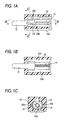
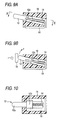
- Figs. 9A to 11 C show a conventional spring connector disclosed in Japanese Patent Publication No. 2003-17173A.
- the conventional spring connector comprises a plate-shaped terminal 10 made of conductive material, a conductive pin 12 which can slide with respect to the terminal 10, a coil spring 14 which is provided between the terminal 10 and the conductive pin 12 in a compressed state, and a holder 16 formed of insulating resin.
- the terminal 10 is formed of an elongated sheet metal which has been folded to form a substantially U-shape as shown in Fig. 11 C.
- a dented part 10a which opens in a forward direction is formed in one of the folded halves of the terminal 10, and a small protrusion 10b is formed at a center of a bottom edge of the dented part 10a, as shown in Figs. 11 A and 11 B.
- the other of the folded halves serves as a connecting part 10c to be fixed by soldering or so to a circuit board (not shown).
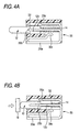
- the conductive pin 12 has a plunger part 12a having a relatively small diameter at its tip end side and a protruded part 12b having a relatively large diameter at its base end side.
- This protruded part 12b is provided with axially extending grooves 12c on both sides thereof. These grooves 12c are adapted to be engaged with opposed inner edges of the dented part 10a in the terminal 10, and the conductive pin 12 is arranged so as to slide with respect to the terminal 10 along the grooves 12c, as guides for the sliding movement.
- the conductive pin 12 is further provided with a blind hole 12d in an axial direction form its base end face.
- the terminal 10 and the conductive pin 12 may be plated with gold as required.
- the conductive pin 12 is slidably incorporated into the holder 16 such that a tip end of the plunger part 12a is projected from the holder 16 so as not to be pulled out.
- the terminal 10 appropriately fixed to the conductive pin 12 is also incorporated into the holder 16.
- the conductive pin 12 is so designed as to be slidable in an axial direction thereof and in a diagonal direction with respect to a bottom face of the holder 16.
- the coil spring 14 is provided in a compressed state between the conductive pin 12 and the bottom edge of the dented part 10a in the terminal 10, having its one end inserted into the blind hole 12d in the conductive pin 12 and the other end blocked by the protrusion 10b at the center of the bottom edge of the dented part 10a in the terminal 10 so as not to be displaced.
- the connecting part 10c of the terminal 10 is disposed on the bottom face of the holder 16.
- the conductive pin 12 In order to reliably obtain the electrical connection between the conductive pin 12 and the terminal 10, it is necessary for the conductive pin 12 to be pushed into the holder 16 in a direction inclined at a certain angle with respect to the bottom face of the holder, but not in parallel with the bottom face. In other words, the direction of pushing in the conductive pin 12 is so set as to be inclined at a certain angle with respect to a direction of movement of the contact terminal 18. Consequently, a height of the conductive pin 12 from the bottom face is increased by the amount of the inclination.
- a spring connector comprising:
- the elastic piece is always brought into contact with the conductive pin, the electrical connection between the pin and the terminal can be reliably established even if the sliding direction of the pin is made parallel with the bottom face of the casing. Accordingly, the height dimension of the spring connector can be reduced.
- a pair of grooves are formed on both side portions of the pin so as to extend in the first direction.
- a pair of guide members are formed on one of the terminal and the casing so as to be fitted into the grooves, respectively. Each of the guide members comes in slide contact with an inner face of each of the grooves when the elastic piece is brought into contact with the pin.
- the guide members are provided as a part of the casing, since the guide members are monolithically molded with the casing made of resin or the like, the weight of the spring connector can be reduced. Furthermore, the shape of the terminal can be simplified.
- two elastic pieces are brought into contact with the pin from opposite sides.
- the elastic pieces are brought into contact with different positions in the first direction.
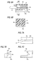
- the conductive pin 12 as shown in Figs. 3A to 3C which is the same as the one employed in the above described conventional example, has a plunger part 12a, a protruded part 12b, grooves 12c, and a blind hole 12d.
- a plate-shaped terminal 20 formed of conductive material is made of an elongated sheet metal which has been folded into halves in a substantially U-shape, as shown in Fig. 2C.
- One of the folded halves is divided lengthwise into three parts, namely, a center part and both side parts as shown in Figs. 2A and 2B.
- the both side parts are formed substantially in parallel with the other of the folded halves which serves as a connecting part 20a, and inside edges of the both side parts are opposed in parallel with each other to form guide parts 20b.
- the center part is formed as an elastic contact part 20c which is adapted to be brought into elastic contact with the conductive pin 12 from above.
- the elastic contact part 20c is brought into elastic contact with the conductive pin 12 within a sliding range of the conductive pin 12.
- the terminal 20 is provided with a protrusion 20d for blocking the coil spring 14 from being displaced at its base end side. Then, the coil spring 14 is disposed in a compressed state between the conductive pin 12 and the terminal 20 having its one end inserted into the blind hole 12d in the conductive pin 12 and the other end blocked by the protrusion 20d of the terminal 20 from being displaced, and in this state, the conductive pin 12 is assembled to the terminal 20.
- an assembled unit of the conductive pin 12, the terminal 20, and the coil spring 14 is incorporated into a holder 22 appropriately, so that the terminal 20 may not be pulled out.
- a tip end of the plunger part 12a of the conductive pin 12 is projected from the holder 22, and the conductive pin 12 is restricted from being pulled out in a projecting direction by the presence of the protruded part 12b.
- the connecting part 20a of the terminal 20 is disposed on the bottom face of the holder 22.
- the elastic contact part 20c of the terminal 20 is always in contact with the conductive pin 12, it is unnecessary to incline the sliding direction in the conductive pin 12 at a certain angle with respect to the direction of movement of the contact terminal 18, as in the conventional example. Even though the directions are in parallel with each other, reliable electrical connection can be obtained.
- the grooves 12c in the conductive pin 12 are pressed against upper faces of the guide parts 20b with an elastic force of the elastic contact part 20c, and electrical connection can be obtained also in these areas.
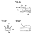
- the second embodiment is different from the first embodiment in that, in addition'to the elastic contact part 20c adapted to be brought into elastic contact with the conductive pin 12 from the above, a plate-shaped terminal 30 is provided with another elastic part 30c which is adapted to be brought into elastic contact with the conductive pin 12 from below, as shown in Figs. 5A to 5C. It is apparent that this elastic contact part 30c is formed in a holder 32 in such a manner that the elastic contact part 30c can be contacted with the conductive pin 12 from the below. Moreover, in the second embodiment, the elastic contact part 30c is so formed as to be brought into elastic contact with the conductive pin 12, at the almost final stage of the pushing operation of the conductive pin 12, as shown in Fig. 4B.
- the two elastic contact parts 20c and 30c are brought into elastic contact with the conductive pin 12, and reliable electrical connection can be obtained. Moreover, because positions where the two elastic contact parts 20c, 30c are brought into elastic contact with the conductive pin 12 are different in the sliding direction, a prying force is exerted on the conductive pin 12, and the guide parts 20b of the terminal 30 are strongly pressed against both end parts of the grooves 12c in the conductive pin 12 to attain reliable electrical connection also in these areas. In order to pry the conductive pin 12 by these two elastic contact parts 20c, 30c, it is necessary to provide a play for the sliding movement of the conductive pin 12.
- the additional elastic contact part 30c comes in contact with the conductive pin 12 at the almost final stage of the pushing operation of the conductive pin 12, there may be configured such that the completion of the contact operation of the contact terminal 18 is recognized through the use of the elastic contact part 30c.
- the two elastic contact parts 20c, 30c may be brought into elastic contact with the conductive pin 12 in relatively opposed positions.
- the third embodiment is different from the second embodiment in that, unlike the plate-shaped terminal 30 in the second embodiment, a plate-shaped terminal 40 is not provided with a pair of guide parts 20b. Instead of the guide parts 20b, a holder 42 is provided with a pair of guide parts 42a which are adapted to be engaged with the grooves 12c in the conductive pin 12 thereby allowing the conductive pin 12 to slide.
- a shape of the terminal 40 is more simplified.
- the holder side guide parts 42a can be easily formed by molding them integrally with the holder 42, and the entire spring connector can be advantageously manufactured with light weight and at low cost.
- FIG. 8A to 8C Components similar to those in the above embodiments will be designated by the same reference numerals, and repetitive explanations for those will be omitted.
- a plate-shaped terminal 50 is folded into a U-shape in a sectional view perpendicular to the sliding direction of the conductive pin 12, thus forming a pair of side parts extended inward from both sides of the connecting part 20a. Inner edges of the side parts serve as guide parts 50b.
- a holder is not shown in the drawing, it is apparent that the holder is formed in such a manner that the terminal 50 can be appropriately arranged and fixed thereon.
- the fourth embodiment having the above described structure is more suitably employed for manufacturing the spring connector provided with the guide parts 50b which have strong mechanical strength, as compared with the first embodiment.
- the conductive pin 12 is guided in the sliding direction, by engagement of the guide parts 20b of the terminals 20, 30, 40 and the holder side guide parts 42a with the grooves 12c in the protruded part 12b.
- the holder may be appropriately provided with a hole through which the plunger part 12a and the protruded part 12b of the conductive pin 12 are slidable. Any structure can be employed under a condition that the conductive pin 12 can be retractably projected, and the elastic contact part of the terminal can be brought into elastic contact to attain the electrical connection.
Landscapes
- Coupling Device And Connection With Printed Circuit (AREA)
Applications Claiming Priority (2)
| Application Number | Priority Date | Filing Date | Title |
|---|---|---|---|
| JP2003417930A JP4224389B2 (ja) | 2003-12-16 | 2003-12-16 | スプリングコネクタ |
| JP2003417930 | 2003-12-16 |
Publications (1)
| Publication Number | Publication Date |
|---|---|
| EP1544953A1 true EP1544953A1 (de) | 2005-06-22 |
Family
ID=34510616
Family Applications (1)
| Application Number | Title | Priority Date | Filing Date |
|---|---|---|---|
| EP04029608A Withdrawn EP1544953A1 (de) | 2003-12-16 | 2004-12-14 | Federverbinder |
Country Status (4)
| Country | Link |
|---|---|
| US (1) | US7094112B2 (de) |
| EP (1) | EP1544953A1 (de) |
| JP (1) | JP4224389B2 (de) |
| CN (1) | CN1630139A (de) |
Cited By (1)
| Publication number | Priority date | Publication date | Assignee | Title |
|---|---|---|---|---|
| EP3671968A3 (de) * | 2018-12-21 | 2020-09-23 | Tyco Electronics (Shanghai) Co., Ltd. | Elektrisches verbindergehäuse, elektrischer verbinder und elektrische verbinderanordnung |
Families Citing this family (28)
| Publication number | Priority date | Publication date | Assignee | Title |
|---|---|---|---|---|
| FI116920B (fi) * | 2003-12-10 | 2006-03-31 | Yokowo Seisakusho Kk | Liitin |
| DE102005012930A1 (de) * | 2005-03-15 | 2006-09-21 | Siemens Ag | Elektrische Kontaktanordnung mit einem ersten und einem zweiten Kontaktstück |
| JP2008045507A (ja) * | 2006-08-18 | 2008-02-28 | Nikki Co Ltd | 電磁燃料ポンプ |
| JP2008045508A (ja) * | 2006-08-18 | 2008-02-28 | Nikki Co Ltd | 電磁燃料ポンプ |
| JP2009026585A (ja) * | 2007-07-19 | 2009-02-05 | Yokowo Co Ltd | ライトアングルタイプのスプリングコネクタ |
| US8512079B2 (en) * | 2009-09-17 | 2013-08-20 | Henge Docks Llc | Docking station for an electronic device with improved electrical interface |
| US9285831B2 (en) | 2009-09-17 | 2016-03-15 | Henge Docks Llc | Docking station for portable electronics |
| JP2011096606A (ja) * | 2009-11-02 | 2011-05-12 | Smk Corp | ポゴピン式圧接型コネクタ |
| US8628358B2 (en) * | 2010-04-16 | 2014-01-14 | Hon Hai Precision Industry Co., Ltd. | Electrical connector having movable central contact |
| FR2971892A1 (fr) | 2011-02-22 | 2012-08-24 | Souriau | Contact electrique et ensemble connecteur a fort nombre de manoeuvres |
| JP5316821B2 (ja) * | 2011-05-11 | 2013-10-16 | Smk株式会社 | 圧接型コネクタ |
| JP5131611B2 (ja) * | 2011-08-31 | 2013-01-30 | Smk株式会社 | ポゴピン式圧接型コネクタ |
| US9650814B2 (en) | 2013-12-31 | 2017-05-16 | Henge Docks Llc | Alignment and drive system for motorized horizontal docking station |
| US9927838B2 (en) | 2013-12-31 | 2018-03-27 | Henge Docks Llc | Sensor system for docking station |
| US10018514B2 (en) * | 2014-02-17 | 2018-07-10 | Haier Us Appliance Solutions, Inc. | Cooktop temperature sensors and methods of operation |
| CN105006674A (zh) * | 2014-04-23 | 2015-10-28 | 贝尔威勒电子股份有限公司 | 具有伸缩端子的连接器结构改良 |
| TWI589065B (zh) * | 2014-11-10 | 2017-06-21 | 貝爾威勒電子股份有限公司 | 具伸縮端子之連接器結構 |
| US9887478B2 (en) * | 2015-04-21 | 2018-02-06 | Varian Semiconductor Equipment Associates, Inc. | Thermally insulating electrical contact probe |
| US9811118B2 (en) | 2015-10-23 | 2017-11-07 | Henge Docks Llc | Secure assembly for a docking station |
| US9575510B1 (en) | 2015-10-23 | 2017-02-21 | Matthew Leigh Vroom | Precision docking station for an electronic device having integrated retention mechanism |
| US9727084B2 (en) | 2015-10-23 | 2017-08-08 | Henge Docks Llc | Drivetrain for a motorized docking station |
| CN205319469U (zh) * | 2015-12-16 | 2016-06-15 | 华为技术有限公司 | 射频连接器 |
| JP2018009790A (ja) * | 2016-07-11 | 2018-01-18 | アルプス電気株式会社 | スプリングコンタクトおよびスプリングコンタクトを使用したソケット |
| JP2018009789A (ja) * | 2016-07-11 | 2018-01-18 | アルプス電気株式会社 | スプリングコンタクトと、スプリングコンタクトを使用したソケット、およびスプリングコンタクトの製造方法 |
| US9647367B1 (en) * | 2016-09-30 | 2017-05-09 | General Electric Company | Current restrictive spring-loaded electrical connection device |
| US9882301B1 (en) * | 2016-09-30 | 2018-01-30 | General Electric Company | Current restrictive spring-loaded electrical connection device |
| US10365688B1 (en) | 2018-04-19 | 2019-07-30 | Henge Docks Llc | Alignment sleeve for docking station |
| CN112993696B (zh) * | 2021-02-24 | 2023-08-22 | 安徽新城电力工程建设有限公司 | 一种智能电网用汇流箱 |
Citations (2)
| Publication number | Priority date | Publication date | Assignee | Title |
|---|---|---|---|---|
| US5681187A (en) * | 1995-08-29 | 1997-10-28 | Yazaki Corporation | Connector with movable contact member and resilient contact band |
| EP1253674A2 (de) * | 2001-04-27 | 2002-10-30 | Yokowo Co., Ltd. | Federsteckverbinder |
Family Cites Families (2)
| Publication number | Priority date | Publication date | Assignee | Title |
|---|---|---|---|---|
| US4904213A (en) * | 1989-04-06 | 1990-02-27 | Motorola, Inc. | Low impedance electric connector |
| JP2005050738A (ja) * | 2003-07-31 | 2005-02-24 | Jst Mfg Co Ltd | 電気コネクタ |
-
2003
- 2003-12-16 JP JP2003417930A patent/JP4224389B2/ja not_active Expired - Fee Related
-
2004
- 2004-12-14 EP EP04029608A patent/EP1544953A1/de not_active Withdrawn
- 2004-12-15 CN CN200410102051.1A patent/CN1630139A/zh active Pending
- 2004-12-15 US US11/011,157 patent/US7094112B2/en not_active Expired - Fee Related
Patent Citations (2)
| Publication number | Priority date | Publication date | Assignee | Title |
|---|---|---|---|---|
| US5681187A (en) * | 1995-08-29 | 1997-10-28 | Yazaki Corporation | Connector with movable contact member and resilient contact band |
| EP1253674A2 (de) * | 2001-04-27 | 2002-10-30 | Yokowo Co., Ltd. | Federsteckverbinder |
Cited By (1)
| Publication number | Priority date | Publication date | Assignee | Title |
|---|---|---|---|---|
| EP3671968A3 (de) * | 2018-12-21 | 2020-09-23 | Tyco Electronics (Shanghai) Co., Ltd. | Elektrisches verbindergehäuse, elektrischer verbinder und elektrische verbinderanordnung |
Also Published As
| Publication number | Publication date |
|---|---|
| CN1630139A (zh) | 2005-06-22 |
| US7094112B2 (en) | 2006-08-22 |
| JP2005183025A (ja) | 2005-07-07 |
| US20050130507A1 (en) | 2005-06-16 |
| JP4224389B2 (ja) | 2009-02-12 |
Similar Documents
| Publication | Publication Date | Title |
|---|---|---|
| US7094112B2 (en) | Spring connector having elastic terminal | |
| US6783405B1 (en) | Terminal for electric connector for communication apparatus | |
| US7404731B2 (en) | Electrical connector | |
| US9466907B2 (en) | Connector | |
| US6626708B2 (en) | Single piece spring contact | |
| US7256593B2 (en) | Electrical contact probe with compliant internal interconnect | |
| US8197272B2 (en) | Connector | |
| US7278861B2 (en) | Connector assembly | |
| US6572392B2 (en) | Push-push type card connector comprising a cam mechanism using a generally heart-shaped cam groove | |
| US6855010B1 (en) | Terminal for electric connector for communication apparatus | |
| KR20040073256A (ko) | 가압식 스프링 커넥터 | |
| US6241541B1 (en) | Switch-equipped coaxial connector | |
| CN109004411B (zh) | 多触点连接器 | |
| GB2342237A (en) | Jack | |
| EP0944135B1 (de) | Klemmenanordnung eines Steckverbinders | |
| US7144278B2 (en) | Plug connector equipped with compression contact terminals | |
| US6929491B1 (en) | Card connector | |
| US6361338B1 (en) | Electrical card connector | |
| US7131853B2 (en) | Card connector | |
| US6382994B1 (en) | Electrical connector having an ejector for withdrawing an inserted electronic card | |
| US20010000499A1 (en) | Switch-equipped coaxial connector | |
| US6354856B1 (en) | IC socket and contact pin thereof | |
| US6191373B1 (en) | Dial programming switch | |
| US8096821B2 (en) | Electrical card connector | |
| US10637191B2 (en) | Connector and connector assembly |
Legal Events
| Date | Code | Title | Description |
|---|---|---|---|
| PUAI | Public reference made under article 153(3) epc to a published international application that has entered the european phase |
Free format text: ORIGINAL CODE: 0009012 |
|
| AK | Designated contracting states |
Kind code of ref document: A1 Designated state(s): AT BE BG CH CY CZ DE DK EE ES FI FR GB GR HU IE IS IT LI LT LU MC NL PL PT RO SE SI SK TR |
|
| AX | Request for extension of the european patent |
Extension state: AL BA HR LV MK YU |
|
| 17P | Request for examination filed |
Effective date: 20050826 |
|
| AKX | Designation fees paid |
Designated state(s): DE FI SE |
|
| STAA | Information on the status of an ep patent application or granted ep patent |
Free format text: STATUS: THE APPLICATION IS DEEMED TO BE WITHDRAWN |
|
| 18D | Application deemed to be withdrawn |
Effective date: 20090701 |