EP1544530B1 - Raccord pour tuyaux flexibles - Google Patents
Raccord pour tuyaux flexibles Download PDFInfo
- Publication number
- EP1544530B1 EP1544530B1 EP04024630A EP04024630A EP1544530B1 EP 1544530 B1 EP1544530 B1 EP 1544530B1 EP 04024630 A EP04024630 A EP 04024630A EP 04024630 A EP04024630 A EP 04024630A EP 1544530 B1 EP1544530 B1 EP 1544530B1
- Authority
- EP
- European Patent Office
- Prior art keywords
- hose
- clamp
- clamping band
- holding rib
- edges
- Prior art date
- Legal status (The legal status is an assumption and is not a legal conclusion. Google has not performed a legal analysis and makes no representation as to the accuracy of the status listed.)
- Expired - Lifetime
Links
Images
Classifications
-
- F—MECHANICAL ENGINEERING; LIGHTING; HEATING; WEAPONS; BLASTING
- F16—ENGINEERING ELEMENTS AND UNITS; GENERAL MEASURES FOR PRODUCING AND MAINTAINING EFFECTIVE FUNCTIONING OF MACHINES OR INSTALLATIONS; THERMAL INSULATION IN GENERAL
- F16L—PIPES; JOINTS OR FITTINGS FOR PIPES; SUPPORTS FOR PIPES, CABLES OR PROTECTIVE TUBING; MEANS FOR THERMAL INSULATION IN GENERAL
- F16L33/00—Arrangements for connecting hoses to rigid members; Rigid hose-connectors, i.e. single members engaging both hoses
- F16L33/02—Hose-clips
- F16L33/04—Hose-clips tightened by tangentially-arranged threaded pin and nut
-
- F—MECHANICAL ENGINEERING; LIGHTING; HEATING; WEAPONS; BLASTING
- F16—ENGINEERING ELEMENTS AND UNITS; GENERAL MEASURES FOR PRODUCING AND MAINTAINING EFFECTIVE FUNCTIONING OF MACHINES OR INSTALLATIONS; THERMAL INSULATION IN GENERAL
- F16L—PIPES; JOINTS OR FITTINGS FOR PIPES; SUPPORTS FOR PIPES, CABLES OR PROTECTIVE TUBING; MEANS FOR THERMAL INSULATION IN GENERAL
- F16L33/00—Arrangements for connecting hoses to rigid members; Rigid hose-connectors, i.e. single members engaging both hoses
- F16L33/02—Hose-clips
Definitions
- the invention relates to a hose coupling with a clampable around a longitudinal axis clamp whose edges are closer to the longitudinal axis than the area lying between the edges, and with a tube, on one end portion of an end portion of the hose attachable and clamped by the clamp is, wherein the end portion of the tube is provided with a circumferential retaining rib, over which the end portion of the hose wegschiebbar and over the clamp on the hose is clamped so that the hose between the retaining rib and clamp is clamped, wherein the clamp is a circular circumferential clamping band made of metal.
- the clamping band has the shape of a C-ring with integrally formed at its ends clamping jaws, through which a clamping screw is passed.
- the contour of the axial cross section of the clamping band is preferably trapezoidal on the inside, but approximately rectangular outside.
- the clamping band in the axial cross section inside for example, also circular segment or elliptical can be.
- the pipe is for example a pipe socket, which consists of plastic.
- the contour of the axial cross section of the retaining rib is shaped according to the inner contour of the tension band, i. likewise preferably trapezoidal or, for example, circular or elliptical.
- the tension band therefore has a high moment of inertia and is therefore just sufficiently flexible to tension the clamp.
- connection requires a correspondingly high clamping force and is therefore not able to follow an elastically caused by the radial clamping pressure of the clamp evasion ("flowing away") of the tubing to automatically ensure a permanent tightness of the connection of hose and tube.
- the tightness of the connection is based essentially on the fact that the elastic tubing is held in the space between the clamping band and retaining rib under bias. If the elasticity of the tubing decreases due to the clamping pressure and heat aging, the connection may still be leaking at high fluid pressure in the tubing and tubing.
- the metal strip should allow an automatic post-sealing with decreasing elasticity of the tubing, because the beads press with radial preload on the hose and should resume elastic at yielding tubing.
- the clamping of the metal strip causing screw thread clamp is expensive, it hinders the free elastic mobility of the metal strip.
- the beads contribute to the stiffening of the metal strip due to their high area moment of inertia.
- the invention has for its object to provide a hose coupling of the type described, which ensures a high density of the connection between the hose and pipe, regardless of a heat aging and a permanent deformation (a "flowing away") of the hose material under the clamping pressure.
- this object is achieved in that the clamping band is elastic and uniformly thick and that the region of the clamping band lying between the edges of the clamping band in the tensioned state of the clamp has a distance from the hose.
- the clamp has a lower area moment of inertia than the generic clamp. It therefore has a high elastic flexibility about perpendicular to their longitudinal axis transverse axes. Their edges can easily add to an aging or pressure-related reduction in tube thickness and continue to clamp the hose firmly to the pipe without the clamp must be tightened to keep the connection tight.
- the clamp can yield or re-set in a wide range of temperature variation, from about -40 ° C to 200 ° C, changes in the dimensions of the tube and tube, as well as in their own dimensions.
- the above-mentioned spacing further contributes to the radial compressive force of the strap edges being relatively high compared to that of the central region between the edges of the strap and providing a sufficiently high clamping action around the edges, but the tube material in the middle region between the edges is not pressed or not too strong and thus subject to any permanent compression deformation.
- This distance can be easily adhered to by applying clamping jaws to each other at the ends of the clamping band when reaching the distance, or by tightening the clamping jaws, For example, by means of a torque wrench, can not be stretched beyond a torque, in which the distance is reached.
- An advantageous embodiment may consist in that the radially outer contour of the axial cross section of the retaining rib is curved uniformly, wherein the radially outer contour of the axial cross section of the retaining rib may be circular arc. Such a shape can be easily produced and prevents high surface pressures in the hose at edges of the retaining rib.
- the circumference of the retaining rib may be smaller than the circumference at its other end at its in the assembled state of the tube and tube on the side of the tube end lying in the tube free. This form facilitates the sliding of the hose on and over the retaining rib.
- the cross-sectional contour of the tension band between its edges can be curved uniformly radially outward, preferably circular arc. This shape of the strap can also be easily manufactured and prevents too high surface pressures between the hose and strap when the strap is too tight.
- the radius of curvature of the radially outer contour of the axial cross section of the retaining rib is greater than the radius of curvature of the inner contour of the axial cross section of the clamping band.
- the pressure of the tension band is in this case exerted mainly in the region of the retaining rib on the hose, so that the hose can not continue to move so long, even at high axial load of the compound until the retaining rib and strap cooperate.
- the tube is made of metal, in particular light metal.
- This material not only contributes to reducing the overall weight of an aggregate, e.g. a motor vehicle in which the hose is attached to a pipe, e.g. is connected to the pipe socket of the radiator, but is also resistant to aging, in particular to temperature fluctuations, as plastic.
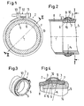
- the hose coupling shown has a tensionable around a longitudinal axis 1 around clamp 2, the edges 3 are closer to the longitudinal axis 1 than lying between the edges 3 area 4, and a tube 5, on one end portion 6, an end portion 7 of the hose 8 attachable and clamped by means of the clamp 2 is.
- the end portion 6 of the tube 5 is provided with a circumferential retaining rib 9, via which the end portion 7 of the hose 8 wegschiebbar and over the clamp 2 on the hose 8 can be tensioned, so that the hose 8 is clamped between the retaining rib 9 and clamp 2.
- the clamp 2 has an elastic clamping band 10 made of metal.
- the tension band 10 has the shape of a C-ring, on the ends of which clamping jaws 11 are fastened, for example by riveting or welding. Through the clamping jaws, a screw 12 is passed, the head rests against the one clamping jaw and which is screwed through a voltage applied to the other clamping jaw 11 nut 13.
- the region lying between the edges 3 of the tension band 10 has a distance from the hose 8 in the tensioned state of the clamp 2.
- the radially outer contour of the axial cross section of the retaining rib 9 is uniformly curved, preferably circular arc.
- the circumference of the retaining rib 9 at its in the assembled state of the tube 5 and tube 8 on the side of the free tube end lying in the tube 8 is smaller than the circumference at its other end.
- the cross-sectional contour of the tension band 10 between its edges 3 is also curved radially outwardly gleichze- ⁇ ig, preferably circular arc.
- the radius of curvature R 1 of the radially outer contour of the axial cross section of the retaining rib 9 is greater than the radius of curvature R 2 of the inner contour of the axial cross section of the clamping band 10.
- the tube 5 is made of metal, in particular light metal, here aluminum.
- Form the clamp 2 with the elastic clamping band 10 of uniform thickness of metal has the advantage that the clamping band 10 has a small area moment of inertia, so that it has a high elastic flexibility about perpendicular to its longitudinal axis 1 transverse axes. Their edges 3 can easily add an age- or pressure-related reduction in tube thickness and continue to clamp the tube 8 firmly to the tube 5, without the clamp 2 must be tightened to keep the connection tight. Further, the clamp 2 can yield or postpone changes in the dimensions of the tube 5 and the tube 8 as well as their own dimensions in a wide temperature fluctuation range of about -40 ° C to 200 ° C.
- the distance between the edges 3 of the clamping band 10 lying area of the hose 8 in the tensioned state of the clamp 2 also contributes to the fact that the radial compressive force of the clamping band edges 3 compared to that of the central region 4 between the edges 3 of the clamping band 10 is relatively high is and ensures a sufficiently high clamping effect in the region of the edges 3, but the tubing in the central region between the edges 3 is not or not too strong compressed and therefore subject to no permanent compression deformation.
- This distance can be easily adhered to, that the jaws 11th When reaching the distance, create one another or the clamping screw 12 can not be stretched beyond a torque at which the distance is reached, eg by means of a torque wrench.
- the uniform, in particular circular arc, curvature of the radially outer contour of the axial cross section of the retaining rib 9 prevents a high surface pressure in the end portion 7 of the hose 8, in contrast to an edged design of the retaining rib 9, and can be easily produced.
- the tube 8 can be easily slid up and over the retaining rib 9 , A heel 14 of the tube 5 or a wall of an aggregate, e.g. the cooler of a motor vehicle, to which the end portion 6 is tightly attached or formed, thereby limiting the Aufschubweg the hose 8.
- the tube is accordingly short and forms only a hose nozzle.
- the uniform, in particular circular arc, outwardly curved cross-sectional contour of the clamping band 10 between its edges 3 can also be easily produced and prevents too high surface pressures between tube 8 and strap 10, when the clamping band 10 is too tight.
Landscapes
- Engineering & Computer Science (AREA)
- General Engineering & Computer Science (AREA)
- Mechanical Engineering (AREA)
- Clamps And Clips (AREA)
- Joints That Cut Off Fluids, And Hose Joints (AREA)
- Rigid Pipes And Flexible Pipes (AREA)
Claims (8)
- Raccord express doté d'un collier (2), serrable autour de son axe longitudinal (1), dont les bords (3) se situent plus près de l'axe longitudinal (1) que la zone (4) située entre les bords(3),
et doté d'un tube (5), sur l'une des extrémités (6) duquel une extrémité (7) du tuyau (8) est montable et blocable au moyen du collier (2),
l'extrémité (6) du tube (5) étant dotée d'une nervure de retenue (9) périphérique, sur laquelle l'extrémité (7) du tuyau (8) peut glisser et au niveau de laquelle le collier (2) est serrable sur le tuyau (8), de sorte que le tuyau (8) est coincé entre la nervure de retenue (9) et le collier (2), le collier présentant une bande de serrage métallique périphérique de forme circulaire
caractérisé en ce que la bande de serrage (10) est élastique et d'épaisseur régulière et en ce qu'à l'état serré du collier (2), la zone (4) entre les bords (3) de la bande de serrage (10) présente un écartement par rapport au tuyau (8). - Raccord selon la revendication 1, caractérisé en ce que le contour extérieur radial de la section axiale de la nervure de retenue (9) est régulièrement bombé.
- Raccord selon l'une des revendications 1 ou 2, caractérisé en ce que le contour extérieur radial de la section axiale de la nervure de retenue (9) est en forme d'arc de cercle.
- Raccord selon la revendication 3, caractérisé en ce qu' à l'état assemblé du tube (5) et du tuyau (8), la circonférence de la nervure de retenue (9) du coté de son extrémité libre, située dans le tuyau (8), est inférieure à la circonférence au niveau de son autre extrémité.
- Raccord selon l'une des revendications 1 à 4, caractérisé en ce que le contour transversal extérieur de la bande de serrage (10) est régulièrement bombé de manière radiale vers l'extérieur entre ses bords (3).
- Raccord selon la revendication 5, caractérisé en ce que le bombement du contour transversal de la bande de serrage (10) est en forme d'arc de cercle.
- Raccord selon la revendication 2 et la revendication 6, caractérisé en ce que le rayon de courbure (R1) du contour radial extérieur de la section axiale de la nervure de retenue (9) est supérieur au rayon de courbure (R2) du contour interne de la section axiale de la bande de serrage (10).
- Raccord selon l'une des revendications 1 à 7, caractérisé en ce que le tube (5) est constitué de métal, en particulier de métal léger.
Applications Claiming Priority (2)
| Application Number | Priority Date | Filing Date | Title |
|---|---|---|---|
| DE10359799 | 2003-12-19 | ||
| DE10359799A DE10359799A1 (de) | 2003-12-19 | 2003-12-19 | Schlauchkupplung |
Publications (2)
| Publication Number | Publication Date |
|---|---|
| EP1544530A1 EP1544530A1 (fr) | 2005-06-22 |
| EP1544530B1 true EP1544530B1 (fr) | 2006-05-24 |
Family
ID=34485506
Family Applications (1)
| Application Number | Title | Priority Date | Filing Date |
|---|---|---|---|
| EP04024630A Expired - Lifetime EP1544530B1 (fr) | 2003-12-19 | 2004-10-15 | Raccord pour tuyaux flexibles |
Country Status (7)
| Country | Link |
|---|---|
| US (1) | US7322618B2 (fr) |
| EP (1) | EP1544530B1 (fr) |
| JP (1) | JP4063274B2 (fr) |
| KR (1) | KR100637935B1 (fr) |
| CA (1) | CA2490439C (fr) |
| DE (2) | DE10359799A1 (fr) |
| ES (1) | ES2260722T3 (fr) |
Families Citing this family (8)
| Publication number | Priority date | Publication date | Assignee | Title |
|---|---|---|---|---|
| DE102007008274A1 (de) | 2007-02-20 | 2008-08-21 | Bayerische Motoren Werke Aktiengesellschaft | Schlauchkupplung |
| DE102007035930A1 (de) | 2007-07-31 | 2009-02-05 | Bayerische Motoren Werke Aktiengesellschaft | Multi-Crimp-Schlauchschelle |
| US9534717B2 (en) | 2011-09-23 | 2017-01-03 | Norma U.S. Holding Llc | Hose clamp |
| EP2758701B1 (fr) | 2011-09-23 | 2019-05-08 | Norma U.S. Holding LLC | Dispositif de serrage de tuyau souple |
| DE102017107727A1 (de) * | 2017-04-10 | 2018-10-11 | Norma Germany Gmbh | Schlauchschelle |
| KR102552500B1 (ko) * | 2018-09-14 | 2023-07-07 | 현대자동차주식회사 | 호스 클램프 |
| DE102019105844A1 (de) * | 2019-03-07 | 2020-09-10 | Volkswagen Aktiengesellschaft | Rohr-Schlauch-Anordnung |
| US20240271737A1 (en) * | 2023-02-15 | 2024-08-15 | RB Distribution, Inc. | Repair boot for an air intake assembly |
Family Cites Families (19)
| Publication number | Priority date | Publication date | Assignee | Title |
|---|---|---|---|---|
| US684582A (en) * | 1901-03-15 | 1901-10-15 | Thomas H Barrett | Protector-clamp for air-hose. |
| US1204650A (en) * | 1912-10-19 | 1916-11-14 | Charles A Claflin | Hose-coupling. |
| US1072896A (en) * | 1913-04-02 | 1913-09-09 | Frank H Albee | Hose-clamp. |
| US2358575A (en) * | 1943-10-29 | 1944-09-19 | Jerry F Hurley | Hose clamp |
| GB1523201A (en) * | 1976-02-03 | 1978-08-31 | Smith & Johnson Keighley Ltd | Ring clamps |
| DE2919939A1 (de) * | 1979-05-17 | 1980-11-20 | Rasmussen Gmbh | Vorrichtung zum festspannen eines schlauches auf einem rohrfoermigen element |
| US4453746A (en) * | 1980-12-23 | 1984-06-12 | General Signal Corporation | Universal ferrule or band clamp hose fitting |
| US4537183A (en) * | 1983-04-08 | 1985-08-27 | Mentor Corporation | Connector device for connecting elastic tubing of an implantable device |
| SE445065B (sv) * | 1983-12-23 | 1986-05-26 | Allmaenna Brandredskapsaffaere | Slangklemma |
| FR2613786B1 (fr) * | 1987-04-09 | 1990-11-30 | Pont A Mousson | Collier a vis de serrage pivotante |
| US5195788A (en) * | 1990-01-30 | 1993-03-23 | Hans Oetiker | Insert member for use with hose clamp arrangements |
| DE4135017A1 (de) * | 1991-10-23 | 1993-04-29 | Ruppert Hans Peter | Verfahren, vorrichtung und kunststoffrohr-endstueck fuer die verbindung eines verformbaren kunststoffrohrs mit einem flexiblen schlauch |
| US5306051A (en) * | 1992-03-10 | 1994-04-26 | Hydrasearch Co., Inc. | Self-aligning and self-tightening hose coupling and method therefor |
| SE500904C2 (sv) * | 1993-09-15 | 1994-09-26 | Aba Sweden Ab | Anordning vid slangklämmor |
| DE19602907A1 (de) * | 1996-01-27 | 1997-07-31 | Bosch Gmbh Robert | Befestigungsanordnung einer Kraftstoffleitung auf einem Stutzen |
| US6170885B1 (en) * | 1996-10-10 | 2001-01-09 | The Gates Corporation | Self-adjusting at-least-twice-oriented polymer hose and tubing clamp |
| FR2776747B1 (fr) * | 1998-03-27 | 2000-06-02 | Hutchinson | Raccord encliquetable pour tuyau de transfert de fluide |
| US6641177B1 (en) * | 2000-08-25 | 2003-11-04 | Precision Design Concepts, Llc | Quick connect tube coupling and method of assembling the same |
| US6880862B2 (en) * | 2003-04-10 | 2005-04-19 | Dayco Products, Llc | Conductive tubular insert for a fuel transport system, and method |
-
2003
- 2003-12-19 DE DE10359799A patent/DE10359799A1/de not_active Withdrawn
-
2004
- 2004-10-15 DE DE502004000620T patent/DE502004000620D1/de not_active Expired - Lifetime
- 2004-10-15 ES ES04024630T patent/ES2260722T3/es not_active Expired - Lifetime
- 2004-10-15 EP EP04024630A patent/EP1544530B1/fr not_active Expired - Lifetime
- 2004-12-15 US US11/013,757 patent/US7322618B2/en not_active Expired - Lifetime
- 2004-12-16 CA CA002490439A patent/CA2490439C/fr not_active Expired - Fee Related
- 2004-12-17 JP JP2004366185A patent/JP4063274B2/ja not_active Expired - Fee Related
- 2004-12-17 KR KR1020040108241A patent/KR100637935B1/ko not_active Expired - Fee Related
Also Published As
| Publication number | Publication date |
|---|---|
| CA2490439C (fr) | 2008-02-12 |
| JP4063274B2 (ja) | 2008-03-19 |
| KR100637935B1 (ko) | 2006-10-23 |
| US20050134039A1 (en) | 2005-06-23 |
| ES2260722T3 (es) | 2006-11-01 |
| KR20050062448A (ko) | 2005-06-23 |
| CA2490439A1 (fr) | 2005-06-19 |
| EP1544530A1 (fr) | 2005-06-22 |
| US7322618B2 (en) | 2008-01-29 |
| DE10359799A1 (de) | 2005-07-21 |
| JP2005188743A (ja) | 2005-07-14 |
| DE502004000620D1 (de) | 2006-06-29 |
Similar Documents
| Publication | Publication Date | Title |
|---|---|---|
| DE69411935T2 (de) | Schlauchschelle | |
| EP2057401B1 (fr) | Systeme de positionnement prealable d'un collier de serrage a une extremite d'un flexible, notamment d'un flexible d'air de suralimentation ou d'eau de refroidissement | |
| DE112006001953B4 (de) | Schlauchspannschelle | |
| CH649613A5 (de) | Schlauchbandklemme. | |
| EP0769648B1 (fr) | Collier de serrage | |
| DE102004050300B4 (de) | Profilschelle | |
| DD281870A5 (de) | Schellenband | |
| DE102021115904A1 (de) | Flanschverbindungsanordnung für eine rohrleitung | |
| CH622597A5 (en) | Socket connection for pipes or pipe fittings | |
| EP1544530A1 (fr) | Raccord pour tuyaux flexibles | |
| DE102004006658B3 (de) | Verbindung einer Schelle mit einem Schlauch | |
| CH701049A1 (de) | Spannschelle für Rohrverbindungen. | |
| EP0498323B1 (fr) | Dispositif de connexion étanche pour embouts de tuyaux lisses | |
| DE19757751A1 (de) | Dichtungsvorrichtung zum abdichtenden Durchführen mindestens einer Leitung@ | |
| DE102009044807B4 (de) | Spannringsatz | |
| EP0498322B1 (fr) | Dispositif d'étanchéité pour l'assemblage de deux extrémités à tuyaux cylindriques et lisses | |
| EP0392148B1 (fr) | Raccord de tuyaux | |
| DE19939562C1 (de) | Spannbare Schelle | |
| DE202016000436U1 (de) | Rohrkupplung zum Verbinden von zwei röhrenförmigen Körpern | |
| EP1106895B1 (fr) | Dispositif de serrage | |
| EP1611387B1 (fr) | Raccord de tuyaux | |
| EP2288829B1 (fr) | Contour de serrage à joint d'étanchéité profilé | |
| DE3632164C2 (fr) | ||
| EP1340015B1 (fr) | Collier de serrage | |
| DE3347454A1 (de) | System zum verbinden von rohren |
Legal Events
| Date | Code | Title | Description |
|---|---|---|---|
| PUAI | Public reference made under article 153(3) epc to a published international application that has entered the european phase |
Free format text: ORIGINAL CODE: 0009012 |
|
| 17P | Request for examination filed |
Effective date: 20050324 |
|
| AK | Designated contracting states |
Kind code of ref document: A1 Designated state(s): AT BE BG CH CY CZ DE DK EE ES FI FR GB GR HU IE IT LI LU MC NL PL PT RO SE SI SK TR |
|
| AX | Request for extension of the european patent |
Extension state: AL HR LT LV MK |
|
| GRAP | Despatch of communication of intention to grant a patent |
Free format text: ORIGINAL CODE: EPIDOSNIGR1 |
|
| GRAS | Grant fee paid |
Free format text: ORIGINAL CODE: EPIDOSNIGR3 |
|
| AKX | Designation fees paid |
Designated state(s): DE ES FR GB IT SE |
|
| GRAA | (expected) grant |
Free format text: ORIGINAL CODE: 0009210 |
|
| AK | Designated contracting states |
Kind code of ref document: B1 Designated state(s): DE ES FR GB IT SE |
|
| PG25 | Lapsed in a contracting state [announced via postgrant information from national office to epo] |
Ref country code: IT Free format text: LAPSE BECAUSE OF FAILURE TO SUBMIT A TRANSLATION OF THE DESCRIPTION OR TO PAY THE FEE WITHIN THE PRESCRIBED TIME-LIMIT;WARNING: LAPSES OF ITALIAN PATENTS WITH EFFECTIVE DATE BEFORE 2007 MAY HAVE OCCURRED AT ANY TIME BEFORE 2007. THE CORRECT EFFECTIVE DATE MAY BE DIFFERENT FROM THE ONE RECORDED. Effective date: 20060524 |
|
| REG | Reference to a national code |
Ref country code: GB Ref legal event code: FG4D Free format text: NOT ENGLISH |
|
| REF | Corresponds to: |
Ref document number: 502004000620 Country of ref document: DE Date of ref document: 20060629 Kind code of ref document: P |
|
| GBT | Gb: translation of ep patent filed (gb section 77(6)(a)/1977) |
Effective date: 20060628 |
|
| REG | Reference to a national code |
Ref country code: SE Ref legal event code: TRGR |
|
| REG | Reference to a national code |
Ref country code: ES Ref legal event code: FG2A Ref document number: 2260722 Country of ref document: ES Kind code of ref document: T3 |
|
| ET | Fr: translation filed | ||
| PLBE | No opposition filed within time limit |
Free format text: ORIGINAL CODE: 0009261 |
|
| STAA | Information on the status of an ep patent application or granted ep patent |
Free format text: STATUS: NO OPPOSITION FILED WITHIN TIME LIMIT |
|
| 26N | No opposition filed |
Effective date: 20070227 |
|
| PGFP | Annual fee paid to national office [announced via postgrant information from national office to epo] |
Ref country code: GB Payment date: 20101021 Year of fee payment: 7 Ref country code: IT Payment date: 20101025 Year of fee payment: 7 |
|
| GBPC | Gb: european patent ceased through non-payment of renewal fee |
Effective date: 20121015 |
|
| PG25 | Lapsed in a contracting state [announced via postgrant information from national office to epo] |
Ref country code: GB Free format text: LAPSE BECAUSE OF NON-PAYMENT OF DUE FEES Effective date: 20121015 |
|
| PG25 | Lapsed in a contracting state [announced via postgrant information from national office to epo] |
Ref country code: IT Free format text: LAPSE BECAUSE OF NON-PAYMENT OF DUE FEES Effective date: 20121015 |
|
| REG | Reference to a national code |
Ref country code: FR Ref legal event code: PLFP Year of fee payment: 12 |
|
| REG | Reference to a national code |
Ref country code: DE Ref legal event code: R082 Ref document number: 502004000620 Country of ref document: DE Representative=s name: PATENTANWAELTE OLBRICHT, BUCHHOLD, KEULERTZ PA, DE |
|
| REG | Reference to a national code |
Ref country code: FR Ref legal event code: PLFP Year of fee payment: 13 |
|
| PGFP | Annual fee paid to national office [announced via postgrant information from national office to epo] |
Ref country code: ES Payment date: 20161011 Year of fee payment: 13 |
|
| REG | Reference to a national code |
Ref country code: FR Ref legal event code: PLFP Year of fee payment: 14 |
|
| REG | Reference to a national code |
Ref country code: FR Ref legal event code: PLFP Year of fee payment: 15 |
|
| REG | Reference to a national code |
Ref country code: ES Ref legal event code: FD2A Effective date: 20181221 |
|
| PG25 | Lapsed in a contracting state [announced via postgrant information from national office to epo] |
Ref country code: ES Free format text: LAPSE BECAUSE OF NON-PAYMENT OF DUE FEES Effective date: 20171016 |
|
| PGFP | Annual fee paid to national office [announced via postgrant information from national office to epo] |
Ref country code: SE Payment date: 20211027 Year of fee payment: 18 |
|
| REG | Reference to a national code |
Ref country code: SE Ref legal event code: EUG |
|
| PG25 | Lapsed in a contracting state [announced via postgrant information from national office to epo] |
Ref country code: SE Free format text: LAPSE BECAUSE OF NON-PAYMENT OF DUE FEES Effective date: 20221016 |
|
| PGFP | Annual fee paid to national office [announced via postgrant information from national office to epo] |
Ref country code: FR Payment date: 20231025 Year of fee payment: 20 Ref country code: DE Payment date: 20231027 Year of fee payment: 20 |
|
| REG | Reference to a national code |
Ref country code: DE Ref legal event code: R071 Ref document number: 502004000620 Country of ref document: DE |