EP1544515A1 - Arretierelement - Google Patents
Arretierelement Download PDFInfo
- Publication number
- EP1544515A1 EP1544515A1 EP04029185A EP04029185A EP1544515A1 EP 1544515 A1 EP1544515 A1 EP 1544515A1 EP 04029185 A EP04029185 A EP 04029185A EP 04029185 A EP04029185 A EP 04029185A EP 1544515 A1 EP1544515 A1 EP 1544515A1
- Authority
- EP
- European Patent Office
- Prior art keywords
- housing
- locking element
- sleeve
- locking
- element according
- Prior art date
- Legal status (The legal status is an assumption and is not a legal conclusion. Google has not performed a legal analysis and makes no representation as to the accuracy of the status listed.)
- Granted
Links
- 238000005520 cutting process Methods 0.000 claims abstract description 9
- 230000006835 compression Effects 0.000 claims description 49
- 238000007906 compression Methods 0.000 claims description 49
- 238000009434 installation Methods 0.000 claims description 35
- 238000004080 punching Methods 0.000 claims description 6
- 230000005540 biological transmission Effects 0.000 claims description 5
- 238000000034 method Methods 0.000 claims description 3
- 238000003856 thermoforming Methods 0.000 claims 1
- 238000004519 manufacturing process Methods 0.000 description 4
- 239000002689 soil Substances 0.000 description 3
- OKTJSMMVPCPJKN-UHFFFAOYSA-N Carbon Chemical compound [C] OKTJSMMVPCPJKN-UHFFFAOYSA-N 0.000 description 2
- 229910052799 carbon Inorganic materials 0.000 description 2
- 230000007935 neutral effect Effects 0.000 description 2
- 230000002411 adverse Effects 0.000 description 1
- 238000005266 casting Methods 0.000 description 1
- 239000003795 chemical substances by application Substances 0.000 description 1
- 238000002788 crimping Methods 0.000 description 1
- 238000006073 displacement reaction Methods 0.000 description 1
- 238000003780 insertion Methods 0.000 description 1
- 230000037431 insertion Effects 0.000 description 1
- 239000010410 layer Substances 0.000 description 1
- 239000000463 material Substances 0.000 description 1
- 239000002184 metal Substances 0.000 description 1
- 238000003825 pressing Methods 0.000 description 1
- 238000010791 quenching Methods 0.000 description 1
- 230000000171 quenching effect Effects 0.000 description 1
- 230000003319 supportive effect Effects 0.000 description 1
- 239000002344 surface layer Substances 0.000 description 1
- 238000005496 tempering Methods 0.000 description 1
- 230000007704 transition Effects 0.000 description 1
Images




Classifications
-
- F—MECHANICAL ENGINEERING; LIGHTING; HEATING; WEAPONS; BLASTING
- F16—ENGINEERING ELEMENTS AND UNITS; GENERAL MEASURES FOR PRODUCING AND MAINTAINING EFFECTIVE FUNCTIONING OF MACHINES OR INSTALLATIONS; THERMAL INSULATION IN GENERAL
- F16H—GEARING
- F16H63/00—Control outputs from the control unit to change-speed- or reversing-gearings for conveying rotary motion or to other devices than the final output mechanism
- F16H63/02—Final output mechanisms therefor; Actuating means for the final output mechanisms
- F16H63/30—Constructional features of the final output mechanisms
- F16H63/38—Detents
-
- G—PHYSICS
- G05—CONTROLLING; REGULATING
- G05G—CONTROL DEVICES OR SYSTEMS INSOFAR AS CHARACTERISED BY MECHANICAL FEATURES ONLY
- G05G5/00—Means for preventing, limiting or returning the movements of parts of a control mechanism, e.g. locking controlling member
- G05G5/06—Means for preventing, limiting or returning the movements of parts of a control mechanism, e.g. locking controlling member for holding members in one or a limited number of definite positions only
Definitions
- the present invention relates to a locking element with which a movable arranged actuator, such as a shift rod in a manual transmission for vehicles, is position fixable.
- the locking element comprises a stationary in a recording of a component, for example in the housing of the gearbox pressed-in, hollow cylindrical housing in which a Snap sleeve is guided longitudinally displaceable.
- the likewise hollow cylindrical running Detent sleeve forms the front side at the end facing away from the housing a closed spherical cap, which in an end position, a locking position, positively locked in a recess of the actuating element.
- a compression spring integrated which acts on the locking sleeve in the direction of the actuating element is, wherein between the latching sleeve and the housing a stroke limitation is provided.
- a locking element which is a shift locking device for forms a change gear.
- the structure comprises a housing with a relative large wall thickness in which a locking pin is guided longitudinally displaceable.
- a compression spring within the locking element between the bottom of the Housing and a front side of the locking pin used.
- the locking element in the gear housing is a first Tangentialstatt, which is inserted into a receiving bore of the transmission housing and at the same time locally engages in a recess of the housing of the locking element.
- a second tangential pin is inserted into the locking element such that this is inserted into a bore of the housing of the locking element and at the same time engages in a recess of the locking pin.
- the recess the locking bolt extends over a length which is the diameter of Tangentialstattes significantly exceeds and thus allows an actuating movement the locking pin, which is limited by the length of the recess.
- the structure of this known locking element includes exclusively machined components that alternatively formed as castings can be. Associated with this results in a relatively large required Installation space and high production costs.
- the locking element comprises a pot-shaped, non-cutting manufactured and hardened housing, in the bottom of an opening introduced is.
- the opening is formed by a constriction formed as a bend or as a board limited.
- the housing is a hollow cylindrical designed, also inserted snap-on sleeve used. To achieve an optimal Guiding the detent sleeve in the housing is this in axially separate sections, d. H. on the inner wall of the housing and in the area of the constriction led from the bottom of the housing.
- the invention enables the representation of a locking element, in which neither for the housing still a crimping is required for the locking sleeve.
- the Constriction, or a retaining collar for the Hubbegrenzung and leadership of Snap sleeve is inventively without cutting, preferably by a Punching or punching produced, to form an opening in the bottom of the Housing.
- the opening of the soil continue to be formed as a circumferential offset, wherein the bent collar having an extended collar also as a passage too is denote.
- the representation of a shape and tolerance optimized constriction may continue be realized even with larger wall thicknesses of the soil, which advantageously extends the guide sleeve in the area the constriction sets.
- the invention includes the housing as well as the locking sleeve to cure at the same time. If a finishing is required, this can take the hardened components. This allows the previously used induction-tempering or high-frequency starting omitted.
- the inventive measures the production of a dimensionally accurate Constricting or retaining collar ensures, in conjunction with or alternatively to a hardened housing and a hardened locking sleeve is the Improved functionality of the locking element. It also turns out to be a cost effective Production of the locking element, the same today Customer requirements met.
- the housing can be advantageous with a higher insertion force a tighter fit, a transition fit or a press fit, for example in a bore of the Gearbox be permanently positioned safely without risk of plastic deformation of the housing.
- This tight fit compensated advantageous disadvantageous tolerance layers that prevent a permanent defined installation position or adversely affect the function of the locking element. simultaneously allows the hardened housing by a punched in the bottom one Opening to bring.
- a required for the function of the locking element installation play between the locking sleeve and the housing provides that this is 5 0.35 mm.
- the installation play "S 1 " between the crank or the board of the housing and the latching sleeve agrees advantageously with the installation clearance "S 2 ", which is set between the end zone of the stepped, radially outwardly directed portion of the latching sleeve and the inner wall of the housing.
- the non-cutting method for producing the housing and the locking sleeve allows without a rework the observance of the installation play both between the inner wall of the housing and the radially expanded portion the locking sleeve and between the constriction of the housing and the locking sleeve.
- the advantageous closely designed installation play between the guide sections the locking element avoids tilting of the locking sleeve opposite the housing and ensures optimal function of the Arretierelemntes.
- a case hardening provided.
- an improved rigidity housing may have an increased rigidity Pressing force into a receptacle, such as a bore of the transmission housing be pressed to achieve a secure fit.
- the case hardened case by punching in the ground an exact, crack-free, dimensionally exactly tuned opening introduced be, at the edge zone or constriction, the locking sleeve is guided.
- the case-hardened housing advantageous with a correspondingly hardened detent sleeve can be combined.
- Another preferred embodiment feature of the invention relates on the mounting position of the compression spring.
- the compression spring is supported directly on the component, in its recording the locking element is pressed.
- This is the hardened housing with a tubular end portion without inner stop for the compression spring in one Drill hole of the component, for example, a transmission housing pressed.
- the spring end In the installation position is the spring end on a frontal support of the component supported.
- An alternative embodiment of the compression spring points to that of the latching sleeve facing away from a conically outwardly directed spring end, whose Endwindung is guided on the inner wall of the housing. This turns out a centering of the two spring ends within the locking element, connected with a straightforward introduction of force, the risk of tipping the Detent sleeve stops.
- the invention also includes a locking element in which the compression spring on the housing side cooperates with a holding element.
- This is the holding element Fixed and secured at the end to the inner wall of the housing a centered mounting position of the compression spring.
- the holding element is with a retaining fuse in conjunction with the completed locking element the compression spring secured against loss in the locking element and positioned at the same time represents an effective transport security.
- the holding element is advantageously provided with a security clip, up to a defined Holding force the compression spring positioned relative to the housing. Im installed Condition loosens the retaining clip in a first stroke of the Rasthülse opposite the housing and dodges, causing the Spring end of the compression spring can be supported on the support of the component, in the the housing is pressed. The retaining clip becomes the function of the locking element not disabled.
- the invention also offers a disk-like designed retaining element that with a limited holding force on the inner wall of the Housing is supported. In the operating state, with a shift of Detent sleeve and a thus increased supporting force of the compression spring on the holding element this is axially displaced to the support on the component, in the the locking element is pressed.
- the retaining element is advantageous pressure spring side provided with a centering pin, the mounting position of the compression spring Are defined.
- the invention includes, for example formed from sheet metal ring elements.
- the position-fixed installation position the retaining element can preferably be supported by means of a bond.
- the invention also provides that the compression spring with a spring end is supported on a chipless molded-on board of the housing.
- the housing integral with a collar to be provided for the installation of a washer inserted into the locking sleeve is determined. This disc is intended to support the compression spring.
- the structure of the locking element according to the invention by means of a Press Association is safely pressed, and one important for the function having large spring length of the compression spring, can with the holding element, as a precomplete assembly are joined together.
- FIG. 1 shows the locking element 1a in an installed position, in which it is in a receptacle 2, a bore in a component 3 is pressed.
- the locking element 1a comprises a top-like designed housing 4a whose outer contour or lateral surface is preferably case hardened, so that the locking element 1a with an enlarged press-in force without plastic deformation of the Housing 4a can be pressed into the receptacle 2.
- the pot-trained Housing 4a forms a bottom 5 in which by a punching centric a formed as an opening 6 constriction 28 is introduced, the outside of a board 7 is limited.
- a locking sleeve 8 slidably inserted sliding.
- a hollow body forming latching sleeve 8 has a step 10 which, in conjunction with the board. 7 of the bottom 5 forms a stroke limiter 11.
- Front side of the component 3 facing away from the locking sleeve 8 a spherical cap 12, according to Figure 2 for fixing the position of an axially movable control element 13 in one End position positively locked in a corresponding recess 14.
- the detent sleeve 8 is guided in the housing 4a while maintaining "S 1 , S 2 , S 3 " mounting apertures.
- the installation play “S 1 " is in the region of the constriction 28 between the board 7 and the locking sleeve 8 a.
- Via a radially expanded, end-to-outside annular end zone 29, the locking sleeve 8 is associated with the installation play "S 2 " of the inner wall 9 of the housing 4a.
- the further installation clearance "S 3 " which exceeds the degree of installation play “S 1 , S 2 " is provided in the area between the constriction 28, the shelf 7 of the housing 4 a and the end zone 29.
- compression spring 15a By means of an integrated in the locking element 1a compression spring 15a is the latching sleeve 8 kraftbeaufschlagt. A first spring end 16 is directly in the Locking sleeve 8 centered. Via a second spring end 17a, the compression spring is supported 15a on a support 18 of the component 3 from. An exact installation position of Securing compression spring 15a, the spring end 17a is conical, so that the Compression spring 15a with a spring end on the inner wall 9 of the housing 4a is guided.
- FIG. 2 shows the locking element 1b with one, except for the compression spring 15b matching structure of the locking element 1a according to Figure 1.
- the description Figure 2 relies exclusively on the difference parts opposite the locking element 1a.
- the compression spring 15b, with the locking sleeve 8 frictionally locked in the recess 14 of the actuating element 13 is in the housing 4a is guided in a holding element 19.
- the preferred plastic manufactured, fixed in position on the inner wall 9 of the housing 4a retaining element 19 allows the use of an exclusively cylindrical wound Compression spring 15b.
- the holding element 19 is provided with at least one retaining clip 20 provided to the component 3 side facing an axial stop for the Spring end 17b of the compression spring 15b forms.
- the retaining clip 20 forms a transport safety device, d. H.
- the one limited holding power forming retaining clip 20 is designed so that in the installed state, for example at a first stroke, d. H. an adjusting movement of Detent sleeve 8 evades in the direction of the component 3 of the retaining clip 20 and thus a support of the spring end 17b on the support 18 of the housing 3 allows.
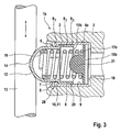
- the locking member 1b is shown, provided with a disc-like designed holding member 19 b, the with a limited holding force the inner wall 9 of the housing 4a is supported.
- the retaining element 19b this is axially up to the support 18 on the component. 3 displaced in which the locking element 1c is pressed.
- the retaining element 19b pressure spring side provided with a centering pin 21, the form-fitting of the Spring end 17b of the compression spring 15b is enclosed.
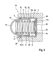
- the locking element 1d comprises a compression spring 15b, in which associated with the spring end 17b of a disc 25 which on a collar 24 of the Housing 4a is fixed in position. at the centrally located centering 26 of the Disk 25, the compression spring 15b is positioned.
- FIG. 6 shows the housing 4b in conjunction with the detent sleeve 8, in which the housing 4b has a doubling 31 at the end to form a constriction 28. Due to the non-cutting formed on the housing 4b doubling 31 provides a stroke limit for the locking sleeve 8 a.
- FIG. 6 also shows the end zone 29 in the radially widened region of the latching sleeve 8, which in the installation position is supported on the inner wall 9 of the housing 4b. Regardless of the position of the detent sleeve 8, the end zone 29 is in each case axially spaced from the further guidance of the detent sleeve 8 in the housing 4b, which adjusts in the region of the constriction 28 formed as a doubling 31.
- the required for the function installation play “S 1 , S 2 ,” in the area of each guide is designed to each other largely dimensionally consistent.
- the further installation play “S 3 " between the end zone 29 and the constriction 28 exceeds the dimensional play "S 1 , S 2 ".
- the locking element 1e partially depicted in FIG. 7 includes a housing 4c which, in the region of the opening, widens a constriction 28 designed as a crank 27, on which the detent sleeve 8 is guided in compliance with the installation play "S 1 ".
- the crank 27 likewise forms a desired extended axial guidance of the detent sleeve 8, which is assigned within the housing 4c via the end zone 29 to the inner wall 9 with the installation play "S 2 ".
- the locking sleeve 8 has the front side on the outer periphery in the region of the end zone 29 has a radius 30, which prevents a further supportive measure disadvantageous clamping of the latching sleeve 8 within the housing 4c.
- the enlarged view of the locking element 1e clarifies the opposite of the mounting spectacles "S 1 , S 2 " significantly larger installation play "S 3 ".
Landscapes
- Engineering & Computer Science (AREA)
- General Engineering & Computer Science (AREA)
- Physics & Mathematics (AREA)
- General Physics & Mathematics (AREA)
- Automation & Control Theory (AREA)
- Mechanical Engineering (AREA)
- Snaps, Bayonet Connections, Set Pins, And Snap Rings (AREA)
- Insertion Pins And Rivets (AREA)
Abstract
Description
- Figur 1
- in einem Längsschnitt ein erfindungsgemäßes Arretierelement, bei dem die integrierte Druckfeder unmittelbar an einem Bauteil abgestützt ist, in das das Arretierelement eingepresst ist;
- Figur 2
- ein Arretierelement, versehen mit einer zylindrisch gestalteten Druckfeder, das an einem Ende mit einem Halteelement zusammenwirkt;
- Figur 3
- das Arretierelement gemäß Figur 2, mit einem alternativ gestalteten Halteelement;
- Figur 4
- eine alternative Abstützung eines Federende der Druckfeder des Arretierelementes an einem Bord des Gehäuses;
- Figur 5
- die Abstützung eines Federende der Druckfeder an einer Scheibe, die an einem Kragen des Gehäuses fixiert ist;
- Figur 6
- in einer Schnittdarstellung das Gehäuse in Verbindung mit der Rasthülse;
- Figur 7
- in einer vergrößerten Darstellung einen Ausschnitt eines erfindungsgemäßen Arretierelementes, das insbesondere die Führungsbereiche zwischen dem Gehäuse und der Rasthülse darstellt.
- 1a
- Arretierelement
- 1b
- Arretierelement
- 1c
- Arretierelement
- 1d
- Arretierelement
- 1e
- Arretierelement
- 2
- Aufnahme
- 3
- Bauteil
- 4a
- Gehäuse
- 4b
- Gehäuse
- 4c
- Gehäuse
- 5
- Boden
- 6
- Öffnung
- 7
- Bord
- 8
- Rasthülse
- 9
- Innenwandung
- 10
- Stufe
- 11
- Hubbegrenzung
- 12
- Kugelkalotte
- 13
- Stellelement
- 14
- Ausnehmung
- 15a
- Druckfeder
- 15b
- Druckfeder
- 16
- Federende
- 17a
- Federende
- 17b
- Federende
- 18
- Auflage
- 19a
- Halteelement
- 19b
- Halteelement
- 20
- Halteclip
- 21
- Halteclip
- 22
- Zentrierzapfen
- 23
- Bord
- 24
- Kragen
- 25
- Scheibe
- 26
- Zentrierung
- 27
- Kröpfung
- 28
- Einschnürung
- 29
- Endzone
- 30
- Radius
- 31
- Doppelung
- "S1"
- Einbauspiel
- "S2"
- Einbauspiel
- "S3"
- Einbauspiel
Claims (17)
- Arretierelement, bestimmt zur Lagefixierung und / oder Betätigung eines beweglichen Stellelementes (13), beispielsweise einer Schaltstange in einem Schaltgetriebe für Fahrzeuge, umfassend ein ortsfest in eine Aufnahme (2) eines Bauteils (3) angepresstes, hohlzylindrisches Gehäuse (4a bis 4c), in dem eine stirnseitig eine Kugelkalotte (12) bildende Rasthülse (8) gleitgelagert und längsverschiebbar geführt ist, wobei die Kugelkalotte (12) in einer Arretierstellung formschlüssig in eine Ausnehmung (14) des Stellelementes (13) kraftschlüssig verrastet und dazu eine in dem Arretierelement (1a bis 1e) integrierte Druckfeder (15a, 15b) gegen die Rasthülse (8) vorgespannt ist und zwischen der Rasthülse (8) und dem Gehäuse (4) eine Hubbegrenzung (11) vorgesehen ist, dadurch gekennzeichnet, dass ein Boden (5) des topfartig gestalteten, spanlos hergestellten, gehärteten Gehäuse (4a bis 4c) eine Öffnung (6) aufweist, deren Randzone eine als Kröpfung (27) oder als Bord (7) ausgebildete Einschnürung (28) umfasst und die einen Hohlkörper bildende, spanlos hergestellte Rasthülse (8) an der Einschnürung (28) sowie an einer Innenwandung (9) des Gehäuses (4) geführt ist, und dabei die Rasthülse (8) über eine radial vorstehende, endseitig einer nach außen gerichteten Stufe (10) zugeordneten Endzone (29) an der Innenwandung (9) des Gehäuses (4) abgestützt ist und als Hubbegrenzung (11) die radial nach innen gerichtete Einschnürung (28) des Gehäuses (4a bis 4c) die Stufe (10) der Rasthülse (8) übergreift.
- Arretierelement nach Anspruch 1, wobei der Bord (7) in dem Boden (5) des Gehäuses (4a) eine durch Stanzen eingebrachte Öffnung (6) begrenzt.
- Arretierelement nach Anspruch 1, bei dem die Kröpfung (27) durch Stanzen oder ein Tiefziehverfahren spanlos in den Boden (5) des Gehäuses (4c) eingebracht ist.
- Arretierelement nach Anspruch 1, bei dem die Endzone (29) der nach außen gerichteten Stufe (10) der Rasthülse (8) stirnseitig an einem Außenumfang einen Radius (30) oder eine Phase bildet.
- Arretierelement nach Anspruch 1, bei dem ein Einbauspiel "S1, S2" von ≤ 0,35 mm zwischen der Rasthülse (8) und der Kröpfung (27) oder dem Bord (7) im Bereich des Bodens (5) einerseits und der Innenwandung (9) des Gehäuses (4a bis 4c) andererseits vorgesehen ist.
- Arretierelement nach Anspruch 1, wobei sich ein im Abschnitt zwischen der Einschnürung (28) und der Endzone (29) einstellendes Einbauspiel "S3" zwischen der Rasthülse (8) und dem Gehäuses (4a bis 4c) das Einbauspiel "S1 bzw. S2" übertrifft.
- Arretierelement nach Anspruch 1, bei dem das Gehäuse (4a bis 4c) außenseitig vollständig einsatzgehärtet ist.
- Arretierelement nach Anspruch 1, deren Rasthülse (8) zumindest bereichsweise einsatzgehärtet ist.
- Arretierelement nach Anspruch 1, deren Gestaltung und Auslegung eine gleichzeitige Härtung des Gehäuse (4a bis 4c) und der Rasthülse (8) ermöglicht.
- Arretierelement nach Anspruch 1, wobei die Druckfeder (15a) in der Einbaulage mit einem ersten Federende (16) in der Rasthülse (8) geführt ist und ein zweites Federende (17a) stirnseitig an einer Auflage (18) des Bauteils (3) abgestützt ist, in dessen Aufnahme (2) das Arretierelement (1a) eingepresst ist.
- Arretierelement nach Anspruch 10, bei dem die Druckfeder (15a) mit einem konisch gestalteten Federende (17a) an der Innenwandung (9) des Gehäuses (4a) geführt ist.
- Arretierelement nach Anspruch 1, deren Druckfeder (15b) mit einem an dem Gehäuse (4a) lagefixierten Halteelement (19a) zusammenwirkt, mit dem die Druckfeder (15b) zentriert und ein Halteclip (20) des Halteelementes (19a) eine Transportsicherung und gleichzeitig eine verliergesicherte Anordnung der Druckfeder (15b) in dem Gehäuse (4a) ermöglicht.
- Arretierelement nach Anspruch 1, wobei der Druckfeder (15b) ein in dem Gehäuse (4a) lagefixiertes Halteelement (19b) mit einem Zentrierzapfen (21) zugeordnet ist.
- Arretierelement nach Anspruch 12 oder nach Anspruch 13, die ein aus Kunststoff hergestelltes, ein Ringelement bildendes Halteelement (19a,19b), einschließt, das an der Innenwandung (9) des Gehäuses (4a) lagepositioniert ist.
- Arretierelement nach Anspruch 1, wobei die Druckfeder (15b) mit dem Federende (17b) an einem einstückig mit dem Gehäuse (4a) verbundenen Bord (23) abgestützt ist.
- Arretierelement nach Anspruch 1, deren Gehäuse (4a) einen Kragen (24) aufweist, an dem eine Scheibe (25) abgestützt ist, die mit der Druckfeder (15b) zusammenwirkt.
- Arretierelement nach Anspruch 1, das spanlos, bevorzugt durch ein Tiefziehverfahren hergestellte Bauteile, Gehäuse (4a bis 4c) und Rasthülse (8) einschließt, die ohne Nacharbeit gemeinsam mit der Druckfeder (15a, 15b) zu einer Baueinheit, dem Arretierelement (1a, 1b) kompiettierbar sind.
Applications Claiming Priority (2)
| Application Number | Priority Date | Filing Date | Title |
|---|---|---|---|
| DE2003159067 DE10359067A1 (de) | 2003-12-16 | 2003-12-16 | Arretierelement |
| DE10359067 | 2003-12-16 |
Publications (2)
| Publication Number | Publication Date |
|---|---|
| EP1544515A1 true EP1544515A1 (de) | 2005-06-22 |
| EP1544515B1 EP1544515B1 (de) | 2006-09-27 |
Family
ID=34485420
Family Applications (1)
| Application Number | Title | Priority Date | Filing Date |
|---|---|---|---|
| EP20040029185 Expired - Lifetime EP1544515B1 (de) | 2003-12-16 | 2004-12-09 | Arretierelement |
Country Status (2)
| Country | Link |
|---|---|
| EP (1) | EP1544515B1 (de) |
| DE (2) | DE10359067A1 (de) |
Cited By (3)
| Publication number | Priority date | Publication date | Assignee | Title |
|---|---|---|---|---|
| DE102006042964A1 (de) * | 2006-09-13 | 2008-03-27 | Schaeffler Kg | Arretierelement zur Sicherung der Position eines verschiebbaren und/oder schwenkbaren Bauteils |
| CN105937616A (zh) * | 2016-06-27 | 2016-09-14 | 常州光洋轴承股份有限公司 | 用于汽车变速箱的整体式滑柱组件 |
| US10088042B2 (en) * | 2015-08-05 | 2018-10-02 | Fico Triad, S.A. | Shift selector mechanism for motor vehicle transmissions |
Families Citing this family (5)
| Publication number | Priority date | Publication date | Assignee | Title |
|---|---|---|---|---|
| DE102008039011B4 (de) | 2008-08-21 | 2020-01-16 | MAE Maschinen- u. Apparatebau Götzen GmbH | Druckspeicherlose hydraulische Antriebsanordnung sowie Verfahren zum druckspeicherlosen hydraulischen Antreiben eines Verbrauchers |
| CN102788145B (zh) * | 2012-07-27 | 2015-03-11 | 长城汽车股份有限公司 | 一种选挡回位机构 |
| DE102012213523A1 (de) | 2012-08-01 | 2014-02-06 | Schaeffler Technologies AG & Co. KG | Schalteinheit |
| DE102014214126A1 (de) * | 2014-07-21 | 2016-01-21 | Schaeffler Technologies AG & Co. KG | Schaltsperre für ein Schaltgetriebe |
| DE102016201830A1 (de) | 2016-02-08 | 2017-08-10 | Schaeffler Technologies AG & Co. KG | Scharniermechanismus |
Citations (3)
| Publication number | Priority date | Publication date | Assignee | Title |
|---|---|---|---|---|
| DE3525989A1 (de) * | 1984-07-26 | 1986-01-30 | Zahnradfabrik Friedrichshafen | Gangschalteinrichtung |
| DE4118930A1 (de) * | 1991-06-08 | 1992-12-10 | Zahnradfabrik Friedrichshafen | Schaltsperrvorrichtung fuer ein geschwindigkeits- und fahrtrichtungswechselgetriebe |
| DE10059377A1 (de) * | 2000-11-30 | 2002-06-27 | Ina Schaeffler Kg | Wähl- und Schalteinrichtung zum Wählen und Schalten von Gängen eines Getriebes |
Family Cites Families (7)
| Publication number | Priority date | Publication date | Assignee | Title |
|---|---|---|---|---|
| DE3047117C2 (de) * | 1980-12-13 | 1983-11-24 | Zahnradfabrik Friedrichshafen Ag, 7990 Friedrichshafen | Rastvorrichtung |
| DE9309025U1 (de) * | 1993-06-17 | 1993-09-30 | INA Wälzlager Schaeffler KG, 91074 Herzogenaurach | Schaltarretierung |
| DE9319480U1 (de) * | 1993-12-20 | 1994-03-17 | INA Wälzlager Schaeffler KG, 91074 Herzogenaurach | Arretierelement |
| DE9407205U1 (de) * | 1994-04-30 | 1994-06-23 | INA Wälzlager Schaeffler KG, 91074 Herzogenaurach | Schaltarretierung |
| DE9418971U1 (de) * | 1994-11-25 | 1995-01-26 | INA Wälzlager Schaeffler KG, 91074 Herzogenaurach | Reibungsarm abgestützte Druckfeder |
| JPH10100710A (ja) * | 1996-09-30 | 1998-04-21 | Aisin Ee I Kk | 操作レバーの復帰用ピン |
| DE10221975A1 (de) * | 2002-05-17 | 2003-11-27 | Ina Schaeffler Kg | Arretierung |
-
2003
- 2003-12-16 DE DE2003159067 patent/DE10359067A1/de not_active Withdrawn
-
2004
- 2004-12-09 EP EP20040029185 patent/EP1544515B1/de not_active Expired - Lifetime
- 2004-12-09 DE DE200450001587 patent/DE502004001587D1/de not_active Expired - Lifetime
Patent Citations (3)
| Publication number | Priority date | Publication date | Assignee | Title |
|---|---|---|---|---|
| DE3525989A1 (de) * | 1984-07-26 | 1986-01-30 | Zahnradfabrik Friedrichshafen | Gangschalteinrichtung |
| DE4118930A1 (de) * | 1991-06-08 | 1992-12-10 | Zahnradfabrik Friedrichshafen | Schaltsperrvorrichtung fuer ein geschwindigkeits- und fahrtrichtungswechselgetriebe |
| DE10059377A1 (de) * | 2000-11-30 | 2002-06-27 | Ina Schaeffler Kg | Wähl- und Schalteinrichtung zum Wählen und Schalten von Gängen eines Getriebes |
Cited By (3)
| Publication number | Priority date | Publication date | Assignee | Title |
|---|---|---|---|---|
| DE102006042964A1 (de) * | 2006-09-13 | 2008-03-27 | Schaeffler Kg | Arretierelement zur Sicherung der Position eines verschiebbaren und/oder schwenkbaren Bauteils |
| US10088042B2 (en) * | 2015-08-05 | 2018-10-02 | Fico Triad, S.A. | Shift selector mechanism for motor vehicle transmissions |
| CN105937616A (zh) * | 2016-06-27 | 2016-09-14 | 常州光洋轴承股份有限公司 | 用于汽车变速箱的整体式滑柱组件 |
Also Published As
| Publication number | Publication date |
|---|---|
| DE10359067A1 (de) | 2005-07-21 |
| DE502004001587D1 (de) | 2006-11-09 |
| EP1544515B1 (de) | 2006-09-27 |
Similar Documents
| Publication | Publication Date | Title |
|---|---|---|
| EP1498307A2 (de) | Lager für einen Fahrzeug-Haltegriff sowie Haltegriff | |
| DE102015220934B3 (de) | Lenksäule für ein Kraftfahrzeug und Verfahren zur Herstellung einer Lenksäule | |
| DE19852977C1 (de) | Vorrichtung zur Gewährleistung einer Relativbewegung zwischen Teilen eines Seilfensterhebers | |
| EP2012036A2 (de) | Arretierung | |
| EP1544515B1 (de) | Arretierelement | |
| EP1715210A2 (de) | Rastelement | |
| DE102008029265B4 (de) | Schaltfingeranordnung und Verfahren zu ihrer Herstellung sowie Schaltmecha-nismus mit der Schaltfingeranordnung | |
| EP0559652B1 (de) | Kugelraste für die sicherung von verstellpositionen eines stellelementes, insbesondere eines schaltgestänges für kraftfahrzeuge | |
| DE10010432A1 (de) | Kick-down-Element für ein Fahrpedalmodul eines Kraftfahrzeugs | |
| DE19840681B4 (de) | Mehrteilige Schaltwelle für ein Zahnräderwechselgetriebe | |
| WO1996022480A1 (de) | Arretiervorrichtung mit einem ausgleichselement | |
| DE4437508B4 (de) | Arretierelement | |
| EP2191174B1 (de) | Gleitlageranordnung für ein bewegbares schaltelement in einer schaltvorrichtung sowie schaltvorrichtung mit der gleitlageranordnung | |
| DE102006019538A1 (de) | Spannrolle oder Umlenkrolle für einen Zugmitteltrieb | |
| EP1454204B1 (de) | Schaltarretierung | |
| DE102005039752A1 (de) | Schalteinrichtung mit Schaltgabel und Schaltarretierung | |
| DE102007008960B4 (de) | Betätigungseinrichtung | |
| DE102014213599A1 (de) | Arretiervorrichtung für ein Fahrzeuggetriebe sowie Fahrzeuggetriebe mit der Arretiervorrichtung | |
| WO2000063573A1 (de) | Synchronkörper mit integriertem rastelement | |
| EP2268946B1 (de) | Schaltwalze mit führungsrippenanordnung | |
| WO2017045685A1 (de) | Schaltvorrichtung | |
| DE102016222491A1 (de) | Arretierelement | |
| EP1564450A2 (de) | Schaltarretierung | |
| DE102008024057A1 (de) | Türscharnier für Kraftfahrzeuge | |
| DE102015223036A1 (de) | Arretiervorrichtung für ein Fahrzeuggetriebe |
Legal Events
| Date | Code | Title | Description |
|---|---|---|---|
| PUAI | Public reference made under article 153(3) epc to a published international application that has entered the european phase |
Free format text: ORIGINAL CODE: 0009012 |
|
| 17P | Request for examination filed |
Effective date: 20041209 |
|
| AK | Designated contracting states |
Kind code of ref document: A1 Designated state(s): AT BE BG CH CY CZ DE DK EE ES FI FR GB GR HU IE IS IT LI LT LU MC NL PL PT RO SE SI SK TR |
|
| AX | Request for extension of the european patent |
Extension state: AL BA HR LV MK YU |
|
| AKX | Designation fees paid |
Designated state(s): DE FR GB IT |
|
| RAP1 | Party data changed (applicant data changed or rights of an application transferred) |
Owner name: SCHAEFFLER KG |
|
| GRAP | Despatch of communication of intention to grant a patent |
Free format text: ORIGINAL CODE: EPIDOSNIGR1 |
|
| GRAS | Grant fee paid |
Free format text: ORIGINAL CODE: EPIDOSNIGR3 |
|
| GRAA | (expected) grant |
Free format text: ORIGINAL CODE: 0009210 |
|
| AK | Designated contracting states |
Kind code of ref document: B1 Designated state(s): DE FR GB IT |
|
| REG | Reference to a national code |
Ref country code: GB Ref legal event code: FG4D Free format text: NOT ENGLISH |
|
| REF | Corresponds to: |
Ref document number: 502004001587 Country of ref document: DE Date of ref document: 20061109 Kind code of ref document: P |
|
| GBT | Gb: translation of ep patent filed (gb section 77(6)(a)/1977) |
Effective date: 20070111 |
|
| ET | Fr: translation filed | ||
| PLBE | No opposition filed within time limit |
Free format text: ORIGINAL CODE: 0009261 |
|
| STAA | Information on the status of an ep patent application or granted ep patent |
Free format text: STATUS: NO OPPOSITION FILED WITHIN TIME LIMIT |
|
| 26N | No opposition filed |
Effective date: 20070628 |
|
| PGFP | Annual fee paid to national office [announced via postgrant information from national office to epo] |
Ref country code: IT Payment date: 20101222 Year of fee payment: 7 |
|
| REG | Reference to a national code |
Ref country code: GB Ref legal event code: 732E Free format text: REGISTERED BETWEEN 20110407 AND 20110413 |
|
| PGFP | Annual fee paid to national office [announced via postgrant information from national office to epo] |
Ref country code: FR Payment date: 20120105 Year of fee payment: 8 |
|
| PGFP | Annual fee paid to national office [announced via postgrant information from national office to epo] |
Ref country code: GB Payment date: 20120103 Year of fee payment: 8 |
|
| REG | Reference to a national code |
Ref country code: DE Ref legal event code: R081 Ref document number: 502004001587 Country of ref document: DE Owner name: SCHAEFFLER TECHNOLOGIES AG & CO. KG, DE Free format text: FORMER OWNER: SCHAEFFLER TECHNOLOGIES GMBH & CO. KG, 91074 HERZOGENAURACH, DE Effective date: 20120828 Ref country code: DE Ref legal event code: R081 Ref document number: 502004001587 Country of ref document: DE Owner name: SCHAEFFLER TECHNOLOGIES GMBH & CO. KG, DE Free format text: FORMER OWNER: SCHAEFFLER TECHNOLOGIES GMBH & CO. KG, 91074 HERZOGENAURACH, DE Effective date: 20120828 |
|
| GBPC | Gb: european patent ceased through non-payment of renewal fee |
Effective date: 20121209 |
|
| REG | Reference to a national code |
Ref country code: FR Ref legal event code: ST Effective date: 20130830 |
|
| PG25 | Lapsed in a contracting state [announced via postgrant information from national office to epo] |
Ref country code: GB Free format text: LAPSE BECAUSE OF NON-PAYMENT OF DUE FEES Effective date: 20121209 Ref country code: FR Free format text: LAPSE BECAUSE OF NON-PAYMENT OF DUE FEES Effective date: 20130102 |
|
| PG25 | Lapsed in a contracting state [announced via postgrant information from national office to epo] |
Ref country code: IT Free format text: LAPSE BECAUSE OF NON-PAYMENT OF DUE FEES Effective date: 20121209 |
|
| REG | Reference to a national code |
Ref country code: DE Ref legal event code: R081 Ref document number: 502004001587 Country of ref document: DE Owner name: SCHAEFFLER TECHNOLOGIES GMBH & CO. KG, DE Free format text: FORMER OWNER: SCHAEFFLER TECHNOLOGIES AG & CO. KG, 91074 HERZOGENAURACH, DE Effective date: 20140218 Ref country code: DE Ref legal event code: R081 Ref document number: 502004001587 Country of ref document: DE Owner name: SCHAEFFLER TECHNOLOGIES AG & CO. KG, DE Free format text: FORMER OWNER: SCHAEFFLER TECHNOLOGIES AG & CO. KG, 91074 HERZOGENAURACH, DE Effective date: 20140218 |
|
| REG | Reference to a national code |
Ref country code: DE Ref legal event code: R081 Ref document number: 502004001587 Country of ref document: DE Owner name: SCHAEFFLER TECHNOLOGIES AG & CO. KG, DE Free format text: FORMER OWNER: SCHAEFFLER TECHNOLOGIES GMBH & CO. KG, 91074 HERZOGENAURACH, DE Effective date: 20150211 |
|
| PGFP | Annual fee paid to national office [announced via postgrant information from national office to epo] |
Ref country code: DE Payment date: 20220217 Year of fee payment: 18 |
|
| P01 | Opt-out of the competence of the unified patent court (upc) registered |
Effective date: 20230522 |
|
| REG | Reference to a national code |
Ref country code: DE Ref legal event code: R119 Ref document number: 502004001587 Country of ref document: DE |
|
| PG25 | Lapsed in a contracting state [announced via postgrant information from national office to epo] |
Ref country code: DE Free format text: LAPSE BECAUSE OF NON-PAYMENT OF DUE FEES Effective date: 20230701 |