EP1544499B1 - Stossdämpfer mit Anschlag - Google Patents
Stossdämpfer mit Anschlag Download PDFInfo
- Publication number
- EP1544499B1 EP1544499B1 EP04029135A EP04029135A EP1544499B1 EP 1544499 B1 EP1544499 B1 EP 1544499B1 EP 04029135 A EP04029135 A EP 04029135A EP 04029135 A EP04029135 A EP 04029135A EP 1544499 B1 EP1544499 B1 EP 1544499B1
- Authority
- EP
- European Patent Office
- Prior art keywords
- stop collar
- piston rod
- shock absorber
- absorber according
- ring
- Prior art date
- Legal status (The legal status is an assumption and is not a legal conclusion. Google has not performed a legal analysis and makes no representation as to the accuracy of the status listed.)
- Expired - Lifetime
Links
Images

Classifications
-
- F—MECHANICAL ENGINEERING; LIGHTING; HEATING; WEAPONS; BLASTING
- F16—ENGINEERING ELEMENTS AND UNITS; GENERAL MEASURES FOR PRODUCING AND MAINTAINING EFFECTIVE FUNCTIONING OF MACHINES OR INSTALLATIONS; THERMAL INSULATION IN GENERAL
- F16F—SPRINGS; SHOCK-ABSORBERS; MEANS FOR DAMPING VIBRATION
- F16F9/00—Springs, vibration-dampers, shock-absorbers, or similarly-constructed movement-dampers using a fluid or the equivalent as damping medium
- F16F9/32—Details
- F16F9/58—Stroke limiting stops, e.g. arranged on the piston rod outside the cylinder
- F16F9/585—Stroke limiting stops, e.g. arranged on the piston rod outside the cylinder within the cylinder, in contact with working fluid
Definitions
- the invention relates to a shock absorber for vehicles, especially heavy-duty vehicles, with the features in the preamble of the main claim.
- a twin-tube vibration damper which has a container tube in which a cylinder is arranged with a piston rod guide and a hollow piston rod, which has at the end of a widening for receiving a damping device.
- a stop ring is arranged outside the circumference as a pull stop for the vibration damper, which cooperates with the front side of the piston rod guide and abuts against this.
- shock absorber is from the DE 28 53 914 known.
- the cylinder contained in the shock absorber has a stop to limit the extension movement of the piston rod.
- This stop is formed by a stop disc fixed to the piston rod and, which is held by means of a recessed on a circumferential groove of the piston rod ring and which strikes the Auszugbegrenzung against the piston rod guide. From practice it is also known to attach such a stopper disc to the piston rod by welding or otherwise.
- the previously known construction is complex and space consuming. The problem here is also occurring at the piston rod guide wear.
- the DE 78 11 060 U1 shows a shock absorber with an arranged on the piston rod annular Werner which abuts the end of the extension movement of a piston rod guide upstream ring.
- This ring is multi-piece and consists of an elastic stop ring made of rubber, which rests against the back of the piston rod guide and a rigid ring. The two rings touch each other via conical faces. In an attack, the molded into the cylinder elastic stop ring deform and expand in a free space to the piston rod out.
- the invention solves this problem with the features in the main claim.
- the stop is formed by a located on the piston rod guide stop shoulder, which cooperates directly with the attached to the piston rod stop ring.
- the stop ring thereby assumes its own stop function.
- the guide surface is protected against deformation and settling phenomena.
- the unavoidable settlements or deformations that the stop ring leaves on the piston rod guide are absorbed and picked up by the stop shoulder.
- This component geometry of the power flow is transmitted in stop position with a large radial component and otherwise. unavoidable "embedding" of the spring ring caught by the deformation zone. The required movement play between piston rod and piston guide remains unimpaired.
- the stop design is especially for shock absorbers of vehicles advantage, but can also be used in other applications. Particular advantages arise in heavy duty vehicles, e.g. Lorries and their trailers, in particular semi-trailers. This is especially true in the event that the shock absorbers are used as a stroke limiter and as a catching device for trucks or trailers to u. a. ensure that the axle always remains connected to the vehicle.
- the shock absorber and the claimed stop are loaded dynamically and statically. By the stop construction fractures are reliably avoided, which also arise at high static load in the sense of catching deformations, especially in the area of the deformation zone and are harmless there.
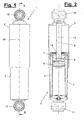
- FIG. 1 shows a shock absorber (1), which can be preferably used for vehicles, especially for heavy trucks.
- the shock absorber (1) is particularly suitable for trucks or their trailers, especially semi-trailers.
- the shock absorber (1) can be used here for stroke limitation and as a catching device in case of failure of the axle suspension.
- the shock absorber (1) is connected in a conventional manner by means of upper and lower connections (16,17) with the axle or the suspension and the chassis.
- the shock absorber (1) consists of two relative to each other in the direction of the longitudinal axis (15) movable and telescopically encompassing housing parts (2,3), of which one housing part (3) receives a working cylinder (4), in particular a hydraulic damping cylinder.
- a one- or multi-part piston assembly (6) with a piston rod (5) is arranged in the cylinder (4) in the cylinder (4) .
- the piston assembly (6) is movably guided in the cylinder (4) along the cylinder axis (15).
- the piston rod (5) is longitudinally movably guided in a piston rod guide (7) at the upper cylinder end and projects out of the cylinder (4) and the housing (3).
- the piston rod (5) is connected at the free end to the other housing part (2) or in the connection (16).
- the damping device may otherwise be of any and possibly conventional design.
- the shock absorber (1) has a stop (8) for the piston rod (5).
- This stop (8) can serve to limit the extension length of the piston rod (5).
- the stop (8) acts between the piston rod (5) and the piston rod guide (7) and is arranged spatially very close to the piston assembly (6). The stop area thus takes up very little space.
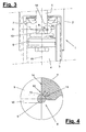
- the detailed design of the stop (8) is in FIGS. 3 to 5 shown.
- the stop (8) consists of a locking ring or stop ring (9) on the piston rod (5) and a stop shoulder (11) on the piston rod guide (7).
- the piston rod (5) thereby strikes against the stopper ring (9) on the piston rod guide (7).
- the stop ring (9) is fastened, for example, in a circumferential groove (10) of the piston rod (5).
- the stop ring (9) is in this case preferably designed as a spring ring and clipped into the groove (10). He is held here form-fitting and projects about half of its circumference outward on the piston rod circumference.
- the stop ring (9) preferably has a circular cross-section, but may otherwise have another, for example, oval or prismatic shape.
- the stop shoulder (11) is formed on the front of the piston rod guide (7) or mounted as an insert and is located in the extension direction, if necessary, at a distance in front of the guide surface (14) for the piston rod (5).
- the stop shoulder (11) preferably extends circumferentially annularly and concentrically around the cylinder axis (15) and has a substantially rounded shell shape, which is adapted to the outer shape of the stop ring (9). There are various possibilities for this shape adjustment.
- the stop shoulder (11) covers, e.g. less than a quarter of the outer circumference of the stop ring (9).
- the shoulder edges preferably merge with soft roundings in the adjacent surfaces of the piston rod guide (7).
- the shell shape of the stop shoulder (11) can according to FIG. 4 for a tailor-made system completely correspond to the outer shape of the stop ring (9).
- the shell shape may, for example, be circular in cross-section and have the same curvature as the outer circumference of the stop ring (9).
- the shell shape can also have a different shape, for example oval or prismatic.
- the shell shape of the stop shoulder (11) only partially correspond to the outer shape of the stop ring (9) and the guide surface (14) or the piston axis have a small extension (18) with a flatter curvature, so that the stop ring (9) as in FIG. 4 shown, initially only in a partial area (19) rests against the shell mold.
- the extension is designed, for example, for a deformation of the stop shoulder (11) with a high impact force, so that then the shoulder (9) with a larger contact surface optimally applied to the shell shape.
- annular deformation zone (12) with a likewise annular recess (13) is arranged on the piston rod guide (7).
- the recess (13) which is concentric with the cylinder axis (15) has a stepped shape with a substantially rectangular shape in cross-section.
- the recess (13) distances the stop shoulder (11) from the guide surface (14) in the axial and radial directions. The inner end of the stop shoulder (11) thereby does not extend to the outer periphery of the piston rod (5).
- FIG. 4 shows this with directional arrows. This serves the better support and also the relief of the guide surface (14).
- the stop shoulder (11) also deform in case of overload and thereby absorb the axial forces, without thereby the guide surface (14) is affected or even damaged.
- the degradation by controlled deformation of the piston rod guide (7) is possible without the piston rod guide (7) breaks.
- the forces occurring in the event of a failure of the axle suspension can be absorbed.
- stop ring (9) and the stop shoulder (11) need not necessarily have a circular or shell shape. It is also a prismatic shape possible, wherein in the contact area obliquely to the cylinder axis (15) aligned abutment surfaces on the ring (9) and on the stop shoulder (11) are provided to allow radial directional components of the load and force.
Landscapes
- Engineering & Computer Science (AREA)
- General Engineering & Computer Science (AREA)
- Mechanical Engineering (AREA)
- Fluid-Damping Devices (AREA)
- Vibration Dampers (AREA)
Description
- Die Erfindung betrifft einen Stoßdämpfer für Fahrzeuge, insbesondere Schwerlastfahrzeuge, mit den Merkmalen im Oberbegriff des Hauptanspruchs.
- Aus der
DE 83 01 051 U1 ist ein Zweirohrschwingungsdämpfer bekannt, der ein Behälterrohr besitzt, in dem ein Zylinder mit einer Kolbenstangenführung und einer hohlen Kolbenstange angeordnet ist, welche am Ende eine Aufweitung zur Aufnahme einer Dämpfeinrichtung aufweist. Auf der Kolbenstange ist außen am Umfang ein Anschlagring als Zuganschlag für den Schwingungsdämpfer angeordnet, der mit der Frontseite der Kolbenstangenführung zusammenwirkt und an diese anschlägt. - Ein anderer Stoßdämpfer ist aus der
DE 28 53 914 bekannt. Der im Stoßdämpfer enthaltene Arbeitszylinder hat einen Anschlag zur Begrenzung der Auszugbewegung der Kolbenstange. Dieser Anschlag wird von einer auf der Kolbenstange befestigten Anschlagscheibe und gebildet, die mittels eines an einer Umfangnut der Kolbenstange eingelassenen Ringes gehalten wird und die zur Auszugbegrenzung gegen die Kolbenstangenführung anschlägt. Aus der Praxis ist es außerdem bekannt, eine solche Anschlagscheibe an der Kolbenstange durch Schweißen oder auf andere Weise zu befestigen. Die vorbekannte Konstruktion ist bau- und platzaufwändig. Problematisch ist hierbei auch der an der Kolbenstangenführung auftretende Verschleiß. - Die
DE 78 11 060 U1 zeigt einen Stoßdämpfer mit einem an der Kolbenstange angeordneten ringförmigen Zuganschlag, der am Ende der Auszugbewegung an einem der Kolbenstangenführung vorgeschalteten Ring anschlägt. Dieser Ring ist mehrteilig und besteht aus einem elastischen Anschlagring aus Gummi, der rückseitig an der Kolbenstangenführung anliegt und aus einem steifen Ring. Die beiden Ringe berühren sich über kegelförmige Stirnflächen. Im Anschlagfall soll sich der in den Zylinder eingeformte elastische Anschlagring verformen und in einen Freiraum zur Kolbenstange hin ausdehnen. - Es ist Aufgabe der vorliegenden Erfindung, einen Stoßdämpfer mit einem besseren Anschlag aufzuzeigen.
- Die Erfindung löst diese Aufgabe mit den Merkmalen im Hauptanspruch.
- Der Anschlag wird von einer an der Kolbenstangenführung befindlichen Anschlagschulter gebildet, die direkt mit dem an der Kolbenstange angebrachten Anschlagring zusammenwirkt. Der Anschlagring übernimmt dadurch selbst Anschlagfunktion. Diese Bauweise spart erheblich Platz, insbesondere in der Baulänge des Stoßdämpfers. Zudem wird die Konstruktion vereinfacht und verbilligt. Auch der Bau- und Montageaufwand wird gemindert.
- Mittels einer zwischen der Anschlagschulter und der Führungsfläche angeordneten Deformationszone wird die Führungsfläche gegenüber Verformungen und Setzungserscheinungen geschützt. Insbesondere werden die im Dauerbetrieb unvermeidbaren Setzungen bzw. Verformungen, die der Anschlagring an der Kolbenstangenführung hinterlässt, absorbiert und von der Anschlagschulter aufgenommen. Durch diese Bauteilgeometrie wird der Kraftfluss in Anschlagstellung mit einer großen radialen Komponente übertragen und eine sonst. unvermeidbare "Einbettung" des Federrings durch die Deformationszone aufgefangen. Das erforderliche Bewegungsspiel zwischen Kolbenstange und Kolbenführung bleibt dadurch unbeeinträchtigt.
- Die Anschlaggestaltung ist vor allem für Stoßdämpfer von Fahrzeugen von Vorteil, kann aber auch in anderen Anwendungsbereichen eingesetzt werden. Besondere Vorteile ergeben sich bei Schwerlastfahrzeugen, z.B. Lastkraftwagen und deren Anhängern, insbesondere Sattelaufliegern. Dies gilt speziell für den Fall, dass die Stoßdämpfer auch als Hubbegrenzung und als Fangeinrichtung bei Lastkraftwagen oder Anhängern eingesetzt werden, um u. a. sicherzustellen, dass die Achse immer mit dem Fahrzeug verbunden bleibt. Der Stoßdämpfer und der beanspruchte Anschlag werden hierbei dynamisch und statisch stark belastet. Durch die Anschlagkonstruktion werden Brüche zuverlässig vermieden, wobei sich außerdem bei hoher statischer Last im Sinne der Fangeinrichtung Verformungen vor allem im Bereich der Deformationszone ergeben und dort unschädlich sind.
- In den Unteransprüchen sind weitere vorteilhafte Ausgestaltungen der Erfindung angegeben.
- Die Erfindung ist in den Zeichnungen beispielsweise und schematisch dargestellt. Im Einzelnen zeigen:
- Figur 1:
- Einen Stoßdämpfer in Seitenansicht,
- Figur 2:
- einen Längsschnitt durch den Stoßdämpfer von
Figur 1 , - Figur 3:
- eine abgebrochene und vergrößerte Darstellung des Anschlagbereichs der Kolbenstange von
Figur 2 , - Figur 4:
- eine weiter vergrößerte Detaildarstellung des Bereichs IV von
Figur 3 und - Figur 5:
- eine Variante zu
Figur 4 . -
Figur 1 zeigt einen Stoßdämpfer (1), der vorzugsweise für Fahrzeuge, insbesondere für Schwerlastfahrzeuge eingesetzt werden kann. Der Stoßdämpfer (1) eignet sich besonders für Lastkraftwagen oder deren Anhänger, insbesondere Sattelauflieger. Der Stoßdämpfer (1) kann hierbei zur Hubbegrenzung und auch als Fangeinrichtung beim Versagen der Achsaufhängung benutzt werden. - Der Stoßdämpfer (1) wird in üblicher Weise mittels oberer und unterer Anschlüsse (16,17) mit der Achse bzw. der Radaufhängung und dem Fahrgestell verbunden. Der Stoßdämpfer (1) besteht aus zwei relativ zueinander in Richtung der Längsachse (15) beweglichen und einander teleskopartig umgreifenden Gehäuseteilen (2,3), von denen das eine Gehäuseteil (3) einen Arbeitszylinder (4), insbesondere einen hydraulischen Dämpfzylinder aufnimmt.
- Im Zylinder (4) ist eine ein- oder mehrteilige Kolbenanordnung (6) mit einer Kolbenstange (5) angeordnet. Die Kolbenanordnung (6) ist im Zylinder (4) längs der Zylinderachse (15) beweglich geführt. Die Kolbenstange (5) ist in einer Kolbenstangenführung (7) am oberen Zylinderende längsbeweglich geführt und ragt hier aus dem Zylinder (4) und dem Gehäuse (3) heraus. Die Kolbenstange (5) ist am freien Ende mit dem anderen Gehäuseteil (2) bzw. im Anschluss (16) verbunden. Die Dämpfeinrichtung kann ansonsten von beliebiger und ggf. konventioneller Bauart sein.
- Der Stoßdämpfer (1) besitzt einen Anschlag (8) für die Kolbenstange (5). Dieser Anschlag (8) kann zur Begrenzung der Ausziehlänge der Kolbenstange (5) dienen. Der Anschlag (8) wirkt zwischen der Kolbenstange (5) und der Kolbenstangenführung (7) und ist dabei räumlich sehr nahe an der Kolbenanordnung (6) angeordnet. Der Anschlagbereich braucht dadurch nur sehr wenig Platz.
- Die Detailgestaltung des Anschlags (8) ist in
Figur 3 bis 5 dargestellt. Der Anschlag (8) besteht aus einem Sperrring oder Anschlagring (9) an der Kolbenstange (5) und einer Anschlagschulter (11) an der Kolbenstangenführung (7). Die Kolbenstange (5) schlägt dadurch mit dem Anschlagring (9) an der Kolbenstangenführung (7) an. - Der Anschlagring (9) ist z.B. in einer umfangseitigen Nut (10) der Kolbenstange (5) befestigt. Der Anschlagring (9) ist hierbei vorzugsweise als Federring ausgeführt und in die Nut (10) eingeclipst. Er wird hier formschlüssig gehalten und ragt etwa mit der Hälfte seines Umfangs nach außen über den Kolbenstangenumfang vor. Der Anschlagring (9) hat vorzugsweise einen kreisrunden Querschnitt, kann ansonsten aber auch eine andere, z.B. ovale oder prismatische Formgebung besitzen.
- Die Anschlagschulter (11) ist an der Vorderseite der Kolbenstangenführung (7) angeformt oder als Einsatzteil angebaut und befindet sich in Auszugsrichtung ggf. mit Abstand vor der Führungsfläche (14) für die Kolbenstange (5). Die Anschlagschulter (11) erstreckt sich vorzugsweise umlaufend ringförmig und konzentrisch um die Zylinderachse (15) und besitzt eine im wesentlichen gerundete Schalenform, die an die Außenform des Anschlagringes (9) angepasst ist. Für diese Formanpassung gibt es verschiedene Möglichkeiten.
- Die Anschlagschulter (11) bedeckt dabei z.B. weniger als ein Viertel des Außenumfangs des Anschlagringes (9). Die Schulterränder gehen vorzugsweise mit weichen Abrundungen in die angrenzenden Flächen der Kolbenstangenführung (7) über.
- Die Schalenform der Anschlagschulter (11) kann gemäß
Figur 4 für eine passgenaue Anlage vollständig der Außenform des Anschlagrings (9) entsprechen. Die Schalenform kann z.B. im Querschnitt kreisrund sein und die gleiche Krümmung wie der Außenumfang des Anschlagrings (9) haben. Entsprechend den vorgenannten Varianten der Ringform kann auch die Schalenform eine andere, z.B. ovale oder prismatische Formgebung besitzen. - Alternativ kann gemäß
Figur 5 die Schalenform der Anschlagschulter (11) nur bereichsweise der Außenform des Anschlagrings (9) entsprechen und zur Führungsfläche (14) bzw. zur Kolbenachse hin eine kleine Erweiterung (18) mit einer flacheren Krümmung haben, so dass der Anschlagring (9) wie inFigur 4 dargestellt, zunächst nur in einem Teilbereich (19) an der Schalenform anliegt. Die Erweiterung ist z.B. auf eine Verformung der Anschlagschulter (11) bei hoher Anschlagkraft ausgelegt, so dass dann bei Schulterverformung der Anschlagring (9) mit einer größeren Kontaktfläche optimal an der Schalenform anliegt. - Zwischen der Anschlagschulter (11) und der Führungsfläche (14) für die Kolbenstange (5) ist an der Kolbenstangenführung (7) eine ringförmige Deformationszone (12) mit einer ebenfalls ringförmigen Ausnehmung (13) angeordnet. Die zur Zylinderachse (15) konzentrische Ausnehmung (13) besitzt im Querschnitt eine Stufenform mit einer im Wesentlichen rechteckigen Gestalt. Die Ausnehmung (13) distanziert die Anschlagschulter (11) von der Führungsfläche (14) in axialer und radialer Richtung. Das innere Ende der Anschlagschulter (11) reicht dadurch nicht bis zum Außenumfang der Kolbenstange (5).
- Durch diese Gestaltung des Anschlags (8) werden im Belastungs- und Anschlagfall die auftretenden Kräfte mit einer deutlichen radialen Komponente in die Kolbenstangenführung (7) eingeleitet.
Figur 4 zeigt dies mit Richtungspfeilen. Dies dient der besseren Abstützung und auch der Entlastung der Führungsfläche (14). Durch die Ausnehmung (13) kann die Anschlagschulter (11) sich außerdem im Überlastfall verformen und dabei auch die axialen Kräfte aufnehmen, ohne dass hierdurch die Führungsfläche (14) in Mitleidenschaft gezogen oder gar beschädigt wird. Im Überlastfall ist dadurch auch der Abbau durch kontrollierte Verformung der Kolbenstangenführung (7) möglich, ohne das die Kolbenstangenführung (7) bricht. Hierbei können insbesondere die bei einem Versagen der Achsaufhängung auftretenden Kräfte aufgenommen werden. - Abwandlungen der gezeigten Ausführungsformen sind in verschiedener Weise möglich. Dies betrifft einerseits die Gestaltung der Stoßdämpferbauteile, aber auch den Anschlag selbst. Statt des in einer Nut eingelegten Anschlagrings mit kreisrundem Querschnitt kann auch ein Anschlagring mit halbkreisförmigen Querschnitt auf dem Außenumfang der Kolbenstange (5) in geeigneter Weise, z.B. durch Schweißen oder dergleichen, befestigt sein.
- Ferner müssen der Anschlagring (9) und die Anschlagschulter (11) nicht zwangsweise eine Kreis- oder Schalenform haben. Es ist auch eine prismatische Formgebung möglich, wobei im Anlagebereich schräg zur Zylinderachse (15) ausgerichtete Anschlagflächen am Ring (9) und an der Anschlagschulter (11) vorhanden sind, um radiale Richtungskomponenten der Belastung und Kraftaufnahme zu ermöglichen.
-
- 1
- Stoßdämpfer
- 2
- Gehäuseteil
- 3
- Gehäuseteil
- 4
- Zylinder
- 5
- Kolbenstange
- 6
- Kolbenanordnung, Kolben
- 7
- Kolbenstangenführung
- 8
- Anschlag
- 9
- Anschlagring, Federring
- 10
- Nut in Kolbenstange
- 11
- Anschlagschulter
- 12
- Deformationszone
- 13
- Ausnehmung
- 14
- Führungsfläche
- 15
- Zylinderachse
- 16
- Anschluss oben
- 17
- Anschluss unten
- 18
- Erweiterung
- 19
- Teilbereich
Claims (12)
- Stoßdämpfer für Fahrzeuge, insbesondere Schwerlastfahrzeuge, mit einem Zylinder (4), einer Kolbenanordnung (6), einer Kolbenstange (5), einer Kolbenstangenführung (7) und einem Anschlag (8) zur Begrenzung der Ausziehbewegung der Kolbenstange (5), wobei der Anschlag (8) einen auf der Kolbenstange (5) befindlichen Anschlagring (9) aufweist, der an der Kolbenstangenführung (7) anschlägt, dadurch gekennzeichnet, dass der Anschlag (8) eine Anschlagschulter (11) an der Kolbenstangenführung (7) aufweist, die mit dem Anschlagring (9) zusammenwirkt, wobei die Kolbenstangenführung (7) zwischen der Anschlagschulter (11) und einer Führungsfläche (14) für die Kolbenstange (5) eine ringförmige Deformationszone (12) mit einer Ausnehmung (13) aufweist, welche im Überlastfall eine Verformung der Anschlagschulter (11) unter Aufnahme axialer Kräfte ermöglicht.
- Stoßdämpfer nach Anspruch 1, dadurch gekennzeichnet, dass die Anschlagschulter (11) eine an die Außenform des Anschlagrings (9) angepasste Schalenform aufweist.
- Stoßdämpfer nach Anspruch 1 oder 2, dadurch gekennzeichnet, dass die Schalenform der Anschlagschulter (11) der Außenform des Anschlagrings (9) entspricht.
- Stoßdämpfer nach Anspruch 1 oder 2, dadurch gekennzeichnet, dass die Schalenform der Anschlagschulter (11) der Außenform des Anschlagrings (9) bereichsweise (19) entspricht, wobei die Schalenform zur Kolbenachse hin eine kleine Erweiterung (18) mit einer flacheren Krümmung aufweist.
- Stoßdämpfer nach einem der vorhergehenden Ansprüche, dadurch gekennzeichnet, dass die Anschlagschulter (11) eine gerundete Schalenform und der Anschlagring (9) eine gerundete Außenform aufweisen.
- Stoßdämpfer nach einem der vorhergehenden Ansprüche, dadurch gekennzeichnet, dass die Schalenform der Anschlagschulter (11) weniger als 1/4 des Umfangs des Anschlagrings (9) bedeckt.
- Stoßdämpfer nach einem der vorhergehenden Ansprüche, dadurch gekennzeichnet, dass der Anschlagring (9) einen kreisförmigen oder halbkreisförmigen Querschnitt aufweist.
- Stoßdämpfer nach einem der vorhergehenden Ansprüche, dadurch gekennzeichnet, dass die ringförmige Ausnehmung (13) unmittelbar vor der Führungsfläche (14) angeordnet ist.
- Stoßdämpfer nach einem der vorhergehenden Ansprüche, dadurch gekennzeichnet, dass die Ausnehmung (13) im Querschnitt eine Stufenform aufweist.
- Stoßdämpfer nach einem der vorhergehenden Ansprüche, dadurch gekennzeichnet, dass die Ausnehmung (13) die Anschlagschulter (11) von der Führungsfläche (14) axial und radial distanziert.
- Stoßdämpfer nach einem der vorhergehenden Ansprüche, dadurch gekennzeichnet, dass der Anschlagring (9) als Federring ausgebildet ist.
- Stoßdämpfer nach einem der vorhergehenden Ansprüche, dadurch gekennzeichnet, dass der Anschlagring (9) in einer umfangseitigen Nut (10) der Kolbenstange (5) angeordnet ist.
Applications Claiming Priority (2)
| Application Number | Priority Date | Filing Date | Title |
|---|---|---|---|
| DE20319511U DE20319511U1 (de) | 2003-12-16 | 2003-12-16 | Stoßdämpfer mit Anschlag |
| DE20319511U | 2003-12-16 |
Publications (2)
| Publication Number | Publication Date |
|---|---|
| EP1544499A1 EP1544499A1 (de) | 2005-06-22 |
| EP1544499B1 true EP1544499B1 (de) | 2009-09-16 |
Family
ID=34485644
Family Applications (1)
| Application Number | Title | Priority Date | Filing Date |
|---|---|---|---|
| EP04029135A Expired - Lifetime EP1544499B1 (de) | 2003-12-16 | 2004-12-09 | Stossdämpfer mit Anschlag |
Country Status (3)
| Country | Link |
|---|---|
| EP (1) | EP1544499B1 (de) |
| AT (1) | ATE443218T1 (de) |
| DE (2) | DE20319511U1 (de) |
Cited By (2)
| Publication number | Priority date | Publication date | Assignee | Title |
|---|---|---|---|---|
| DE102014206840A1 (de) | 2014-04-09 | 2015-10-15 | Zf Friedrichshafen Ag | Endanschlaganordnung eines Schwingungsdämpfers für Kraftfahrzeuge |
| DE102015210078A1 (de) | 2015-06-01 | 2016-12-01 | Thyssenkrupp Ag | Schwingungsdämpfer mit Zuganschlag |
Families Citing this family (1)
| Publication number | Priority date | Publication date | Assignee | Title |
|---|---|---|---|---|
| DE102008028699B3 (de) * | 2008-06-17 | 2010-01-07 | Zf Friedrichshafen Ag | Schwingungsdämpfer, insbesondere für Kraftfahrzeuge |
Family Cites Families (12)
| Publication number | Priority date | Publication date | Assignee | Title |
|---|---|---|---|---|
| JPS5530501A (en) * | 1978-08-21 | 1980-03-04 | Kayaba Ind Co Ltd | Stay damper |
| DE2851366A1 (de) * | 1978-11-28 | 1980-06-12 | Stabilus Gmbh | Gasfeder mit festgehaltener kolbenstange in eingefahrener stellung |
| DE2853914A1 (de) * | 1978-12-14 | 1980-07-03 | Fichtel & Sachs Ag | Schwingungsdaempfer oder federbein mit einem hydraulisch-mechanischen zuganschlag |
| DE8301051U1 (de) * | 1983-01-17 | 1983-06-30 | Fichtel & Sachs Ag, 8720 Schweinfurt, De | |
| DE9404863U1 (de) * | 1994-03-22 | 1994-05-26 | Fella-Werke Gmbh, 90537 Feucht | Druckmittelbeaufschlagtes Stellglied mit Endlagenverriegelung |
| GB2336646A (en) * | 1998-02-13 | 1999-10-27 | Tenneco Automotive Inc | Monostrut having a "burp" valve |
| DE19817512A1 (de) * | 1998-04-20 | 1999-08-05 | Weichhart Fahrzeugteile Gmbh | KFZ-Stoßdämpfer mit verstellbaren Kolbenstangen-Endanschlag |
| DE19823024C2 (de) * | 1998-05-22 | 2001-11-15 | Krupp Bilstein Gmbh | Hydraulischer Schwingungsdämpfer und Verfahren zum Zusammenbau eines derartigen Schwingungsdämpfers |
| DE19944758C1 (de) * | 1999-09-17 | 2001-04-19 | Gosow Fahrzeugtechnik Gmbh | Aushubbegrenzung für Stoßdämpfer |
| JP2001153171A (ja) * | 1999-11-25 | 2001-06-08 | Showa Corp | 中空ロッドのリバウンドシート固定方法 |
| SE0103380D0 (sv) * | 2001-10-10 | 2001-10-10 | Hydrotech Construction Co Ab | Självverkande låscylinder och anordning för indikering av låscylinderns tillstånd |
| DE10228223A1 (de) * | 2002-06-25 | 2004-01-22 | Zf Sachs Ag | Anschlagring für ein Kolben-Zylinderaggregat |
-
2003
- 2003-12-16 DE DE20319511U patent/DE20319511U1/de not_active Expired - Lifetime
-
2004
- 2004-12-09 DE DE502004010064T patent/DE502004010064D1/de not_active Expired - Lifetime
- 2004-12-09 AT AT04029135T patent/ATE443218T1/de not_active IP Right Cessation
- 2004-12-09 EP EP04029135A patent/EP1544499B1/de not_active Expired - Lifetime
Cited By (4)
| Publication number | Priority date | Publication date | Assignee | Title |
|---|---|---|---|---|
| DE102014206840A1 (de) | 2014-04-09 | 2015-10-15 | Zf Friedrichshafen Ag | Endanschlaganordnung eines Schwingungsdämpfers für Kraftfahrzeuge |
| DE102014206840B4 (de) * | 2014-04-09 | 2016-09-08 | Zf Friedrichshafen Ag | Endanschlaganordnung eines Schwingungsdämpfers für Kraftfahrzeuge |
| DE102015210078A1 (de) | 2015-06-01 | 2016-12-01 | Thyssenkrupp Ag | Schwingungsdämpfer mit Zuganschlag |
| WO2016193211A1 (de) | 2015-06-01 | 2016-12-08 | Thyssenkrupp Bilstein Gmbh | Schwingungsdämpfer mit zuganschlag |
Also Published As
| Publication number | Publication date |
|---|---|
| DE502004010064D1 (de) | 2009-10-29 |
| ATE443218T1 (de) | 2009-10-15 |
| EP1544499A1 (de) | 2005-06-22 |
| DE20319511U1 (de) | 2005-04-28 |
Similar Documents
| Publication | Publication Date | Title |
|---|---|---|
| DE19923847B4 (de) | Federbeinaufhängung für Fahrzeuge | |
| EP2671001B1 (de) | Hydropneumatische kolbenzylinderanordnung | |
| DE102015007743B4 (de) | Schublager und druckluftbeaufschlagter Stoßdämpfer | |
| EP3510303B1 (de) | Luftfedereinheit mit geteilter aussenführung | |
| EP2414180B1 (de) | Elastomergelenk | |
| EP2605923B1 (de) | Luftfederbein mit elastischer kolbenlagerung | |
| DE112009002533T5 (de) | Fahrzeugradscheibe | |
| DE2726676A1 (de) | Federelement, insbesondere zur elastischen lagerung von antriebs- oder sonstigen aggregaten in kraftfahrzeugen | |
| EP1693233B1 (de) | Luftfederbein mit zentrisch angeordnetem Dämpfer | |
| DE102006037034B4 (de) | Luftfeder für ein Fahrzeug | |
| WO2012069161A1 (de) | Dämpfer für ein kraftfahrzeug | |
| DE112015005299B4 (de) | Stossdämpfer, die eine basisanordnung aus verbundstoff mit einem angeformten verschlusseinsatz aufweisen | |
| DE3204816A1 (de) | Oberes verankerungssystem fuer ein federbein einer mcpherson-aufhaengung | |
| DE102004007960B4 (de) | Kolben-Zylinder-Aggregat | |
| DE1780074A1 (de) | Radaufhaengung fuer Kraftfahrzeuge | |
| EP1820674B1 (de) | Einstellbares Federbein für Kraftfahrzeuge | |
| DE102006014331B4 (de) | Doppelohr-Hydraulikstossdämpfer | |
| DE19521128C1 (de) | Stützlager für einen Stoßdämpfer eines Kraftfahrzeuges | |
| DE10329069B4 (de) | Vibrationsisolierende Buchse | |
| DE20319511U1 (de) | Stoßdämpfer mit Anschlag | |
| EP1923301B1 (de) | Schwingungsdämpfer mit Endanschlag | |
| EP2708387B1 (de) | Lager | |
| DE102018101521B4 (de) | Verdrehsicherung | |
| EP1979646B1 (de) | Luftfeder- und dämpfereinheit mit zuganschlag | |
| DE2932515A1 (de) | Anordnung zur befestigung eines hydraulischen schwingungsdaempfers o.dgl. im tragrohr eines radfuehrenden federbeins |
Legal Events
| Date | Code | Title | Description |
|---|---|---|---|
| PUAI | Public reference made under article 153(3) epc to a published international application that has entered the european phase |
Free format text: ORIGINAL CODE: 0009012 |
|
| AK | Designated contracting states |
Kind code of ref document: A1 Designated state(s): AT BE BG CH CY CZ DE DK EE ES FI FR GB GR HU IE IS IT LI LT LU MC NL PL PT RO SE SI SK TR |
|
| AX | Request for extension of the european patent |
Extension state: AL BA HR LV MK YU |
|
| RIN1 | Information on inventor provided before grant (corrected) |
Inventor name: FRIESS, GERHARD |
|
| 17P | Request for examination filed |
Effective date: 20050907 |
|
| AKX | Designation fees paid |
Designated state(s): AT BE BG CH CY CZ DE DK EE ES FI FR GB GR HU IE IS IT LI LT LU MC NL PL PT RO SE SI SK TR |
|
| GRAP | Despatch of communication of intention to grant a patent |
Free format text: ORIGINAL CODE: EPIDOSNIGR1 |
|
| GRAS | Grant fee paid |
Free format text: ORIGINAL CODE: EPIDOSNIGR3 |
|
| GRAA | (expected) grant |
Free format text: ORIGINAL CODE: 0009210 |
|
| AK | Designated contracting states |
Kind code of ref document: B1 Designated state(s): AT BE BG CH CY CZ DE DK EE ES FI FR GB GR HU IE IS IT LI LT LU MC NL PL PT RO SE SI SK TR |
|
| REG | Reference to a national code |
Ref country code: GB Ref legal event code: FG4D Free format text: NOT ENGLISH |
|
| REG | Reference to a national code |
Ref country code: CH Ref legal event code: EP |
|
| REG | Reference to a national code |
Ref country code: IE Ref legal event code: FG4D |
|
| REF | Corresponds to: |
Ref document number: 502004010064 Country of ref document: DE Date of ref document: 20091029 Kind code of ref document: P |
|
| PG25 | Lapsed in a contracting state [announced via postgrant information from national office to epo] |
Ref country code: SE Free format text: LAPSE BECAUSE OF FAILURE TO SUBMIT A TRANSLATION OF THE DESCRIPTION OR TO PAY THE FEE WITHIN THE PRESCRIBED TIME-LIMIT Effective date: 20090916 Ref country code: LT Free format text: LAPSE BECAUSE OF FAILURE TO SUBMIT A TRANSLATION OF THE DESCRIPTION OR TO PAY THE FEE WITHIN THE PRESCRIBED TIME-LIMIT Effective date: 20090916 Ref country code: FI Free format text: LAPSE BECAUSE OF FAILURE TO SUBMIT A TRANSLATION OF THE DESCRIPTION OR TO PAY THE FEE WITHIN THE PRESCRIBED TIME-LIMIT Effective date: 20090916 |
|
| LTIE | Lt: invalidation of european patent or patent extension |
Effective date: 20090916 |
|
| PG25 | Lapsed in a contracting state [announced via postgrant information from national office to epo] |
Ref country code: SI Free format text: LAPSE BECAUSE OF FAILURE TO SUBMIT A TRANSLATION OF THE DESCRIPTION OR TO PAY THE FEE WITHIN THE PRESCRIBED TIME-LIMIT Effective date: 20090916 Ref country code: PL Free format text: LAPSE BECAUSE OF FAILURE TO SUBMIT A TRANSLATION OF THE DESCRIPTION OR TO PAY THE FEE WITHIN THE PRESCRIBED TIME-LIMIT Effective date: 20090916 |
|
| PG25 | Lapsed in a contracting state [announced via postgrant information from national office to epo] |
Ref country code: CY Free format text: LAPSE BECAUSE OF FAILURE TO SUBMIT A TRANSLATION OF THE DESCRIPTION OR TO PAY THE FEE WITHIN THE PRESCRIBED TIME-LIMIT Effective date: 20090916 |
|
| REG | Reference to a national code |
Ref country code: IE Ref legal event code: FD4D |
|
| PG25 | Lapsed in a contracting state [announced via postgrant information from national office to epo] |
Ref country code: IS Free format text: LAPSE BECAUSE OF FAILURE TO SUBMIT A TRANSLATION OF THE DESCRIPTION OR TO PAY THE FEE WITHIN THE PRESCRIBED TIME-LIMIT Effective date: 20100116 Ref country code: EE Free format text: LAPSE BECAUSE OF FAILURE TO SUBMIT A TRANSLATION OF THE DESCRIPTION OR TO PAY THE FEE WITHIN THE PRESCRIBED TIME-LIMIT Effective date: 20090916 Ref country code: ES Free format text: LAPSE BECAUSE OF FAILURE TO SUBMIT A TRANSLATION OF THE DESCRIPTION OR TO PAY THE FEE WITHIN THE PRESCRIBED TIME-LIMIT Effective date: 20091227 Ref country code: RO Free format text: LAPSE BECAUSE OF FAILURE TO SUBMIT A TRANSLATION OF THE DESCRIPTION OR TO PAY THE FEE WITHIN THE PRESCRIBED TIME-LIMIT Effective date: 20090916 Ref country code: IE Free format text: LAPSE BECAUSE OF FAILURE TO SUBMIT A TRANSLATION OF THE DESCRIPTION OR TO PAY THE FEE WITHIN THE PRESCRIBED TIME-LIMIT Effective date: 20090916 Ref country code: PT Free format text: LAPSE BECAUSE OF FAILURE TO SUBMIT A TRANSLATION OF THE DESCRIPTION OR TO PAY THE FEE WITHIN THE PRESCRIBED TIME-LIMIT Effective date: 20100118 |
|
| PG25 | Lapsed in a contracting state [announced via postgrant information from national office to epo] |
Ref country code: SK Free format text: LAPSE BECAUSE OF FAILURE TO SUBMIT A TRANSLATION OF THE DESCRIPTION OR TO PAY THE FEE WITHIN THE PRESCRIBED TIME-LIMIT Effective date: 20090916 |
|
| BERE | Be: lapsed |
Owner name: AL-KO KOBER A.G. Effective date: 20091231 |
|
| PLBE | No opposition filed within time limit |
Free format text: ORIGINAL CODE: 0009261 |
|
| STAA | Information on the status of an ep patent application or granted ep patent |
Free format text: STATUS: NO OPPOSITION FILED WITHIN TIME LIMIT |
|
| PG25 | Lapsed in a contracting state [announced via postgrant information from national office to epo] |
Ref country code: DK Free format text: LAPSE BECAUSE OF FAILURE TO SUBMIT A TRANSLATION OF THE DESCRIPTION OR TO PAY THE FEE WITHIN THE PRESCRIBED TIME-LIMIT Effective date: 20090916 Ref country code: MC Free format text: LAPSE BECAUSE OF NON-PAYMENT OF DUE FEES Effective date: 20100701 |
|
| REG | Reference to a national code |
Ref country code: CH Ref legal event code: PL |
|
| 26N | No opposition filed |
Effective date: 20100617 |
|
| REG | Reference to a national code |
Ref country code: FR Ref legal event code: ST Effective date: 20100831 |
|
| PG25 | Lapsed in a contracting state [announced via postgrant information from national office to epo] |
Ref country code: GR Free format text: LAPSE BECAUSE OF FAILURE TO SUBMIT A TRANSLATION OF THE DESCRIPTION OR TO PAY THE FEE WITHIN THE PRESCRIBED TIME-LIMIT Effective date: 20091217 Ref country code: BE Free format text: LAPSE BECAUSE OF NON-PAYMENT OF DUE FEES Effective date: 20091231 Ref country code: CH Free format text: LAPSE BECAUSE OF NON-PAYMENT OF DUE FEES Effective date: 20091231 Ref country code: FR Free format text: LAPSE BECAUSE OF NON-PAYMENT OF DUE FEES Effective date: 20091231 Ref country code: LI Free format text: LAPSE BECAUSE OF NON-PAYMENT OF DUE FEES Effective date: 20091231 |
|
| PG25 | Lapsed in a contracting state [announced via postgrant information from national office to epo] |
Ref country code: IT Free format text: LAPSE BECAUSE OF FAILURE TO SUBMIT A TRANSLATION OF THE DESCRIPTION OR TO PAY THE FEE WITHIN THE PRESCRIBED TIME-LIMIT Effective date: 20090916 Ref country code: BG Free format text: LAPSE BECAUSE OF FAILURE TO SUBMIT A TRANSLATION OF THE DESCRIPTION OR TO PAY THE FEE WITHIN THE PRESCRIBED TIME-LIMIT Effective date: 20091231 |
|
| PG25 | Lapsed in a contracting state [announced via postgrant information from national office to epo] |
Ref country code: LU Free format text: LAPSE BECAUSE OF NON-PAYMENT OF DUE FEES Effective date: 20091209 |
|
| PG25 | Lapsed in a contracting state [announced via postgrant information from national office to epo] |
Ref country code: AT Free format text: LAPSE BECAUSE OF NON-PAYMENT OF DUE FEES Effective date: 20091209 |
|
| PG25 | Lapsed in a contracting state [announced via postgrant information from national office to epo] |
Ref country code: HU Free format text: LAPSE BECAUSE OF FAILURE TO SUBMIT A TRANSLATION OF THE DESCRIPTION OR TO PAY THE FEE WITHIN THE PRESCRIBED TIME-LIMIT Effective date: 20100317 |
|
| PG25 | Lapsed in a contracting state [announced via postgrant information from national office to epo] |
Ref country code: TR Free format text: LAPSE BECAUSE OF FAILURE TO SUBMIT A TRANSLATION OF THE DESCRIPTION OR TO PAY THE FEE WITHIN THE PRESCRIBED TIME-LIMIT Effective date: 20090916 |
|
| PGFP | Annual fee paid to national office [announced via postgrant information from national office to epo] |
Ref country code: GB Payment date: 20131204 Year of fee payment: 10 |
|
| GBPC | Gb: european patent ceased through non-payment of renewal fee |
Effective date: 20141209 |
|
| REG | Reference to a national code |
Ref country code: DE Ref legal event code: R082 Ref document number: 502004010064 Country of ref document: DE Representative=s name: ERNICKE & ERNICKE, DE Ref country code: DE Ref legal event code: R081 Ref document number: 502004010064 Country of ref document: DE Owner name: AL-KO RECORD, S. A., ES Free format text: FORMER OWNER: AL-KO KOBER AG, 89359 KOETZ, DE Ref country code: DE Ref legal event code: R082 Ref document number: 502004010064 Country of ref document: DE Representative=s name: ERNICKE PATENT- UND RECHTSANWAELTE, DE |
|
| PG25 | Lapsed in a contracting state [announced via postgrant information from national office to epo] |
Ref country code: GB Free format text: LAPSE BECAUSE OF NON-PAYMENT OF DUE FEES Effective date: 20141209 |
|
| REG | Reference to a national code |
Ref country code: NL Ref legal event code: PD Owner name: AL-KO RECORD, S.A.; ES Free format text: DETAILS ASSIGNMENT: VERANDERING VAN EIGENAAR(S), OVERDRACHT; FORMER OWNER NAME: AL-KO KOBER SE Effective date: 20151106 Ref country code: NL Ref legal event code: HC Owner name: AL-KO KOBER SE; DE Free format text: DETAILS ASSIGNMENT: VERANDERING VAN EIGENAAR(S), VERANDERING VAN NAAM VAN DE EIGENAAR(S); FORMER OWNER NAME: AL-KO KOBER AG Effective date: 20151106 |
|
| PGFP | Annual fee paid to national office [announced via postgrant information from national office to epo] |
Ref country code: NL Payment date: 20231218 Year of fee payment: 20 Ref country code: DE Payment date: 20231214 Year of fee payment: 20 Ref country code: CZ Payment date: 20231130 Year of fee payment: 20 |
|
| REG | Reference to a national code |
Ref country code: DE Ref legal event code: R071 Ref document number: 502004010064 Country of ref document: DE |
|
| REG | Reference to a national code |
Ref country code: NL Ref legal event code: MK Effective date: 20241208 |
|
| PG25 | Lapsed in a contracting state [announced via postgrant information from national office to epo] |
Ref country code: CZ Free format text: LAPSE BECAUSE OF EXPIRATION OF PROTECTION Effective date: 20241209 |
|
| PG25 | Lapsed in a contracting state [announced via postgrant information from national office to epo] |
Ref country code: CZ Free format text: LAPSE BECAUSE OF EXPIRATION OF PROTECTION Effective date: 20241209 |