EP1544453A2 - Vanne ventilée pour vidange d'eau - Google Patents
Vanne ventilée pour vidange d'eau Download PDFInfo
- Publication number
- EP1544453A2 EP1544453A2 EP04106347A EP04106347A EP1544453A2 EP 1544453 A2 EP1544453 A2 EP 1544453A2 EP 04106347 A EP04106347 A EP 04106347A EP 04106347 A EP04106347 A EP 04106347A EP 1544453 A2 EP1544453 A2 EP 1544453A2
- Authority
- EP
- European Patent Office
- Prior art keywords
- housing
- bore
- drain opening
- cylinder pin
- cylindrical bore
- Prior art date
- Legal status (The legal status is an assumption and is not a legal conclusion. Google has not performed a legal analysis and makes no representation as to the accuracy of the status listed.)
- Granted
Links
- XLYOFNOQVPJJNP-UHFFFAOYSA-N water Substances O XLYOFNOQVPJJNP-UHFFFAOYSA-N 0.000 title claims abstract description 27
- 238000007789 sealing Methods 0.000 claims abstract description 23
- 239000000446 fuel Substances 0.000 claims abstract description 18
- 238000000034 method Methods 0.000 claims abstract description 6
- 238000007599 discharging Methods 0.000 claims description 6
- 238000006073 displacement reaction Methods 0.000 claims 1
- 239000003570 air Substances 0.000 description 8
- 238000009423 ventilation Methods 0.000 description 5
- 239000007788 liquid Substances 0.000 description 4
- 239000012080 ambient air Substances 0.000 description 3
- 230000007613 environmental effect Effects 0.000 description 3
- 238000009434 installation Methods 0.000 description 3
- 238000012423 maintenance Methods 0.000 description 3
- 238000002485 combustion reaction Methods 0.000 description 2
- 150000001875 compounds Chemical class 0.000 description 2
- 229910052751 metal Inorganic materials 0.000 description 2
- 239000002184 metal Substances 0.000 description 2
- 238000000465 moulding Methods 0.000 description 2
- 239000004033 plastic Substances 0.000 description 2
- 239000004952 Polyamide Substances 0.000 description 1
- 229910052782 aluminium Inorganic materials 0.000 description 1
- XAGFODPZIPBFFR-UHFFFAOYSA-N aluminium Chemical compound [Al] XAGFODPZIPBFFR-UHFFFAOYSA-N 0.000 description 1
- 238000011109 contamination Methods 0.000 description 1
- 239000000428 dust Substances 0.000 description 1
- 230000000694 effects Effects 0.000 description 1
- 238000001746 injection moulding Methods 0.000 description 1
- 230000010354 integration Effects 0.000 description 1
- 238000004519 manufacturing process Methods 0.000 description 1
- 239000002245 particle Substances 0.000 description 1
- 229920002647 polyamide Polymers 0.000 description 1
- 238000000926 separation method Methods 0.000 description 1
Images

Classifications
-
- B—PERFORMING OPERATIONS; TRANSPORTING
- B01—PHYSICAL OR CHEMICAL PROCESSES OR APPARATUS IN GENERAL
- B01D—SEPARATION
- B01D36/00—Filter circuits or combinations of filters with other separating devices
- B01D36/003—Filters in combination with devices for the removal of liquids
- B01D36/006—Purge means
-
- F—MECHANICAL ENGINEERING; LIGHTING; HEATING; WEAPONS; BLASTING
- F02—COMBUSTION ENGINES; HOT-GAS OR COMBUSTION-PRODUCT ENGINE PLANTS
- F02M—SUPPLYING COMBUSTION ENGINES IN GENERAL WITH COMBUSTIBLE MIXTURES OR CONSTITUENTS THEREOF
- F02M37/00—Apparatus or systems for feeding liquid fuel from storage containers to carburettors or fuel-injection apparatus; Arrangements for purifying liquid fuel specially adapted for, or arranged on, internal-combustion engines
- F02M37/22—Arrangements for purifying liquid fuel specially adapted for, or arranged on, internal-combustion engines, e.g. arrangements in the feeding system
- F02M37/24—Arrangements for purifying liquid fuel specially adapted for, or arranged on, internal-combustion engines, e.g. arrangements in the feeding system characterised by water separating means
Definitions
- the invention relates to a valve arrangement for discharging water from the housing a fuel filter.
- a valve arrangement for discharging water from the housing a fuel filter.
- the fuel filter used As a container in the fuel system, which allows the separation of water is usually the fuel filter used. For simplicity's sake, it will be at the bottom arranged a screw of the fuel filter, which closes an opening. By opening this screw, the water is drained during maintenance. Problematic In this design, the water can only drain if at the same time Air enters the system again. This is complicated by the fact that it is in the Fuel system is usually a closed system, with the result that that in the arrangement of only one drain screw at the same time water from the drain opening drain and air must flow into the drain opening. As a consequence, that the water often runs out unevenly or that the drainage opening by a possible contamination is narrowed and thus no more water can flow out.
- the object of the present invention is to provide a valve assembly in a To provide fuel filter, which ensures the smooth drainage of water through simple Operation in an easily accessible location allows. This task is done by the features of claims 1 and 8 solved.
- a fuel filter for discharging water from the housing a fuel filter is particularly suitable for use in the fuel line system an internal combustion engine.
- a closed filter housing is laterally in Deep area attached a drain opening, which provided for draining the water is.
- a cylindrical bore is mounted laterally on the housing, which opens into the drain opening of the housing.
- a connection hole At a geodetically higher range of cylindrical hole is a connection hole, which into the housing interior leads.
- the cylindrical bore terminates at the environmental side of the closed housing.
- a cylinder pin In the cylindrical bore is a cylinder pin when the valve state is closed attached, which the drain opening by a mounted on the front side Closes sealing element.
- connection hole between housing and cylindrical Bore is a radial seal on the cylinder pin or on the cylindrical bore arranged, which seals the cylindrical bore to the surrounding side.
- the housing with the described corresponding components can be in one piece or also be composed of several parts. Preferably, it is in a primary molding process made of a light metal, z. As aluminum, or plastic, for example Polyamide produced.
- the cylinder pin is in the axially displaceable cylindrical bore, whereby the valve assembly in an open Condition can be offset.
- the distance between the frontal sealing element the cylindrical pin and the radial seal arranged above the connecting hole, is tuned such that the drain opening in the open state by the frontal sealing element is open, and the radial seal at the same time an inflow cross section between cylindrical bore and connecting hole releases.
- the opening This connection cross-section can be achieved that between cylindrical Bore and cylinder pin an annular gap is present and the radial seal at axial movement over an edge to a larger diameter and thereby the sealing effect of the radial seal is canceled.
- cylindrical bore without a paragraph execute and as a sealing contour the upper To provide completion of the bore.
- the cylinder pin can be made of plastic or Be made of metal.
- the cylindrical bore is laterally inclined in the housing wall arranged, wherein the bore also in this embodiment laterally in the drain opening opens.
- the Housing in the primary molding process in particular by injection molding is produced.
- the required geometry for the wall of the bore in the mold can be taken into account.
- An advantage of this embodiment is that the Drain opening not necessarily be arranged outside the inside of the housing must, but can flush with the housing wall or even slightly offset from the edge of the housing can be set inside. By this arrangement, the a possible central arrangement of the drain hole comes close, is a more optimal Drain the settled water allowed, and it may be present at the same time Dirt particles with rinsed out.
- the cylindrical Bore runs closer inside the housing and thereby an advantage in terms of. The installation space results.
- the accessibility of the cylindrical bore is also improved which by the oblique arrangement of the bore mouth more space for possible Assembly work results.
- a further advantageous embodiment of the inventive concept results in particular in the previously described, obliquely arranged cylindrical bore through the design the internal geometry of the housing.
- the connection hole between Housing inside and the cylindrical bore through one from the inside outside protruding edge are formed. If the cylindrical bore is tuned that the bore is tangent to the outwardly projecting edge, so may after manufacture of the Blanks by making the cylindrical bore at the same time the connection hole be made to the inside of the housing.
- the cylindrical Bore and the connection hole made in one operation. Because the connection hole is made by an outwardly projecting edge, which upwards is open, it is possible to construct this design without undercuts.
- An expedient embodiment of the cylinder pin is made possible by the attachment a longitudinal bore in the cylinder pin, wherein the longitudinal bore to the surrounding side is open and communicates with a transverse bore above the radial seal. Through this hole, a flow channel for ventilation between the environment side and the connection hole.
- Another expedient embodiment of the cylinder pin results from the Attaching a longitudinal groove on the external thread, which in the area above the radial seal the cylindrical pin is arranged. Through this attached longitudinal groove can in opened state of the valve assembly a secure connection cross section of the surrounding side be ensured to the connection hole, whereby the air unhindered flow through the cylindrical bore and the connection hole in the interior of the housing can.
- An advantage of this embodiment is that a defined Nachströmquerites is achieved by a simple to produce longitudinal groove.
- a further advantageous embodiment of the invention results from the execution of the Cylinder pin and its connection with the cylindrical bore.
- this cylinder pin provided with an external thread, which with an internal thread of the cylindrical Bore communicates, so can the axial movement and the necessary axial Fixing force can be effected by turning in and out of the cylinder pin.
- These Threaded connection of the cylinder pin with the housing can Obviously on be attached to the upper end of the cylindrical bore or the cylinder pin.
- the Cylinder pin can hereby sunk into the cylindrical bore in the screwed state be, in which case a hexagon socket or a slot contour for turning of the cylinder pin is necessary.
- the hexagon with Centric ventilation hole allows the metering of the air flow through a hex tool. With recessed cylinder pin, it is recommended that the cylindrical Bore closed by a removable dust cap.
- a further advantageous embodiment of the invention results from the arrangement of a Downspout, which communicates with the drain opening and which fasteners allows for a continuing line system.
- a Downspout which communicates with the drain opening and which fasteners allows for a continuing line system.
- the effluent water which is usually mixed with fuel fractions, selectively continued and stored in a collection or discharged into an oil pan become.
- the inventive method for discharging water from a housing of a Fuel filter makes it possible by moving a cylinder pin at the same time to open a lower drain opening in the housing and a connecting cross-section to produce Nachströmung of ambient air.
- the cylinder pin is here by rotational movement via a threaded connection or by a lever mechanism moved from a closed position to an open position.
- Drain opening by the axial release of a front side attached to the cylinder pin Sealing element open and at the same time between cylinder pin and a bore attached radial seal solved.
- the closed housing no flow resistance for the liquid, whereby the Liquid can flow off evenly.
- a pressure on the front side mounted on the cylinder pin Sealing element exerted whereby the drain opening is closed.
- the cylindrical bore is made by a radial seal attached to the cylinder pin closed again and put the filter in its operating condition.
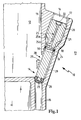
- FIG. 1 shows a valve arrangement 10 for separating water from a housing 11, wherein the housing 11 is only partially shown a closed system represents and separates an inner side 12 of an environmental side 13.
- a drain opening 14 is provided laterally below, which in opened state ( Figure 2) establishes a connection to the drain pipe 15.
- a bore 16 is arranged obliquely, wherein the bore at its lowest Point opens into the drain opening 14.
- an outwardly projecting edge 27 is arranged, wherein from the surrounding side the edge 27, a connection hole 28 is made to the bore 16.
- the hole 16 has an inner thread 17 in an upper region and is in a further reduced area over a cone 18 to a smaller diameter, wherein in the reduced diameter, a radial sealing surface 19 is formed.
- a radial sealing surface 19 is formed in the below Area.
- the arranged in the bore 16 cylinder pin 20 has in the upper part of an external thread 21, which with the internal thread 17 of the Bore 16 is screwed. Tapered below the external thread 21 of the cylindrical pin 20 the cylindrical pin 20 and forms a shaft 29 in the lower region, wherein this has a smaller diameter than the radial sealing surface 19.
- a radial groove 30 which is arranged to receive a Radial sealing ring 24 is used.
- the radial seal 24 a tight connection between the housing inner side 12 and surrounding side 13th ago.
- a sealing element 23 is attached, which due to axial pressure through the cylindrical pin 20 a sealing connection makes with the sealing contour 26 and thus the drain opening 14 opposite the outlet nozzle 15 closes.
- the sealing contour 26 shown is in this embodiment as provided an axial seal.
- This sealing compound can e.g. also about another one O-ring are formed.
- a ventilation hole 25 attached, which by an axial bore 25 a and a radial bore 25b a flow channel between environmental side 13 and a region of the cylindrical pin, which is between radial seal 24 and external thread 21, produces.
- a hexagon socket 22 embossed which is provided for screwing in and out of the cylindrical pin 20.
- valve assembly 10 is shown in the open state.
- the figure 1 corresponding Components are provided with the same reference numerals.
- the cylindrical pin 20 is moved axially upward via the threaded connection, whereby the drain opening 14 is opened to drain pipe 15 out.
- the Cylinderiftes 20th is also the radial sealing ring 24 outside of the radial sealing surface 19, whereby a Flow channel 31 results, which by the hexagon socket 22, the ventilation hole 25 and a gap between the radial sealing surface 19 and the shaft 29 of the cylindrical pin 20 is made.
- the flow channel 31 is in this design through the ventilation hole 25 guaranteed.
- this flow channel by arranging, for example, a longitudinal groove within the external thread 21 or of the internal thread 17 produce.
Landscapes
- Engineering & Computer Science (AREA)
- Chemical & Material Sciences (AREA)
- Chemical Kinetics & Catalysis (AREA)
- Combustion & Propulsion (AREA)
- Mechanical Engineering (AREA)
- General Engineering & Computer Science (AREA)
- Self-Closing Valves And Venting Or Aerating Valves (AREA)
- Details Of Valves (AREA)
- Lift Valve (AREA)
Applications Claiming Priority (2)
| Application Number | Priority Date | Filing Date | Title |
|---|---|---|---|
| DE10359262 | 2003-12-17 | ||
| DE10359262 | 2003-12-17 |
Publications (3)
| Publication Number | Publication Date |
|---|---|
| EP1544453A2 true EP1544453A2 (fr) | 2005-06-22 |
| EP1544453A3 EP1544453A3 (fr) | 2008-07-02 |
| EP1544453B1 EP1544453B1 (fr) | 2017-07-26 |
Family
ID=34485439
Family Applications (1)
| Application Number | Title | Priority Date | Filing Date |
|---|---|---|---|
| EP04106347.0A Expired - Lifetime EP1544453B1 (fr) | 2003-12-17 | 2004-12-07 | Vanne ventilée pour vidange d'eau |
Country Status (1)
| Country | Link |
|---|---|
| EP (1) | EP1544453B1 (fr) |
Cited By (3)
| Publication number | Priority date | Publication date | Assignee | Title |
|---|---|---|---|---|
| WO2014048531A1 (fr) | 2012-09-28 | 2014-04-03 | Daimler Ag | Dispositif de filtration pour moteur à combustion interne |
| DE102021105692A1 (de) | 2021-03-09 | 2022-09-15 | Mann+Hummel Gmbh | Wasserablassvorrichtung, Filtermodul und Verfahren |
| DE102021105694A1 (de) | 2021-03-09 | 2022-09-15 | Mann+Hummel Gmbh | Wasserablassvorrichtung, Filtermodul und Verfahren |
Family Cites Families (2)
| Publication number | Priority date | Publication date | Assignee | Title |
|---|---|---|---|---|
| US5855772A (en) * | 1996-11-01 | 1999-01-05 | Fleetguard, Inc. | Fuel filter and water separator apparatus with heater |
| US6237628B1 (en) * | 2000-07-10 | 2001-05-29 | Fleetguard, Inc. | Self-centering water drain valve |
-
2004
- 2004-12-07 EP EP04106347.0A patent/EP1544453B1/fr not_active Expired - Lifetime
Cited By (5)
| Publication number | Priority date | Publication date | Assignee | Title |
|---|---|---|---|---|
| WO2014048531A1 (fr) | 2012-09-28 | 2014-04-03 | Daimler Ag | Dispositif de filtration pour moteur à combustion interne |
| DE102021105692A1 (de) | 2021-03-09 | 2022-09-15 | Mann+Hummel Gmbh | Wasserablassvorrichtung, Filtermodul und Verfahren |
| DE102021105694A1 (de) | 2021-03-09 | 2022-09-15 | Mann+Hummel Gmbh | Wasserablassvorrichtung, Filtermodul und Verfahren |
| US11794137B2 (en) | 2021-03-09 | 2023-10-24 | Mann+Hummel Gmbh | Water drainage device, filter module, and method |
| US11920547B2 (en) | 2021-03-09 | 2024-03-05 | Mann+Hummel Gmbh | Water drainage device, filter module, and method |
Also Published As
| Publication number | Publication date |
|---|---|
| EP1544453A3 (fr) | 2008-07-02 |
| EP1544453B1 (fr) | 2017-07-26 |
Similar Documents
| Publication | Publication Date | Title |
|---|---|---|
| EP0699826B1 (fr) | Circuit de liquide avec un filtre au courant principal | |
| DE69609975T2 (de) | Wiederverwendbarer flüssigkeitsfilter und adapter. | |
| EP1131542B1 (fr) | Filtre a liquide, notamment pour huile ou carburant de moteur a combustion interne | |
| EP1137470B1 (fr) | Filtre a fluide comportant un dome d'evacuation | |
| EP0699464A2 (fr) | Filtre, notamment pour la purification d'huile de lubrification d'un moteur à combustion interne | |
| DE19700561A1 (de) | Ölfilter | |
| DE10023427A1 (de) | Flüssigkeitsfilter mit in Urformtechnik hergestelltem Gehäuse und Verfahren zu seiner Herstellung | |
| DE19852587A1 (de) | Flüssigkeitsfilter, insbesondere für Öl oder Kraftstoff einer Brennkraftmaschine | |
| DE102013019807A1 (de) | Filtervorrichtung | |
| DE29915844U1 (de) | Filter mit Ventil-Kombinationsbauteil | |
| DE112006003344T5 (de) | Anschluss für eine Kopplungsvorrichtung für Fluidtransfer | |
| DE102012203394B4 (de) | Anschlussblock für Sanitärarmaturen | |
| DE102017106474A1 (de) | Temperaturempfindliche Ventileinrichtung | |
| DE19711457A1 (de) | Ölfilter mit zwei Ölströmen in einem gemeinsamen Gehäuse | |
| EP1544453B1 (fr) | Vanne ventilée pour vidange d'eau | |
| DE102006016318B4 (de) | Schraubenverdichter mit Entlastungsventil | |
| DE102013013487A1 (de) | Flüssigkeitsfilter, insbesondere Kraftstofffilter | |
| DE102015102464B4 (de) | Filter für Hydrauliköl, sowie Spritzgusswerkzeug und Zwischenstück mit diesem Filter | |
| DE20118683U1 (de) | Ölfilter mit Reinölrohr und drei Dichtungen | |
| DE29917563U1 (de) | Fluidfilter mit gehäusefestem Ablassdom | |
| DE29915384U1 (de) | Kombination aus einer Haupteinheit und wenigstens einer Anbau-Funktionseinheit | |
| DE102011015090B4 (de) | Filter | |
| DE202011002327U1 (de) | Trink- und Brauchwassersystem | |
| WO2018065138A1 (fr) | Filtre à liquide | |
| DE102015218320A1 (de) | Ölwanne für eine Antriebsmaschine eines Kraftfahrzeugs sowie Ölschrauben für eine solche Ölwanne |
Legal Events
| Date | Code | Title | Description |
|---|---|---|---|
| PUAI | Public reference made under article 153(3) epc to a published international application that has entered the european phase |
Free format text: ORIGINAL CODE: 0009012 |
|
| AK | Designated contracting states |
Kind code of ref document: A2 Designated state(s): AT BE BG CH CY CZ DE DK EE ES FI FR GB GR HU IE IS IT LI LT LU MC NL PL PT RO SE SI SK TR |
|
| AX | Request for extension of the european patent |
Extension state: AL BA HR LV MK YU |
|
| PUAL | Search report despatched |
Free format text: ORIGINAL CODE: 0009013 |
|
| AK | Designated contracting states |
Kind code of ref document: A3 Designated state(s): AT BE BG CH CY CZ DE DK EE ES FI FR GB GR HU IE IS IT LI LT LU MC NL PL PT RO SE SI SK TR |
|
| AX | Request for extension of the european patent |
Extension state: AL BA HR LV MK YU |
|
| 17P | Request for examination filed |
Effective date: 20080716 |
|
| AKX | Designation fees paid |
Designated state(s): AT BE BG CH CY CZ DE DK EE ES FI FR GB GR HU IE IS IT LI LT LU MC NL PL PT RO SE SI SK TR |
|
| 17Q | First examination report despatched |
Effective date: 20110308 |
|
| GRAP | Despatch of communication of intention to grant a patent |
Free format text: ORIGINAL CODE: EPIDOSNIGR1 |
|
| INTG | Intention to grant announced |
Effective date: 20170306 |
|
| GRAS | Grant fee paid |
Free format text: ORIGINAL CODE: EPIDOSNIGR3 |
|
| GRAA | (expected) grant |
Free format text: ORIGINAL CODE: 0009210 |
|
| RAP1 | Party data changed (applicant data changed or rights of an application transferred) |
Owner name: MANN+HUMMEL GMBH |
|
| AK | Designated contracting states |
Kind code of ref document: B1 Designated state(s): AT BE BG CH CY CZ DE DK EE ES FI FR GB GR HU IE IS IT LI LT LU MC NL PL PT RO SE SI SK TR |
|
| REG | Reference to a national code |
Ref country code: GB Ref legal event code: FG4D Free format text: NOT ENGLISH |
|
| REG | Reference to a national code |
Ref country code: DE Ref legal event code: R081 Ref document number: 502004015566 Country of ref document: DE Owner name: MANN+HUMMEL GMBH, DE Free format text: FORMER OWNER: MANN + HUMMEL GMBH, 71638 LUDWIGSBURG, DE |
|
| REG | Reference to a national code |
Ref country code: CH Ref legal event code: EP |
|
| REG | Reference to a national code |
Ref country code: AT Ref legal event code: REF Ref document number: 912622 Country of ref document: AT Kind code of ref document: T Effective date: 20170815 |
|
| REG | Reference to a national code |
Ref country code: IE Ref legal event code: FG4D Free format text: LANGUAGE OF EP DOCUMENT: GERMAN |
|
| REG | Reference to a national code |
Ref country code: DE Ref legal event code: R096 Ref document number: 502004015566 Country of ref document: DE |
|
| REG | Reference to a national code |
Ref country code: NL Ref legal event code: MP Effective date: 20170726 |
|
| REG | Reference to a national code |
Ref country code: LT Ref legal event code: MG4D |
|
| PG25 | Lapsed in a contracting state [announced via postgrant information from national office to epo] |
Ref country code: FI Free format text: LAPSE BECAUSE OF FAILURE TO SUBMIT A TRANSLATION OF THE DESCRIPTION OR TO PAY THE FEE WITHIN THE PRESCRIBED TIME-LIMIT Effective date: 20170726 Ref country code: LT Free format text: LAPSE BECAUSE OF FAILURE TO SUBMIT A TRANSLATION OF THE DESCRIPTION OR TO PAY THE FEE WITHIN THE PRESCRIBED TIME-LIMIT Effective date: 20170726 Ref country code: SE Free format text: LAPSE BECAUSE OF FAILURE TO SUBMIT A TRANSLATION OF THE DESCRIPTION OR TO PAY THE FEE WITHIN THE PRESCRIBED TIME-LIMIT Effective date: 20170726 Ref country code: NL Free format text: LAPSE BECAUSE OF FAILURE TO SUBMIT A TRANSLATION OF THE DESCRIPTION OR TO PAY THE FEE WITHIN THE PRESCRIBED TIME-LIMIT Effective date: 20170726 |
|
| PG25 | Lapsed in a contracting state [announced via postgrant information from national office to epo] |
Ref country code: ES Free format text: LAPSE BECAUSE OF FAILURE TO SUBMIT A TRANSLATION OF THE DESCRIPTION OR TO PAY THE FEE WITHIN THE PRESCRIBED TIME-LIMIT Effective date: 20170726 Ref country code: IS Free format text: LAPSE BECAUSE OF FAILURE TO SUBMIT A TRANSLATION OF THE DESCRIPTION OR TO PAY THE FEE WITHIN THE PRESCRIBED TIME-LIMIT Effective date: 20171126 Ref country code: PL Free format text: LAPSE BECAUSE OF FAILURE TO SUBMIT A TRANSLATION OF THE DESCRIPTION OR TO PAY THE FEE WITHIN THE PRESCRIBED TIME-LIMIT Effective date: 20170726 Ref country code: BG Free format text: LAPSE BECAUSE OF FAILURE TO SUBMIT A TRANSLATION OF THE DESCRIPTION OR TO PAY THE FEE WITHIN THE PRESCRIBED TIME-LIMIT Effective date: 20171026 Ref country code: GR Free format text: LAPSE BECAUSE OF FAILURE TO SUBMIT A TRANSLATION OF THE DESCRIPTION OR TO PAY THE FEE WITHIN THE PRESCRIBED TIME-LIMIT Effective date: 20171027 |
|
| PG25 | Lapsed in a contracting state [announced via postgrant information from national office to epo] |
Ref country code: CZ Free format text: LAPSE BECAUSE OF FAILURE TO SUBMIT A TRANSLATION OF THE DESCRIPTION OR TO PAY THE FEE WITHIN THE PRESCRIBED TIME-LIMIT Effective date: 20170726 Ref country code: RO Free format text: LAPSE BECAUSE OF FAILURE TO SUBMIT A TRANSLATION OF THE DESCRIPTION OR TO PAY THE FEE WITHIN THE PRESCRIBED TIME-LIMIT Effective date: 20170726 Ref country code: DK Free format text: LAPSE BECAUSE OF FAILURE TO SUBMIT A TRANSLATION OF THE DESCRIPTION OR TO PAY THE FEE WITHIN THE PRESCRIBED TIME-LIMIT Effective date: 20170726 |
|
| REG | Reference to a national code |
Ref country code: DE Ref legal event code: R097 Ref document number: 502004015566 Country of ref document: DE |
|
| PG25 | Lapsed in a contracting state [announced via postgrant information from national office to epo] |
Ref country code: SK Free format text: LAPSE BECAUSE OF FAILURE TO SUBMIT A TRANSLATION OF THE DESCRIPTION OR TO PAY THE FEE WITHIN THE PRESCRIBED TIME-LIMIT Effective date: 20170726 Ref country code: IT Free format text: LAPSE BECAUSE OF FAILURE TO SUBMIT A TRANSLATION OF THE DESCRIPTION OR TO PAY THE FEE WITHIN THE PRESCRIBED TIME-LIMIT Effective date: 20170726 Ref country code: EE Free format text: LAPSE BECAUSE OF FAILURE TO SUBMIT A TRANSLATION OF THE DESCRIPTION OR TO PAY THE FEE WITHIN THE PRESCRIBED TIME-LIMIT Effective date: 20170726 |
|
| PLBE | No opposition filed within time limit |
Free format text: ORIGINAL CODE: 0009261 |
|
| STAA | Information on the status of an ep patent application or granted ep patent |
Free format text: STATUS: NO OPPOSITION FILED WITHIN TIME LIMIT |
|
| 26N | No opposition filed |
Effective date: 20180430 |
|
| REG | Reference to a national code |
Ref country code: DE Ref legal event code: R081 Ref document number: 502004015566 Country of ref document: DE Owner name: MANN+HUMMEL GMBH, DE Free format text: FORMER OWNER: MANN + HUMMEL GMBH, 71636 LUDWIGSBURG, DE |
|
| REG | Reference to a national code |
Ref country code: CH Ref legal event code: PL |
|
| GBPC | Gb: european patent ceased through non-payment of renewal fee |
Effective date: 20171207 |
|
| PG25 | Lapsed in a contracting state [announced via postgrant information from national office to epo] |
Ref country code: SI Free format text: LAPSE BECAUSE OF FAILURE TO SUBMIT A TRANSLATION OF THE DESCRIPTION OR TO PAY THE FEE WITHIN THE PRESCRIBED TIME-LIMIT Effective date: 20170726 |
|
| REG | Reference to a national code |
Ref country code: IE Ref legal event code: MM4A |
|
| PG25 | Lapsed in a contracting state [announced via postgrant information from national office to epo] |
Ref country code: LU Free format text: LAPSE BECAUSE OF NON-PAYMENT OF DUE FEES Effective date: 20171207 |
|
| REG | Reference to a national code |
Ref country code: FR Ref legal event code: ST Effective date: 20180831 |
|
| REG | Reference to a national code |
Ref country code: BE Ref legal event code: MM Effective date: 20171231 |
|
| PG25 | Lapsed in a contracting state [announced via postgrant information from national office to epo] |
Ref country code: FR Free format text: LAPSE BECAUSE OF NON-PAYMENT OF DUE FEES Effective date: 20180102 Ref country code: IE Free format text: LAPSE BECAUSE OF NON-PAYMENT OF DUE FEES Effective date: 20171207 |
|
| PG25 | Lapsed in a contracting state [announced via postgrant information from national office to epo] |
Ref country code: BE Free format text: LAPSE BECAUSE OF NON-PAYMENT OF DUE FEES Effective date: 20171231 Ref country code: LI Free format text: LAPSE BECAUSE OF NON-PAYMENT OF DUE FEES Effective date: 20171231 Ref country code: GB Free format text: LAPSE BECAUSE OF NON-PAYMENT OF DUE FEES Effective date: 20171207 Ref country code: CH Free format text: LAPSE BECAUSE OF NON-PAYMENT OF DUE FEES Effective date: 20171231 |
|
| REG | Reference to a national code |
Ref country code: AT Ref legal event code: MM01 Ref document number: 912622 Country of ref document: AT Kind code of ref document: T Effective date: 20171207 |
|
| PG25 | Lapsed in a contracting state [announced via postgrant information from national office to epo] |
Ref country code: AT Free format text: LAPSE BECAUSE OF NON-PAYMENT OF DUE FEES Effective date: 20171207 |
|
| PG25 | Lapsed in a contracting state [announced via postgrant information from national office to epo] |
Ref country code: HU Free format text: LAPSE BECAUSE OF FAILURE TO SUBMIT A TRANSLATION OF THE DESCRIPTION OR TO PAY THE FEE WITHIN THE PRESCRIBED TIME-LIMIT; INVALID AB INITIO Effective date: 20041207 Ref country code: MC Free format text: LAPSE BECAUSE OF FAILURE TO SUBMIT A TRANSLATION OF THE DESCRIPTION OR TO PAY THE FEE WITHIN THE PRESCRIBED TIME-LIMIT Effective date: 20170726 |
|
| PG25 | Lapsed in a contracting state [announced via postgrant information from national office to epo] |
Ref country code: CY Free format text: LAPSE BECAUSE OF NON-PAYMENT OF DUE FEES Effective date: 20170726 |
|
| PG25 | Lapsed in a contracting state [announced via postgrant information from national office to epo] |
Ref country code: TR Free format text: LAPSE BECAUSE OF FAILURE TO SUBMIT A TRANSLATION OF THE DESCRIPTION OR TO PAY THE FEE WITHIN THE PRESCRIBED TIME-LIMIT Effective date: 20170726 |
|
| PG25 | Lapsed in a contracting state [announced via postgrant information from national office to epo] |
Ref country code: PT Free format text: LAPSE BECAUSE OF FAILURE TO SUBMIT A TRANSLATION OF THE DESCRIPTION OR TO PAY THE FEE WITHIN THE PRESCRIBED TIME-LIMIT Effective date: 20170726 |
|
| P01 | Opt-out of the competence of the unified patent court (upc) registered |
Effective date: 20230803 |
|
| PGFP | Annual fee paid to national office [announced via postgrant information from national office to epo] |
Ref country code: DE Payment date: 20231214 Year of fee payment: 20 |
|
| REG | Reference to a national code |
Ref country code: DE Ref legal event code: R071 Ref document number: 502004015566 Country of ref document: DE |