EP1544453B1 - Vanne ventilée pour vidange d'eau - Google Patents
Vanne ventilée pour vidange d'eau Download PDFInfo
- Publication number
- EP1544453B1 EP1544453B1 EP04106347.0A EP04106347A EP1544453B1 EP 1544453 B1 EP1544453 B1 EP 1544453B1 EP 04106347 A EP04106347 A EP 04106347A EP 1544453 B1 EP1544453 B1 EP 1544453B1
- Authority
- EP
- European Patent Office
- Prior art keywords
- cylindrical
- borehole
- disposed
- drain opening
- cylindrical pin
- Prior art date
- Legal status (The legal status is an assumption and is not a legal conclusion. Google has not performed a legal analysis and makes no representation as to the accuracy of the status listed.)
- Active
Links
- XLYOFNOQVPJJNP-UHFFFAOYSA-N water Substances O XLYOFNOQVPJJNP-UHFFFAOYSA-N 0.000 title claims description 26
- 238000007789 sealing Methods 0.000 claims description 25
- 239000000446 fuel Substances 0.000 claims description 19
- 238000000034 method Methods 0.000 claims description 4
- 238000006073 displacement reaction Methods 0.000 claims description 2
- 239000003570 air Substances 0.000 description 8
- 238000007599 discharging Methods 0.000 description 6
- 238000013461 design Methods 0.000 description 4
- 238000009434 installation Methods 0.000 description 4
- 239000007788 liquid Substances 0.000 description 4
- 239000012080 ambient air Substances 0.000 description 3
- 230000007613 environmental effect Effects 0.000 description 3
- 238000012423 maintenance Methods 0.000 description 3
- 238000009423 ventilation Methods 0.000 description 3
- 238000002485 combustion reaction Methods 0.000 description 2
- 229910052751 metal Inorganic materials 0.000 description 2
- 239000002184 metal Substances 0.000 description 2
- 238000000465 moulding Methods 0.000 description 2
- 239000004033 plastic Substances 0.000 description 2
- 238000000926 separation method Methods 0.000 description 2
- 239000004952 Polyamide Substances 0.000 description 1
- 229910052782 aluminium Inorganic materials 0.000 description 1
- XAGFODPZIPBFFR-UHFFFAOYSA-N aluminium Chemical compound [Al] XAGFODPZIPBFFR-UHFFFAOYSA-N 0.000 description 1
- 238000013459 approach Methods 0.000 description 1
- 239000012223 aqueous fraction Substances 0.000 description 1
- 238000011109 contamination Methods 0.000 description 1
- 239000000428 dust Substances 0.000 description 1
- 230000000694 effects Effects 0.000 description 1
- 238000001746 injection moulding Methods 0.000 description 1
- 230000010354 integration Effects 0.000 description 1
- 239000002245 particle Substances 0.000 description 1
- 229920002647 polyamide Polymers 0.000 description 1
- 238000013022 venting Methods 0.000 description 1
Images

Classifications
-
- B—PERFORMING OPERATIONS; TRANSPORTING
- B01—PHYSICAL OR CHEMICAL PROCESSES OR APPARATUS IN GENERAL
- B01D—SEPARATION
- B01D36/00—Filter circuits or combinations of filters with other separating devices
- B01D36/003—Filters in combination with devices for the removal of liquids
- B01D36/006—Purge means
-
- F—MECHANICAL ENGINEERING; LIGHTING; HEATING; WEAPONS; BLASTING
- F02—COMBUSTION ENGINES; HOT-GAS OR COMBUSTION-PRODUCT ENGINE PLANTS
- F02M—SUPPLYING COMBUSTION ENGINES IN GENERAL WITH COMBUSTIBLE MIXTURES OR CONSTITUENTS THEREOF
- F02M37/00—Apparatus or systems for feeding liquid fuel from storage containers to carburettors or fuel-injection apparatus; Arrangements for purifying liquid fuel specially adapted for, or arranged on, internal-combustion engines
- F02M37/22—Arrangements for purifying liquid fuel specially adapted for, or arranged on, internal-combustion engines, e.g. arrangements in the feeding system
- F02M37/24—Arrangements for purifying liquid fuel specially adapted for, or arranged on, internal-combustion engines, e.g. arrangements in the feeding system characterised by water separating means
Definitions
- the invention relates to a valve arrangement for discharging water from the housing of a fuel filter. Since an occurrence of water fractions in the fuel of internal combustion engines is unavoidable, the water components accumulate due to their specific heavier weight than that of fuel usually at the lowest point of a container. In order to avoid that this separated amount of water exceeds a level and is continued in the fuel system, this amount of water must be discharged at intervals during maintenance. As a container in the fuel system, which allows the separation of the water, usually the fuel filter is used. For simplicity, a screw is placed in the lower part of the fuel filter, which closes an opening. By opening this screw, the water is drained during maintenance. The problem with this design is that the water can only drain, if at the same time air enters the system again.
- the document WO 98/19770 A discloses a valve arrangement for discharging water from the housing of a fuel filter.
- the valve arrangement consists of a cylindrical bore, on which a discharge opening is arranged at a lateral low point.
- a connection hole to the filter housing interior is arranged in the cylindrical bore, such that the cylindrical pin closes the drain opening with a mounted in the end face sealing element by an axial pressure and at the same time closes the bore in the region above the connecting hole by a cylinder pin arranged on the radial seal.
- the cylinder pin In a dissolved state, the cylinder pin is axially displaced, so that the sealing element the At the same time the radial seal opens the cylindrical bore to the surrounding side.
- the object of the present invention is to provide a valve assembly in a fuel filter, which the uniform drainage of the water by simple Operation in an easily accessible location allows. This object is solved by the features of claims 1 and 8.
- the valve arrangement according to the invention for discharging water from the housing of a fuel filter is particularly suitable for use in the fuel line system of an internal combustion engine.
- a drain opening is attached laterally in the deep area, which is provided for draining the water.
- a cylindrical bore is mounted laterally on the housing, which opens into the drain opening of the housing.
- a connection hole At a geodetically higher area of the cylindrical bore is a connection hole, which leads into the housing interior.
- the cylindrical bore terminates at the environmental side of the closed housing.
- a cylinder pin is mounted when the valve state is closed, which closes the drain opening by a sealing element attached to the end face.
- the housing with the described corresponding components may be integrally or composed of several parts. Preferably, it is in a primary molding of a light metal, for. As aluminum, or plastic, such as polyamide. produced.
- a light metal for. As aluminum, or plastic, such as polyamide. produced.
- both the drain opening and a connecting cross-section for the subsequent flow of air are closed by a cylindrical pin. Since the drain opening is arranged at a lower point and the cylinder pin is arranged due to the higher connection hole for air supply above the drain opening, the accessible side of the cylinder pin is to be operated on the top and thus from above. This ensures convenient accessibility in the usual installation positions.
- the cylindrical pin is axially displaceable in the cylindrical bore, whereby the valve assembly can be placed in an open state.
- the distance between the front-side sealing element of the cylinder pin and the radial seal arranged above the connecting hole is tuned such that the discharge opening is opened in the open state by the frontal sealing element, and the radial seal at the same time an inflow between cylindrical bore and connecting hole releases.
- the opening of this connection cross-section can be achieved in that between cylindrical bore and cylinder pin, an annular gap is present and the radial seal guided in axial movement over an edge to a larger diameter and thereby the sealing effect of the radial seal is repealed.
- the cylindrical pin can optionally be made of plastic or metal.
- the cylindrical bore is arranged laterally obliquely in the housing wall, wherein the bore also opens laterally in the discharge opening in this embodiment.
- This version is particularly recommended if the housing is manufactured using the primary molding process, in particular by injection molding. In this case, the required geometry for the wall of the bore in the mold can be considered.
- An advantage of this embodiment is that the drain opening does not necessarily have to be arranged outside the inside of the housing, but can be flush with the housing wall or even slightly offset from the edge of the housing can be set inwards. By this arrangement, which comes as close as possible to a central arrangement of the drain opening, a more optimal flow of the settled water is allowed, and there are any existing dirt particles flushed out at the same time.
- the cylindrical bore extends closer to the inside of the housing and thereby results in an advantage with respect to the installation space. Improved is the accessibility of the cylindrical bore, which results in the oblique arrangement of the bore mouth more space for possible installation work.
- a further advantageous embodiment of the inventive concept results in particular in the previously described, obliquely arranged cylindrical bore by the design of the inner geometry of the housing.
- the connection hole between the inside of the housing and the cylindrical bore can be formed by an edge protruding from the inside to the outside. If the cylindrical bore is adjusted in such a way that the bore is tangent to the outwardly projecting edge, then, after the blank has been produced by making the cylindrical bore, the connecting hole to the inside of the housing can be produced at the same time.
- the cylindrical bore and the connection hole are produced in one operation. Because the connection hole is made by an outwardly projecting edge, which is open at the top, it is possible to construct this design without an undercut.
- the inventive embodiment of the cylinder pin is made possible by the attachment of a longitudinal bore in the cylinder pin, wherein the longitudinal bore is open to the surrounding side and communicates with a transverse bore above the radial seal. Through this hole, a flow channel for ventilation between the environment side and the connection hole can be made. Thus, an advantageous, defined Nachströmung the ambient air is ensured by the cylinder pin.
- Another embodiment of the cylinder pin according to the invention results from the attachment of a longitudinal groove on the external thread, which is arranged in the region above the radial seal of the cylinder pin.
- a longitudinal groove on the external thread which is arranged in the region above the radial seal of the cylinder pin.
- this cylinder pin provided with an external thread, which communicates with an internal thread of the cylindrical bore, so the axial movement and the necessary axial fastening force can be effected by turning the cylinder pin and.
- This threaded connection of the cylinder pin with the housing can be mounted at the upper end of the cylindrical bore or the cylinder pin Obviously.
- the cylinder pin can be recessed in the cylindrical bore in the screwed state, in which case a hexagon socket or a slot contour for rotating the cylindrical pin is necessary. In the embodiment of the hexagon socket with centric ventilation bore, the metering of the air flow is also made possible by a hexagonal tool. With recessed cylinder pin it is recommended to close the cylindrical bore with a removable dust cover.
- a further advantageous embodiment of the invention results from the arrangement of a downcomer, which communicates with the drain opening and which allows connecting elements to a continuing line system.
- a downcomer which communicates with the drain opening and which allows connecting elements to a continuing line system.
- the inventive method for discharging water from a housing of a fuel filter makes it possible by the displacement of a cylinder pin at the same time to open a lower drain opening in the housing and to produce a connecting cross-section for Nachströmung of ambient air.
- the cylinder pin is hereby moved by rotational movement via a threaded connection or by a lever mechanism from a closed position to an open position.
- the drain opening is opened by the axial release of a front side mounted on the cylinder pin sealing element and at the same time released between the cylinder pin and a bore mounted radial seal.
- the drainage of liquid from the closed housing creates a relative negative pressure in the housing, whereby the ambient air can flow through the cylindrical bore past the cylinder pin through the connection hole in the housing.
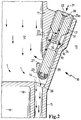
- FIG. 1 a valve assembly 10 for the separation of water from a housing 11 is shown, wherein the partially illustrated housing 11 is a closed system and an inner side 12 separates from an environmental side 13.
- a drain opening 14 is provided laterally below, which in the open state ( FIG. 2 ) establishes a connection to the drain pipe 15.
- a bore 16 is arranged obliquely, wherein the bore opens at its lowest point in the drain opening 14.
- an outwardly projecting edge 27 is arranged, wherein from the surrounding side of the edge 27, a connection hole 28 is made to the bore 16.
- the bore 16 has an inner thread 17 in an upper region and is reduced in a region lying further down via a cone 18 to a smaller diameter, wherein a radial sealing surface 19 is formed in the reduced diameter.
- the bore 16 opens in a sealing contour 26, which also communicates with the drain opening 14.
- the arranged in the bore 16 cylinder pin 20 has an external thread 21 in the upper region, which is screwed to the internal thread 17 of the bore 16.
- Below the external thread 21 of the cylindrical pin 20, the cylindrical pin 20 tapers and forms in the lower region a shaft 29, wherein this has a smaller diameter than the radial sealing surface 19.
- a radial groove 30 is arranged, which serves to receive a radial sealing ring 24.
- the radial seal 24 provides a tight connection between the housing inner side 12 and the surrounding side 13 ago.
- a sealing element 23 is mounted, which establishes a sealing connection with the sealing contour 26 due to axial pressure through the cylindrical pin 20 and thus closes the drain opening 14 relative to the outlet nozzle 15.
- the sealing contour 26 shown is provided in this embodiment as an axial seal.
- This sealing connection can also be formed, for example, via a further O-ring.
- a vent hole 25 is mounted, which through an axial bore 25 a and a radial bore 25 b, a flow channel between the environmental side 13 and a region of the cylindrical pin, which is between the radial seal 24 and external thread 21, produces.
- a hexagon socket profile 22 is impressed, which is provided for screwing in and out of the cylindrical pin 20.
- FIG. 2 the valve assembly 10 is shown in the open state.
- corresponding components are provided with the same reference numerals.
- the cylinder pin 20 is moved axially upwards via the threaded connection, as a result of which the discharge opening 14 is opened towards the discharge connection 15. Due to the axial movement of the cylinder pin 20 and the radial seal 24 is outside the radial sealing surface 19, resulting in a flow channel 31, which is made by the hexagon socket 22, the vent hole 25 and a gap between the radial sealing surface 19 and the shaft 29 of the cylindrical pin 20 ,
- the flow channel 31 is ensured by the ventilation hole 25 in this design.
- it is also possible to produce this flow channel by arranging, for example, a longitudinal groove within the external thread 21 or the internal thread 17.
Landscapes
- Engineering & Computer Science (AREA)
- Chemical & Material Sciences (AREA)
- Chemical Kinetics & Catalysis (AREA)
- Combustion & Propulsion (AREA)
- Mechanical Engineering (AREA)
- General Engineering & Computer Science (AREA)
- Self-Closing Valves And Venting Or Aerating Valves (AREA)
- Details Of Valves (AREA)
- Lift Valve (AREA)
Claims (7)
- Ensemble de soupapes destiné à évacuer de l'eau du boîtier d'un filtre à carburant, comprenant le boîtier de filtre (11) au point latéral le plus bas duquel est disposée une ouverture d'évacuation (14), un trou de forage cylindrique (16) débouchant simultanément dans l'ouverture d'évacuation (14), lequel est positionné dans la paroi du boîtier de filtre et établit une liaison avec le côté environnement (13), un trou de jonction (28) menant à l'intérieur du boîtier de filtre (12) étant placé dans le trou de forage cylindrique (16) à un point géodésiquement situé au-dessus de l'ouverture d'évacuation (14), une goupille cylindrique (20) mobile en sens axial étant positionnée dans le trou de forage (16) de sorte que la goupille cylindrique (20) obture, sous l'effet d'une pression axiale, l'ouverture d'évacuation (14) avec un élément d'étanchéité (23) monté sur la face frontale et ferme simultanément le trou de forage (16), dans la zone située au-dessus du trou de jonction (28), par un joint radial (24) placé sur la goupille cylindrique (20), la goupille cylindrique (20) étant décalée en sens axial à l'état desserré, de sorte que l'élément d'étanchéité (23) ouvre l'ouverture d'évacuation (14) et que, simultanément, le joint radial (24) ouvre le trou de forage cylindrique (16) vers le côté environnement (13), au moins un trou de forage (25) prévu dans la goupille cylindrique (20) ou une rainure longitudinale prévue sur la goupille cylindrique (20) générant un canal d'écoulement vers le côté environnement.
- Ensemble de soupapes selon la revendication 1, caractérisé en ce que le trou de forage cylindrique (16) est disposé de manière oblique dans le boîtier de filtre (11).
- Ensemble de soupapes selon la revendication 2, caractérisé en ce que le trou de jonction (28) est formé par un bord (27) en saillie vers l'extérieur placé dans le boîtier de filtre (11).
- Ensemble de soupapes selon l'une des revendications précédentes, caractérisé en ce que le mouvement et la fixation de la goupille cylindrique (20) dans le trou de forage (16) sont assurés par un assemblage fileté (17, 21).
- Ensemble de soupapes selon l'une des revendications précédentes, caractérisé en ce que l'ouverture d'évacuation (14) mène à une tubulure d'évacuation (15) et que cette tubulure est reliée à un système de tuyauteries.
- Filtre à carburant, comprenant un ensemble de soupapes selon l'une des revendications 1 à 5.
- Procédé destiné à évacuer de l'eau du boîtier d'un filtre à carburant, une goupille cylindrique étant positionnée dans un trou de forage cylindrique disposé dans le boîtier de filtre, cette goupille obturant avec un élément d'étanchéité une ouverture d'évacuation située au point le plus bas du boîtier de filtre et obturant avec un joint radial le trou de forage cylindrique, le décalage en sens axial de la goupille cylindrique permettant d'ouvrir l'ouverture d'évacuation et simultanément un canal d'écoulement du trou de forage cylindrique, un trou de jonction étant placé au-dessus de l'ouverture d'évacuation et communiquant avec le trou de forage cylindrique, l'élément d'étanchéité ouvrant l'ouverture d'évacuation et le joint radial ouvrant simultanément le trou de forage cylindrique vers le côté environnement, au moins un trou de forage prévu dans la goupille cylindrique ou une rainure longitudinale prévue sur la goupille cylindrique générant un canal d'écoulement vers le côté environnement, ce qui permet un écoulement de l'eau à travers l'ouverture d'évacuation et simultanément l'arrivée d'air à travers le trou de forage cylindrique et le trou de jonction.
Applications Claiming Priority (2)
| Application Number | Priority Date | Filing Date | Title |
|---|---|---|---|
| DE10359262 | 2003-12-17 | ||
| DE10359262 | 2003-12-17 |
Publications (3)
| Publication Number | Publication Date |
|---|---|
| EP1544453A2 EP1544453A2 (fr) | 2005-06-22 |
| EP1544453A3 EP1544453A3 (fr) | 2008-07-02 |
| EP1544453B1 true EP1544453B1 (fr) | 2017-07-26 |
Family
ID=34485439
Family Applications (1)
| Application Number | Title | Priority Date | Filing Date |
|---|---|---|---|
| EP04106347.0A Active EP1544453B1 (fr) | 2003-12-17 | 2004-12-07 | Vanne ventilée pour vidange d'eau |
Country Status (1)
| Country | Link |
|---|---|
| EP (1) | EP1544453B1 (fr) |
Families Citing this family (3)
| Publication number | Priority date | Publication date | Assignee | Title |
|---|---|---|---|---|
| US20140091026A1 (en) | 2012-09-28 | 2014-04-03 | Oliver Lambert | Filter apparatus for an internal combustion engine |
| DE102021105692A1 (de) | 2021-03-09 | 2022-09-15 | Mann+Hummel Gmbh | Wasserablassvorrichtung, Filtermodul und Verfahren |
| DE102021105694A1 (de) | 2021-03-09 | 2022-09-15 | Mann+Hummel Gmbh | Wasserablassvorrichtung, Filtermodul und Verfahren |
Family Cites Families (2)
| Publication number | Priority date | Publication date | Assignee | Title |
|---|---|---|---|---|
| US5855772A (en) * | 1996-11-01 | 1999-01-05 | Fleetguard, Inc. | Fuel filter and water separator apparatus with heater |
| US6237628B1 (en) * | 2000-07-10 | 2001-05-29 | Fleetguard, Inc. | Self-centering water drain valve |
-
2004
- 2004-12-07 EP EP04106347.0A patent/EP1544453B1/fr active Active
Also Published As
| Publication number | Publication date |
|---|---|
| EP1544453A2 (fr) | 2005-06-22 |
| EP1544453A3 (fr) | 2008-07-02 |
Similar Documents
| Publication | Publication Date | Title |
|---|---|---|
| DE69609975T2 (de) | Wiederverwendbarer flüssigkeitsfilter und adapter. | |
| EP1131542B1 (fr) | Filtre a liquide, notamment pour huile ou carburant de moteur a combustion interne | |
| EP1137470B1 (fr) | Filtre a fluide comportant un dome d'evacuation | |
| EP0699826B1 (fr) | Circuit de liquide avec un filtre au courant principal | |
| EP1154831B1 (fr) | Filtre a liquide comprenant un element central demontable et un element de maintien supplementaire | |
| EP0748646B1 (fr) | Filtre de liquide | |
| EP2102484B1 (fr) | Filtre à carburant d'un moteur à combustion de véhicule | |
| DE4428771A1 (de) | Filter, insbesondere zum Reinigen von Schmieröl einer Brennkraftmaschine | |
| EP1110590A2 (fr) | Filtre de liquide à dispositif de vidange de résidus liquides | |
| DE19700561A1 (de) | Ölfilter | |
| EP3096859B1 (fr) | Élément de filtration | |
| DE19538883A1 (de) | Filter für Flüssigkeiten, insbesondere Dieselkraftstoff | |
| DE19852587A1 (de) | Flüssigkeitsfilter, insbesondere für Öl oder Kraftstoff einer Brennkraftmaschine | |
| DE19961579A1 (de) | Flüssigkeitsfilter mit einem Kühler | |
| DE2528932A1 (de) | Filteranordnung | |
| EP1544453B1 (fr) | Vanne ventilée pour vidange d'eau | |
| DE112014006491T5 (de) | Filterregler | |
| DE102013013487A1 (de) | Flüssigkeitsfilter, insbesondere Kraftstofffilter | |
| EP2129902B1 (fr) | Filtre pour liquides | |
| DE102013210065A1 (de) | Filtereinrichtung, insbesondere für ein Kraftfahrzeug | |
| EP4357000A2 (fr) | Dispositif filtre | |
| DE1812592A1 (de) | Selbsttaetig arbeitendes Entleerungsventil | |
| DE102014010007A1 (de) | Filtervorrichtung | |
| DE102011015090B4 (de) | Filter | |
| DE29917563U1 (de) | Fluidfilter mit gehäusefestem Ablassdom |
Legal Events
| Date | Code | Title | Description |
|---|---|---|---|
| PUAI | Public reference made under article 153(3) epc to a published international application that has entered the european phase |
Free format text: ORIGINAL CODE: 0009012 |
|
| AK | Designated contracting states |
Kind code of ref document: A2 Designated state(s): AT BE BG CH CY CZ DE DK EE ES FI FR GB GR HU IE IS IT LI LT LU MC NL PL PT RO SE SI SK TR |
|
| AX | Request for extension of the european patent |
Extension state: AL BA HR LV MK YU |
|
| PUAL | Search report despatched |
Free format text: ORIGINAL CODE: 0009013 |
|
| AK | Designated contracting states |
Kind code of ref document: A3 Designated state(s): AT BE BG CH CY CZ DE DK EE ES FI FR GB GR HU IE IS IT LI LT LU MC NL PL PT RO SE SI SK TR |
|
| AX | Request for extension of the european patent |
Extension state: AL BA HR LV MK YU |
|
| 17P | Request for examination filed |
Effective date: 20080716 |
|
| AKX | Designation fees paid |
Designated state(s): AT BE BG CH CY CZ DE DK EE ES FI FR GB GR HU IE IS IT LI LT LU MC NL PL PT RO SE SI SK TR |
|
| 17Q | First examination report despatched |
Effective date: 20110308 |
|
| GRAP | Despatch of communication of intention to grant a patent |
Free format text: ORIGINAL CODE: EPIDOSNIGR1 |
|
| INTG | Intention to grant announced |
Effective date: 20170306 |
|
| GRAS | Grant fee paid |
Free format text: ORIGINAL CODE: EPIDOSNIGR3 |
|
| GRAA | (expected) grant |
Free format text: ORIGINAL CODE: 0009210 |
|
| RAP1 | Party data changed (applicant data changed or rights of an application transferred) |
Owner name: MANN+HUMMEL GMBH |
|
| AK | Designated contracting states |
Kind code of ref document: B1 Designated state(s): AT BE BG CH CY CZ DE DK EE ES FI FR GB GR HU IE IS IT LI LT LU MC NL PL PT RO SE SI SK TR |
|
| REG | Reference to a national code |
Ref country code: GB Ref legal event code: FG4D Free format text: NOT ENGLISH |
|
| REG | Reference to a national code |
Ref country code: DE Ref legal event code: R081 Ref document number: 502004015566 Country of ref document: DE Owner name: MANN+HUMMEL GMBH, DE Free format text: FORMER OWNER: MANN + HUMMEL GMBH, 71638 LUDWIGSBURG, DE |
|
| REG | Reference to a national code |
Ref country code: CH Ref legal event code: EP |
|
| REG | Reference to a national code |
Ref country code: AT Ref legal event code: REF Ref document number: 912622 Country of ref document: AT Kind code of ref document: T Effective date: 20170815 |
|
| REG | Reference to a national code |
Ref country code: IE Ref legal event code: FG4D Free format text: LANGUAGE OF EP DOCUMENT: GERMAN |
|
| REG | Reference to a national code |
Ref country code: DE Ref legal event code: R096 Ref document number: 502004015566 Country of ref document: DE |
|
| REG | Reference to a national code |
Ref country code: NL Ref legal event code: MP Effective date: 20170726 |
|
| REG | Reference to a national code |
Ref country code: LT Ref legal event code: MG4D |
|
| PG25 | Lapsed in a contracting state [announced via postgrant information from national office to epo] |
Ref country code: FI Free format text: LAPSE BECAUSE OF FAILURE TO SUBMIT A TRANSLATION OF THE DESCRIPTION OR TO PAY THE FEE WITHIN THE PRESCRIBED TIME-LIMIT Effective date: 20170726 Ref country code: LT Free format text: LAPSE BECAUSE OF FAILURE TO SUBMIT A TRANSLATION OF THE DESCRIPTION OR TO PAY THE FEE WITHIN THE PRESCRIBED TIME-LIMIT Effective date: 20170726 Ref country code: SE Free format text: LAPSE BECAUSE OF FAILURE TO SUBMIT A TRANSLATION OF THE DESCRIPTION OR TO PAY THE FEE WITHIN THE PRESCRIBED TIME-LIMIT Effective date: 20170726 Ref country code: NL Free format text: LAPSE BECAUSE OF FAILURE TO SUBMIT A TRANSLATION OF THE DESCRIPTION OR TO PAY THE FEE WITHIN THE PRESCRIBED TIME-LIMIT Effective date: 20170726 |
|
| PG25 | Lapsed in a contracting state [announced via postgrant information from national office to epo] |
Ref country code: ES Free format text: LAPSE BECAUSE OF FAILURE TO SUBMIT A TRANSLATION OF THE DESCRIPTION OR TO PAY THE FEE WITHIN THE PRESCRIBED TIME-LIMIT Effective date: 20170726 Ref country code: IS Free format text: LAPSE BECAUSE OF FAILURE TO SUBMIT A TRANSLATION OF THE DESCRIPTION OR TO PAY THE FEE WITHIN THE PRESCRIBED TIME-LIMIT Effective date: 20171126 Ref country code: PL Free format text: LAPSE BECAUSE OF FAILURE TO SUBMIT A TRANSLATION OF THE DESCRIPTION OR TO PAY THE FEE WITHIN THE PRESCRIBED TIME-LIMIT Effective date: 20170726 Ref country code: BG Free format text: LAPSE BECAUSE OF FAILURE TO SUBMIT A TRANSLATION OF THE DESCRIPTION OR TO PAY THE FEE WITHIN THE PRESCRIBED TIME-LIMIT Effective date: 20171026 Ref country code: GR Free format text: LAPSE BECAUSE OF FAILURE TO SUBMIT A TRANSLATION OF THE DESCRIPTION OR TO PAY THE FEE WITHIN THE PRESCRIBED TIME-LIMIT Effective date: 20171027 |
|
| PG25 | Lapsed in a contracting state [announced via postgrant information from national office to epo] |
Ref country code: CZ Free format text: LAPSE BECAUSE OF FAILURE TO SUBMIT A TRANSLATION OF THE DESCRIPTION OR TO PAY THE FEE WITHIN THE PRESCRIBED TIME-LIMIT Effective date: 20170726 Ref country code: RO Free format text: LAPSE BECAUSE OF FAILURE TO SUBMIT A TRANSLATION OF THE DESCRIPTION OR TO PAY THE FEE WITHIN THE PRESCRIBED TIME-LIMIT Effective date: 20170726 Ref country code: DK Free format text: LAPSE BECAUSE OF FAILURE TO SUBMIT A TRANSLATION OF THE DESCRIPTION OR TO PAY THE FEE WITHIN THE PRESCRIBED TIME-LIMIT Effective date: 20170726 |
|
| REG | Reference to a national code |
Ref country code: DE Ref legal event code: R097 Ref document number: 502004015566 Country of ref document: DE |
|
| PG25 | Lapsed in a contracting state [announced via postgrant information from national office to epo] |
Ref country code: SK Free format text: LAPSE BECAUSE OF FAILURE TO SUBMIT A TRANSLATION OF THE DESCRIPTION OR TO PAY THE FEE WITHIN THE PRESCRIBED TIME-LIMIT Effective date: 20170726 Ref country code: IT Free format text: LAPSE BECAUSE OF FAILURE TO SUBMIT A TRANSLATION OF THE DESCRIPTION OR TO PAY THE FEE WITHIN THE PRESCRIBED TIME-LIMIT Effective date: 20170726 Ref country code: EE Free format text: LAPSE BECAUSE OF FAILURE TO SUBMIT A TRANSLATION OF THE DESCRIPTION OR TO PAY THE FEE WITHIN THE PRESCRIBED TIME-LIMIT Effective date: 20170726 |
|
| PLBE | No opposition filed within time limit |
Free format text: ORIGINAL CODE: 0009261 |
|
| STAA | Information on the status of an ep patent application or granted ep patent |
Free format text: STATUS: NO OPPOSITION FILED WITHIN TIME LIMIT |
|
| 26N | No opposition filed |
Effective date: 20180430 |
|
| REG | Reference to a national code |
Ref country code: DE Ref legal event code: R081 Ref document number: 502004015566 Country of ref document: DE Owner name: MANN+HUMMEL GMBH, DE Free format text: FORMER OWNER: MANN + HUMMEL GMBH, 71636 LUDWIGSBURG, DE |
|
| REG | Reference to a national code |
Ref country code: CH Ref legal event code: PL |
|
| GBPC | Gb: european patent ceased through non-payment of renewal fee |
Effective date: 20171207 |
|
| PG25 | Lapsed in a contracting state [announced via postgrant information from national office to epo] |
Ref country code: SI Free format text: LAPSE BECAUSE OF FAILURE TO SUBMIT A TRANSLATION OF THE DESCRIPTION OR TO PAY THE FEE WITHIN THE PRESCRIBED TIME-LIMIT Effective date: 20170726 |
|
| REG | Reference to a national code |
Ref country code: IE Ref legal event code: MM4A |
|
| PG25 | Lapsed in a contracting state [announced via postgrant information from national office to epo] |
Ref country code: LU Free format text: LAPSE BECAUSE OF NON-PAYMENT OF DUE FEES Effective date: 20171207 |
|
| REG | Reference to a national code |
Ref country code: FR Ref legal event code: ST Effective date: 20180831 |
|
| REG | Reference to a national code |
Ref country code: BE Ref legal event code: MM Effective date: 20171231 |
|
| PG25 | Lapsed in a contracting state [announced via postgrant information from national office to epo] |
Ref country code: FR Free format text: LAPSE BECAUSE OF NON-PAYMENT OF DUE FEES Effective date: 20180102 Ref country code: IE Free format text: LAPSE BECAUSE OF NON-PAYMENT OF DUE FEES Effective date: 20171207 |
|
| PG25 | Lapsed in a contracting state [announced via postgrant information from national office to epo] |
Ref country code: BE Free format text: LAPSE BECAUSE OF NON-PAYMENT OF DUE FEES Effective date: 20171231 Ref country code: LI Free format text: LAPSE BECAUSE OF NON-PAYMENT OF DUE FEES Effective date: 20171231 Ref country code: GB Free format text: LAPSE BECAUSE OF NON-PAYMENT OF DUE FEES Effective date: 20171207 Ref country code: CH Free format text: LAPSE BECAUSE OF NON-PAYMENT OF DUE FEES Effective date: 20171231 |
|
| REG | Reference to a national code |
Ref country code: AT Ref legal event code: MM01 Ref document number: 912622 Country of ref document: AT Kind code of ref document: T Effective date: 20171207 |
|
| PG25 | Lapsed in a contracting state [announced via postgrant information from national office to epo] |
Ref country code: AT Free format text: LAPSE BECAUSE OF NON-PAYMENT OF DUE FEES Effective date: 20171207 |
|
| PG25 | Lapsed in a contracting state [announced via postgrant information from national office to epo] |
Ref country code: HU Free format text: LAPSE BECAUSE OF FAILURE TO SUBMIT A TRANSLATION OF THE DESCRIPTION OR TO PAY THE FEE WITHIN THE PRESCRIBED TIME-LIMIT; INVALID AB INITIO Effective date: 20041207 Ref country code: MC Free format text: LAPSE BECAUSE OF FAILURE TO SUBMIT A TRANSLATION OF THE DESCRIPTION OR TO PAY THE FEE WITHIN THE PRESCRIBED TIME-LIMIT Effective date: 20170726 |
|
| PG25 | Lapsed in a contracting state [announced via postgrant information from national office to epo] |
Ref country code: CY Free format text: LAPSE BECAUSE OF NON-PAYMENT OF DUE FEES Effective date: 20170726 |
|
| PG25 | Lapsed in a contracting state [announced via postgrant information from national office to epo] |
Ref country code: TR Free format text: LAPSE BECAUSE OF FAILURE TO SUBMIT A TRANSLATION OF THE DESCRIPTION OR TO PAY THE FEE WITHIN THE PRESCRIBED TIME-LIMIT Effective date: 20170726 |
|
| PG25 | Lapsed in a contracting state [announced via postgrant information from national office to epo] |
Ref country code: PT Free format text: LAPSE BECAUSE OF FAILURE TO SUBMIT A TRANSLATION OF THE DESCRIPTION OR TO PAY THE FEE WITHIN THE PRESCRIBED TIME-LIMIT Effective date: 20170726 |
|
| P01 | Opt-out of the competence of the unified patent court (upc) registered |
Effective date: 20230803 |
|
| PGFP | Annual fee paid to national office [announced via postgrant information from national office to epo] |
Ref country code: DE Payment date: 20231214 Year of fee payment: 20 |