EP1544400A2 - Fixing device - Google Patents
Fixing device Download PDFInfo
- Publication number
- EP1544400A2 EP1544400A2 EP04027493A EP04027493A EP1544400A2 EP 1544400 A2 EP1544400 A2 EP 1544400A2 EP 04027493 A EP04027493 A EP 04027493A EP 04027493 A EP04027493 A EP 04027493A EP 1544400 A2 EP1544400 A2 EP 1544400A2
- Authority
- EP
- European Patent Office
- Prior art keywords
- component
- fastening means
- threaded rod
- threaded sleeve
- threaded
- Prior art date
- Legal status (The legal status is an assumption and is not a legal conclusion. Google has not performed a legal analysis and makes no representation as to the accuracy of the status listed.)
- Granted
Links
Images


Classifications
-
- E—FIXED CONSTRUCTIONS
- E06—DOORS, WINDOWS, SHUTTERS, OR ROLLER BLINDS IN GENERAL; LADDERS
- E06B—FIXED OR MOVABLE CLOSURES FOR OPENINGS IN BUILDINGS, VEHICLES, FENCES OR LIKE ENCLOSURES IN GENERAL, e.g. DOORS, WINDOWS, BLINDS, GATES
- E06B1/00—Border constructions of openings in walls, floors, or ceilings; Frames to be rigidly mounted in such openings
- E06B1/56—Fastening frames to the border of openings or to similar contiguous frames
- E06B1/60—Fastening frames to the border of openings or to similar contiguous frames by mechanical means, e.g. anchoring means
- E06B1/6069—Separate spacer means acting exclusively in the plane of the opening; Shims; Wedges; Tightening of a complete frame inside a wall opening
- E06B1/6076—Separate spacer means acting exclusively in the plane of the opening; Shims; Wedges; Tightening of a complete frame inside a wall opening of screw-type
-
- E—FIXED CONSTRUCTIONS
- E06—DOORS, WINDOWS, SHUTTERS, OR ROLLER BLINDS IN GENERAL; LADDERS
- E06B—FIXED OR MOVABLE CLOSURES FOR OPENINGS IN BUILDINGS, VEHICLES, FENCES OR LIKE ENCLOSURES IN GENERAL, e.g. DOORS, WINDOWS, BLINDS, GATES
- E06B1/00—Border constructions of openings in walls, floors, or ceilings; Frames to be rigidly mounted in such openings
- E06B1/56—Fastening frames to the border of openings or to similar contiguous frames
- E06B1/60—Fastening frames to the border of openings or to similar contiguous frames by mechanical means, e.g. anchoring means
- E06B1/6015—Anchoring means
-
- E—FIXED CONSTRUCTIONS
- E06—DOORS, WINDOWS, SHUTTERS, OR ROLLER BLINDS IN GENERAL; LADDERS
- E06B—FIXED OR MOVABLE CLOSURES FOR OPENINGS IN BUILDINGS, VEHICLES, FENCES OR LIKE ENCLOSURES IN GENERAL, e.g. DOORS, WINDOWS, BLINDS, GATES
- E06B1/00—Border constructions of openings in walls, floors, or ceilings; Frames to be rigidly mounted in such openings
- E06B1/003—Cavity wall closers; Fastening door or window frames in cavity walls
Definitions
- the invention relates to a device for fastening components, especially windows and doors, on structures, in particular on a wall, the building, in particular the wall one on the outside superior Layer has insulating material and in particular the layer of insulating material a use, in particular an anchoring on the outside is set with a fastener whose free end fixed to the Bauwerk is connectable, wherein the fastener in its distance to Component is changeable and the fastener at his the Component facing end oriented in the direction of the component in the mounting plane of the component lying threaded rod or Has threaded sleeve, with a corresponding counterpart, which on the component is attached or the component passes through, screwed is.
- the device with a fastener whose free end is firmly connected to the building wherein the fastener in its distance from the component is variable and the fastener his the device facing the end in the direction of the device oriented in the mounting plane of the component lying threaded rod or threaded sleeve, with a corresponding counterpart, which is attached to the device or the device passes through, screwed is to assemble.
- the disadvantage here is a very complex adjustment work in the Alignment of the component, since the actuation of the mounting plane of the Component lying threaded rod or threaded sleeve is problematic and special keys must be used. Also in the Mounting plane of the component lying threaded rod or threaded sleeve very difficult to access.
- the object of the invention is to provide a device for fastening Improve components of buildings of the type mentioned so, that different sized joint widths between building and component be compensated, while a higher stability is achieved. At the same time, the alignment of the Component be facilitated, so that the assembly is less total Effort required.
- the inventive fastening device has improved stability.
- the assembly of components in structures is simplified because the alignment of the components using the inventive fastening device is greatly facilitated.
- the distance changed and adjusted between the fastener and the device be to align the device, as well as different sized Compensate joint widths between building and component.
- the sprocket is very easily accessible.
- a Sprocket arranged on the circumference of a disc, the disc itself in the fastener facing the region of the threaded rod or Threaded sleeve is arranged to the possible adjustment range (free Thread length) should not be unnecessarily restricted.
- the sprocket by means of a pinion and / or by means of a Gear rotatable. This results in a very easy accessibility and Adjustability of the device.
- the radius of the ring gear is greater than the distance of the axis the threaded counterpart, which is attached to the component or the Component penetrates, to the side surface of the device, so that it is possible is to engage with a corresponding tool (pinion) in the ring gear and thus that rotatably disposed on the fastening means Threaded element to rotate.
- a corresponding tool pinion
- the fastening means is by a Mounting plate formed, wherein the fastening means, in particular can have angled edges and / or reinforcements, so that the Fastener has a high stiffness.
- the fastening means can breakthroughs, in particular holes or Slotted holes, by the mounting means such as Dowels / screws are feasible with which the fastener to the Building is fastened.
- the threaded rod or threaded sleeve which on the Component facing the end of the fastener is arranged in the Fastener rotatably mounted.
- this Threaded element on the fastening means may interact with the corresponding counterpart, which is attached to the component or the Passes through device, the distance between the fastener and the Component can be adjusted to different sized joint widths between Balance building and component.
- the thread of the threaded rod is alternative or cumulative or threaded sleeve self-locking executed. This makes it possible to entire fastening device already before the onset of the device Pre - assemble, which reliably prevents the Fastening device for lateral mounting due to gravity folds down and increases assembly costs. It is thus possible the entire fastening device already before final assembly align.
- the sprocket is rounded on the sides of the teeth and / or chamfered, which prevents it when pressing the sprocket when setting and adjusting the fastening device to damage of sealing elements such as rubber seals and / or injuries to the Assembly staff is coming.
- FIG. 1 shows a sectional view through the wall 1 of a building, if it is a masonry, a concrete wall, a beam or can act like that.
- a layer Insulation material 2 which serves the thermal insulation.
- the insulating layer 2 pre-set is again an outer facing masonry 3, so that a total of a multi-shell masonry results.
- components 4 in particular windows and doors, in the Level of the insulating layer 2 to assemble.
- the device for fastening the component 4 is formed by a Mounting plate 5, the free end of which is connectable to the building, characterized that through openings 6 screws or the like are feasible to the free end of the mounting plate 5 with the wall 1 of the building firmly connect.
- the mounting plate 5 angled edges 13, 14 on.
- reinforcements or stiffeners be provided.
- the fastening means has at its the component 4 facing the end an oriented in the direction of the component, in the mounting plane of the Component 4 lying threaded rod 7.
- This threaded rod 7 is in a threaded sleeve 8 screwed.
- the threaded sleeve 8 is by means of a the component 4 screwed mounting plate 9, with the threaded sleeve 8 is firmly connected, in a corresponding recess 10 in the device 4 used and fixed, that is in particular secured against rotation.
- the threaded rod 7 is rotatably mounted in the mounting plate 5.
- a circular disc 11 arranged on its circumference a sprocket having.
- a corresponding tool 12 pinion
- the adjusting tool 12 can by means of a right / left-hand drill be operated.
- the device 4 in the building align and stably and permanently fix.
- the inventive Device is independent of the material of the device, that is For example, both in wood and plastic windows and doors as well as in Aluminum profiles and doors of all kinds can be used.
- the threaded sleeve 8 is fixed to a Mounting plate 9 is connected and thereby fixed to the device. 4 connected, that the mounting plate 9 is screwed to the component 4.
- the inventive device be formed also the shape that the fastener at his the Component-facing end oriented in the direction of the component, in the mounting plane of the component lying threaded rod or Threaded sleeve, wherein a corresponding counterpart the component passes through and the component is thus alignable and fixable.
Landscapes
- Engineering & Computer Science (AREA)
- Mechanical Engineering (AREA)
- Civil Engineering (AREA)
- Structural Engineering (AREA)
- Connection Of Plates (AREA)
Abstract
Vorrichtung zur Befestigung von Bauelementen (4), insbesondere Fenster und Türen, an
Bauwerken, insbesondere an einer Wand (1), wobei das Bauwerk, insbesondere die
Wand (1) eine an der Außenseite vorgesetzte Schicht Dämmmaterials (2) aufweist und
insbesondere der Schicht Dämmmaterials (2) eine Verblendung (3), insbesondere eine
Verklinkerung an der Außenseite vorgesetzt ist, mit einem Befestigungsmittel,
dessen freies Ende fest mit dem Bauwerk verbindbar ist, wobei das
Befestigungsmittel in seinem Abstand zum Bauelement (4) veränderbar ist und das
Befestigungsmittel an seinem dem Bauelement zugewandten Ende eine in Richtung
des Bauelementes orientierte in der Montageebene des Bauelementes liegende
Gewindestange (7) oder Gewindehülse aufweist, mit der ein entsprechendes
Gegenstück, welches an dem Bauelement befestigt ist oder das Bauelement
durchgreift, verschraubbar ist, wobei die Gewindestange (7) oder Gewindehülse, die an
dem dem Bauelement zugewandten Ende des Befestigungsmittels angeordnet ist,
mittels eines Zahnkranzes drehbar ist, wobei der Zahnkranz auf dem Umfang einer
Scheibe (11) angeordnet ist, die in dem dem Befestigungsmittel zugewandten Bereich der
Gewindestange (7) oder Gewindehülse angeordnet ist.
Description
Die Erfindung betrifft eine Vorrichtung zur Befestigung von Bauelementen, insbesondere Fenster und Türen, an Bauwerken, insbesondere an einer Wand, wobei das Bauwerk, insbesondere die Wand eine an der Außenseite vorgesetzte Schicht Dämmmaterials aufweist und insbesondere der Schicht Dämmmaterials eine Verwendung, insbesondere eine Verankerung an der Außenseite vorgesetzt ist, mit einem Befestigungsmittel, dessen freies Ende fest mit dem Bauwerk verbindbar ist, wobei das Befestigungsmittel in seinem Abstand zum Bauelement veränderbar ist und das Befestigungsmittel an seinem dem Bauelement zugewandten Ende eine in Richtung des Bauelementes orientierte in der Montageebene des Bauelementes liegende Gewindestange oder Gewindehülse aufweist, mit der ein entsprechendes Gegenstück, welches an dem Bauelement befestigt ist oder das Bauelement durchgreift, verschraubbar ist.The invention relates to a device for fastening components, especially windows and doors, on structures, in particular on a wall, the building, in particular the wall one on the outside superior Layer has insulating material and in particular the layer of insulating material a use, in particular an anchoring on the outside is set with a fastener whose free end fixed to the Bauwerk is connectable, wherein the fastener in its distance to Component is changeable and the fastener at his the Component facing end oriented in the direction of the component in the mounting plane of the component lying threaded rod or Has threaded sleeve, with a corresponding counterpart, which on the component is attached or the component passes through, screwed is.
Es ist bekannt, zur Befestigung von Bauelementen an Bauwerken, die Bauelemente mittels Montageankern zu befestigen. Dies ist jedoch nur dann leicht möglich, wenn das zu befestigende Bauelement in der Flucht des Bauwerkes, insbesondere einer Wand, zu montieren ist. Es ist jedoch insbesondere aufgrund gesetzlicher Bestimmungen, wie der Wärmeschutzverordnung, inzwischen üblich geworden, einem Bauwerk an seiner Außenseite eine Schicht Dämmmaterials vorzusetzen. Dieser zusätzlichen Schicht Dämmmaterials kann an der Außenseite eine Verblendung, insbesondere eine Klinkerwand aus optischen Gründen vorgesetzt sein. Zur Vermeidung von Kältebrücken ist es üblich, Bauelemente wie Fenster und Türen nicht in der Ebene des Bauwerkes zu montieren, sondern vielmehr in der Ebene der Dämmmaterialschicht. Hierbei ergibt sich das Problem, dass das Bauelement nicht mittels eines Ankers unmittelbar in seiner Flucht, das heißt in der Schicht Dämmmaterials fixiert werden kann, da das Dämmmaterial nur ungenügenden Halt bietet. Daher ist es üblich, an den Bauelementen Montagebleche anzubringen, deren freies Ende fest mit dem Bauwerk verbindbar ist. Um verschieden große Fugenbreiten zwischen Bauwerk und Bauelement auszugleichen, sind diese Montagebleche biegsam. Nachteilig hierbei ist, dass die biegsamen Montagebleche dem zu befestigenden Bauelement insgesamt nur wenig Halt bieten und das Bauelement bei der Montage nur sehr schwierig und unter Verwendung von Hilfsmitteln wie Keilen oder dergleichen ausgerichtet werden kann.It is known for attaching structural elements to structures that Fasten components using mounting anchors. This is only then easily possible if the component to be fastened in the run of the Building, in particular a wall to assemble. However, it is in particular due to legal provisions, such as Heat protection ordinance, meanwhile become common, a structure at its Outside to put a layer of insulating material. This additional Layer of insulating material can on the outside a veneer, in particular a clinker wall be preset for optical reasons. to Avoiding cold spots, it is common to use building elements such as windows and doors not to be mounted in the plane of the structure, but rather in the plane the insulating material layer. This results in the problem that the device not by means of an anchor immediately in his flight, that is in the layer Insulation material can be fixed, since the insulation material is insufficient Holds. Therefore, it is common on the components mounting plates to install, whose free end is firmly connected to the building. Around Different sized joint widths between building and component compensate, these mounting plates are flexible. The disadvantage here is that the flexible mounting plates the component to be fastened in total only offer little support and the component during assembly only very difficult and aligned using tools such as wedges or the like can be.
Weiter ist es bekannt, das Bauelement mit einem Befestigungsmittel, dessen freies Ende fest mit dem Bauwerk verbindbar ist, wobei das Befestigungsmittel in seinem Abstand zum Bauelement veränderbar ist und das Befestigungsmittel an seinem dem Bauelement zugewandten Ende eine in Richtung des Bauelementes orientierte in der Montageebene des Bauelementes liegende Gewindestange oder Gewindehülse aufweist, mit der ein entsprechendes Gegenstück, welches an dem Bauelement befestigt ist oder das Bauelement durchgreift, verschraubbar ist, zu montieren. Nachteilig dabei ist eine sehr aufwändige Einstellarbeit bei der Ausrichtung des Bauelementes, da die Betätigung der in der Montageebene des Bauelementes liegenden Gewindestange oder Gewindehülse problematisch ist und hierzu Spezialschlüssel Verwendung finden müssen. Auch ist die in der Montageebene des Bauelementes liegende Gewindestange oder Gewindehülse nur sehr schwer zugänglich.It is also known, the device with a fastener whose free end is firmly connected to the building, wherein the fastener in its distance from the component is variable and the fastener his the device facing the end in the direction of the device oriented in the mounting plane of the component lying threaded rod or threaded sleeve, with a corresponding counterpart, which is attached to the device or the device passes through, screwed is to assemble. The disadvantage here is a very complex adjustment work in the Alignment of the component, since the actuation of the mounting plane of the Component lying threaded rod or threaded sleeve is problematic and special keys must be used. Also in the Mounting plane of the component lying threaded rod or threaded sleeve very difficult to access.
Aufgabe der Erfindung ist es, eine Vorrichtung zur Befestigung von Bauelementen an Bauwerken der eingangs genannten Art so zu verbessern, dass verschieden große Fugenbreiten zwischen Bauwerk und Bauelement ausgleichbar sind, wobei gleichzeitig eine höhere Stabilität erreicht wird. Gleichzeitig soll bei der Montage des Bauelementes das Ausrichten des Bauelementes erleichtert werden, so dass die Montage insgesamt weniger Aufwand erfordert.The object of the invention is to provide a device for fastening Improve components of buildings of the type mentioned so, that different sized joint widths between building and component be compensated, while a higher stability is achieved. At the same time, the alignment of the Component be facilitated, so that the assembly is less total Effort required.
Diese Aufgabe wird erfindungsgemäß durch eine Vorrichtung gemäß Anspruch 1 gelöst.This object is achieved by a device according to claim 1 solved.
Hierdurch wird eine Vorrichtung zur Befestigung von Bauelementen an Bauwerken geschaffen, mit der es möglich ist, verschieden große Fugenbreiten zwischen Mauerwerk und Fensterrahmen auszugleichen, wobei die erfindungsgemäße Befestigungsvorrichtung eine verbesserte Stabilität aufweist.As a result, a device for fastening of components Buildings created, with which it is possible, different sized joint widths to balance between masonry and window frames, the inventive fastening device has improved stability.
Weitere Vorteile bestehen darin, dass durch die erfindungsgemäße Befestigungsvorrichtung die Montage von Bauelementen in Bauwerken vereinfacht wird, da die Ausrichtung der Bauelemente unter Verwendung der erfindungsgemäßen Befestigungsvorrichtung sehr erleichtert wird. Durch die Betätigung des Gewindeelementes über den Zahnkranz kann der Abstand zwischen dem Befestigungsmittel und dem Bauelement verändert und eingestellt werden, um das Bauelement auszurichten, sowie um verschieden große Fugenbreiten zwischen Bauwerk und Bauelement auszugleichen. Der Zahnkranz ist dabei sehr leicht zugänglich.Other advantages are that by the inventive Fastening device the assembly of components in structures is simplified because the alignment of the components using the inventive fastening device is greatly facilitated. By the Actuation of the threaded element on the sprocket, the distance changed and adjusted between the fastener and the device be to align the device, as well as different sized Compensate joint widths between building and component. The sprocket is very easily accessible.
Zur Drehung der Gewindestange oder Gewindehülse, die an dem dem Bauelement zugewandten Ende des Befestigungsmittels angeordnet ist, ist ein Zahnkranz auf dem Umfang einer Scheibe angeordnet, wobei die Scheibe selbst in dem dem Befestigungsmittel zugewandten Bereich der Gewindestange oder Gewindehülse angeordnet ist, um den möglichen Einstellbereich (freie Gewindelänge) nicht unnötig einzuschränken.For rotation of the threaded rod or threaded sleeve, which at the Component facing the end of the fastener is arranged, is a Sprocket arranged on the circumference of a disc, the disc itself in the fastener facing the region of the threaded rod or Threaded sleeve is arranged to the possible adjustment range (free Thread length) should not be unnecessarily restricted.
Bevorzugt ist der Zahnkranz mittels eines Ritzels und/oder mittels eines Getriebes drehbar. Hierdurch ergibt sich eine sehr leichte Zugänglichkeit und Einstellbarkeit der Vorrichtung.Preferably, the sprocket by means of a pinion and / or by means of a Gear rotatable. This results in a very easy accessibility and Adjustability of the device.
Weitere vorteilhafte Ausgestaltungen der Erfindung sind in den Unteransprüchen angegeben. Further advantageous embodiments of the invention are in the subclaims specified.
Vorzugsweise ist der Radius des Zahnkranzes größer als der Abstand der Achse des Gewindegegenstückes, welches an dem Bauelement befestigt ist oder das Bauelement durchgreift, zur Seitenfläche des Bauelementes, so dass es möglich ist, mit einem entsprechenden Werkzeug (Ritzel) in den Zahnkranz einzugreifen und somit dass an dem Befestigungsmittel drehbar angeordnete Gewindeelement zu drehen.Preferably, the radius of the ring gear is greater than the distance of the axis the threaded counterpart, which is attached to the component or the Component penetrates, to the side surface of the device, so that it is possible is to engage with a corresponding tool (pinion) in the ring gear and thus that rotatably disposed on the fastening means Threaded element to rotate.
In einer bevorzugten Ausführungsform ist das Befestigungsmittel durch ein Montageblech gebildet, wobei das Befestigungsmittel, insbesondere abgewinkelte Kanten und/oder Verstärkungen aufweisen kann, so dass das Befestigungsmittel eine hohe Steifheit aufweist.In a preferred embodiment, the fastening means is by a Mounting plate formed, wherein the fastening means, in particular can have angled edges and / or reinforcements, so that the Fastener has a high stiffness.
Das Befestigungsmittel kann Durchbrüche, insbesondere Bohrungen oder Langlöcher, aufweisen, durch die Montagemittel wie beispielsweise Dübel/Schrauben führbar sind, mit denen das Befestigungsmittel an dem Bauwerk befestigbar ist.The fastening means can breakthroughs, in particular holes or Slotted holes, by the mounting means such as Dowels / screws are feasible with which the fastener to the Building is fastened.
Vorzugsweise ist die Gewindestange oder Gewindehülse, die an dem dem Bauelement zugewandten Ende des Befestigungsmittels angeordnet ist, in dem Befestigungsmittel drehbar gelagert. Durch die Drehung dieses Gewindeelementes an dem Befestigungsmittel kann im Zusammenspiel mit dem entsprechenden Gegenstück, welches an dem Bauelement befestigt ist oder das Bauelement durchgreift, der Abstand zwischen dem Befestigungsmittel und dem Bauelement eingestellt werden, um verschieden große Fugenbreiten zwischen Bauwerk und Bauelement auszugleichen.Preferably, the threaded rod or threaded sleeve, which on the Component facing the end of the fastener is arranged in the Fastener rotatably mounted. By turning this Threaded element on the fastening means may interact with the corresponding counterpart, which is attached to the component or the Passes through device, the distance between the fastener and the Component can be adjusted to different sized joint widths between Balance building and component.
In einer bevorzugten Ausführungsform ist die Lagerung der Gewindestange oder Gewindehülse in dem Befestigungsmittel selbsthemmend ausgeführt. Vorteilhafterweise ist alternativ oder kumulativ das Gewinde der Gewindestange oder Gewindehülse selbsthemmend ausgeführt. Hierdurch ist es möglich, die gesamte Befestigungsvorrichtung bereits vor dem Einsetzen des Bauelementes vorzumontieren, wobei zuverlässig verhindert wird, dass die Befestigungsvorrichtung bei seitlicher Montage infolge der Schwerkraft herunterklappt und den Montageaufwand erhöht. Es ist somit möglich, die gesamte Befestigungsvorrichtung bereits vor der endgültigen Montage auszurichten.In a preferred embodiment, the storage of the threaded rod or Threaded sleeve self-locking executed in the fastener. Advantageously, the thread of the threaded rod is alternative or cumulative or threaded sleeve self-locking executed. This makes it possible to entire fastening device already before the onset of the device Pre - assemble, which reliably prevents the Fastening device for lateral mounting due to gravity folds down and increases assembly costs. It is thus possible the entire fastening device already before final assembly align.
Vorzugsweise ist der Zahnkranz an den Seiten der Zähne abgerundet und/oder gefast, wodurch verhindert wird, dass es bei einer Betätigung des Zahnkranzes beim Einstellen und Justieren der Befestigungsvorrichtung zu Beschädigungen von Dichtungselementen wie Gummidichtungen und/oder zu Verletzungen des Montagepersonals kommt.Preferably, the sprocket is rounded on the sides of the teeth and / or chamfered, which prevents it when pressing the sprocket when setting and adjusting the fastening device to damage of sealing elements such as rubber seals and / or injuries to the Assembly staff is coming.
Ein Ausführungsbeispiel der Erfindung ist in den Zeichnungen dargestellt und wird im folgenden näher erläutert. Es zeigen:
- Fig. 1
- Einen Schnitt durch ein Bauelement mit der erfindungsgemäßen Vorrichtung zur Befestigung an einem Bauwerk,
- Fig. 2
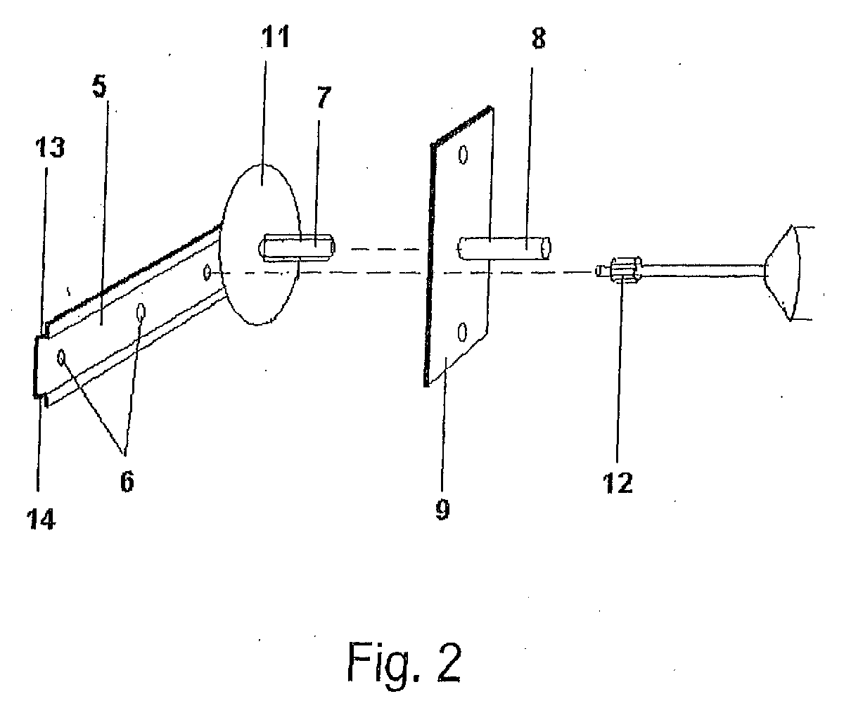
- eine perspektivische Darstellung der erfindungsgemäßen Vorrichtung zur Befestigung von Bauelementen an Bauwerken.
- Fig. 1
- A section through a component with the device according to the invention for attachment to a building,
- Fig. 2
- a perspective view of the device according to the invention for attachment of components to buildings.
In Fig. 1 dargestellt ist eine Schnittansicht durch die Wand 1 eines Bauwerkes,
bei der es sich um ein Mauerwerk, eine Betonwand, einen Balken oder
dergleichen handeln kann. An der Wandaußenseite vorgesetzt ist eine Schicht
Dämmmaterials 2, die der Wärmeisolierung dient.1 shows a sectional view through the wall 1 of a building,
if it is a masonry, a concrete wall, a beam or
can act like that. On the outside of the wall, there is a
Der Dämmschicht 2 vorgesetzt ist wiederum ein äußeres Verblendmauerwerk 3,
so dass sich insgesamt ein mehrschaliges Mauerwerk ergibt. Zur Vermeidung
von Kältebrücken sind Bauelemente 4, insbesondere Fenster und Türen, in der
Ebene der Dämmschicht 2 zu montieren.The
Die Vorrichtung zur Befestigung des Bauelementes 4 wird gebildet durch ein
Montageblech 5, dessen freies Ende mit dem Bauwerk verbindbar ist, dadurch
dass durch Durchbrüche 6 Schrauben oder dergleichen führbar sind, um das
freie Ende des Montagebleches 5 mit der Wand 1 des Bauwerkes fest zu
verbinden. The device for fastening the
Zur Erhöhung der Steifigkeit weist das Montageblech 5 abgewinkelte Kanten 13,
14 auf. Alternativ oder kommutativ können Verstärkungen oder Versteifungen
vorgesehen sein.To increase the rigidity, the
Das Befestigungsmittel weist an seinem dem Bauelement 4 zugewandten Ende
eine in Richtung des Bauelementes orientierte, in der Montageebene des
Bauelementes 4 liegende Gewindestange 7 auf. Diese Gewindestange 7 ist in
eine Gewindehülse 8 einschraubbar. Die Gewindehülse 8 wird mittels eines an
dem Bauelement 4 anschraubbaren Montageblech 9, mit dem die Gewindehülse
8 fest verbunden ist, in eine entsprechende Ausnehmung 10 in dem Bauelement
4 eingesetzt und fixiert, das heißt insbesondere gegen Verdrehung gesichert.The fastening means has at its the
Mittels der in die Gewindehülse 8 einschraubbaren Gewindestange 7 kann der
Abstand zwischen dem Montageblech 5 und dem Bauelement 4 variiert und
eingestellt werden.By means of the screwed into the threaded
Die Gewindestange 7 ist drehbar in dem Montageblech 5 gelagert. Zur Drehung
der Gewindestange 7 und somit der Einstellung des Abstandes zwischen
Montageblech 5 und Bauelement 4 ist am Fuß der Gewindestange 7 eine
kreisförmige Scheibe 11 angeordnet, die auf ihrem Umfang einen Zahnkranz
aufweist. Mittels eines entsprechenden Werkzeuges 12 (Ritzel), das in den
Zahnkranz der Scheibe 11 eingreifen kann, kann die Gewindestange 7 gedreht
und somit der Abstand zwischen Montageblech 5 und Bauelement 4 eingestellt
werden. Das Einstellwerkzeug 12 kann dabei mittels einer Rechts-/Linkslauf-Bohrmaschine
betätigt werden.The threaded
Mit rund um das zu fixierende Bauelement 4 angeordneten erfindungsgemäßen
Vorrichtungen ist es somit leicht möglich, das Bauelement 4 in dem Bauwerk
auszurichten und stabil und dauerhaft zu fixieren. Die erfindungsgemäße
Vorrichtung ist dabei unabhängig von dem Material des Bauelements, das heißt
beispielsweise sowohl bei Holz- und Kunststofffenstern und -Türen als auch bei
Aluminiumprofilen sowie Haustüren aller Art einsetzbar. With arranged around the component to be fixed 4 according to the invention
Devices, it is thus easily possible, the
In dem dargestellten Ausführungsbeispiel ist die Gewindehülse 8 fest mit einem
Montageblech 9 verbunden und wird dadurch fest mit dem Bauelement 4
verbunden, dass das Montageblech 9 an das Bauelement 4 angeschraubt wird.In the illustrated embodiment, the threaded
Nachdem das Bauelement rund um mit erfindungsgemäßen Befestigungsvorrichtungen ausgerichtet und befestigt ist, können die verbleibenden Fugen zwischen dem Bauelement und dem Bauwerk mittels herkömmlicher Techniken verschlossen und abgedichtet werden.After the device around with inventive Fasteners aligned and attached, the remaining joints between the component and the structure by means of closed and sealed by conventional techniques.
In einer nicht dargestellten Alternative kann die erfindungsgemäße Vorrichtung auch der Gestalt ausgebildet sein, dass das Befestigungsmittel an seinem dem Bauelement zugewandten Ende eine in Richtung des Bauelementes orientierte, in der Montageebene des Bauelementes liegende Gewindestange oder Gewindehülse aufweist, wobei ein entsprechendes Gegenstück das Bauelement durchgreift und das Bauelement somit ausrichtbar und fixierbar ist.In an alternative, not shown, the inventive device be formed also the shape that the fastener at his the Component-facing end oriented in the direction of the component, in the mounting plane of the component lying threaded rod or Threaded sleeve, wherein a corresponding counterpart the component passes through and the component is thus alignable and fixable.
Claims (10)
Priority Applications (1)
| Application Number | Priority Date | Filing Date | Title |
|---|---|---|---|
| PL04027493T PL1544400T3 (en) | 2003-12-15 | 2004-11-19 | Fixing device |
Applications Claiming Priority (4)
| Application Number | Priority Date | Filing Date | Title |
|---|---|---|---|
| DE10358947 | 2003-12-15 | ||
| DE10358947 | 2003-12-15 | ||
| DE102004051440 | 2004-10-22 | ||
| DE102004051440A DE102004051440A1 (en) | 2003-12-15 | 2004-10-22 | fastening device |
Publications (3)
| Publication Number | Publication Date |
|---|---|
| EP1544400A2 true EP1544400A2 (en) | 2005-06-22 |
| EP1544400A3 EP1544400A3 (en) | 2006-09-20 |
| EP1544400B1 EP1544400B1 (en) | 2008-09-03 |
Family
ID=34524078
Family Applications (1)
| Application Number | Title | Priority Date | Filing Date |
|---|---|---|---|
| EP04027493A Expired - Lifetime EP1544400B1 (en) | 2003-12-15 | 2004-11-19 | Fixing device |
Country Status (2)
| Country | Link |
|---|---|
| EP (1) | EP1544400B1 (en) |
| PL (1) | PL1544400T3 (en) |
Cited By (1)
| Publication number | Priority date | Publication date | Assignee | Title |
|---|---|---|---|---|
| LT5984B (en) | 2013-02-14 | 2013-12-27 | UŽDAROJI AKCINĖ BENDROVĖ "Good Service Solution" | Bracket device having an adjustable support screw element for securing windows and doors in an insulation layer |
Family Cites Families (6)
| Publication number | Priority date | Publication date | Assignee | Title |
|---|---|---|---|---|
| GB634899A (en) * | 1947-05-20 | 1950-03-29 | Gen Bronze Corp | Improvements in or relating to window frame constructions |
| DE8807747U1 (en) * | 1988-06-15 | 1988-08-18 | Zehnpfennig, Josef, 5010 Bergheim | holder |
| DE9415548U1 (en) * | 1994-09-26 | 1994-11-17 | Bayer Feinmechanik, 85579 Neubiberg | Spacer for setting a variable distance |
| DE29705785U1 (en) * | 1997-04-02 | 1997-05-22 | Kockler, Rita, 66763 Dillingen | Device for fastening window or door frames to the masonry |
| EP0945577B2 (en) * | 1998-03-23 | 2010-03-24 | SFS intec Holding AG | Use of profile bar to support door or window frames |
| DE20118506U1 (en) * | 2001-10-31 | 2002-01-31 | Schlutz, Günter, 34311 Naumburg | Frame for a door or window sash |
-
2004
- 2004-11-19 EP EP04027493A patent/EP1544400B1/en not_active Expired - Lifetime
- 2004-11-19 PL PL04027493T patent/PL1544400T3/en unknown
Cited By (1)
| Publication number | Priority date | Publication date | Assignee | Title |
|---|---|---|---|---|
| LT5984B (en) | 2013-02-14 | 2013-12-27 | UŽDAROJI AKCINĖ BENDROVĖ "Good Service Solution" | Bracket device having an adjustable support screw element for securing windows and doors in an insulation layer |
Also Published As
| Publication number | Publication date |
|---|---|
| EP1544400A3 (en) | 2006-09-20 |
| PL1544400T3 (en) | 2009-04-30 |
| EP1544400B1 (en) | 2008-09-03 |
Similar Documents
| Publication | Publication Date | Title |
|---|---|---|
| EP0945577B2 (en) | Use of profile bar to support door or window frames | |
| EP0921252B1 (en) | Fastening element for distance-fixing of slats, profiles, panels, or the like on a solid base | |
| DE102017002170A1 (en) | Spacers and fasteners for parts to be fastened to buildings through a facade | |
| EP1500768B1 (en) | Support and fixing device for door or window frames at the edge of wall openings | |
| DE2061901A1 (en) | Clamping device for plastic frames for windows and doors, in particular made of hard PVC | |
| DE19948543A1 (en) | Method for aligning window frame in wall opening uses self threaded aligning bolts with external self tapping thread fitted through the frame and onto wall supports | |
| DE3045474C2 (en) | ||
| EP1544400B1 (en) | Fixing device | |
| EP3995661B1 (en) | Window or door frame with sliding elements and gluing thereof to masonry and mounting method for same | |
| EP3502398B1 (en) | Burglar-proof door, connection device contained therein and a construction method | |
| DE102004051440A1 (en) | fastening device | |
| DE102023111184A1 (en) | Reinforcement for an aerated concrete beam, aerated concrete beam, use of an aerated concrete beam, method for reinforcing an aerated concrete beam and use of a reinforcement | |
| DE19537000C1 (en) | Method for the adjustable fastening of slats, rails, plates or the like to a solid surface and fastening element for carrying out the method | |
| EP3091167B1 (en) | Fastening element for attaching a window frame to a ceiling of a structure, associated structure and method for fixing a frame of a window to a ceiling | |
| DE102019114492A1 (en) | Fixing system with power distribution | |
| EP4124761A1 (en) | Verankerung eines bauwerkes an einem ortsfesten untergrund | |
| DE10301320B4 (en) | sealing | |
| DE102010020278A1 (en) | Device for providing an attachment point to a profile element | |
| DE102010027368B4 (en) | Device for the corner attachment of a soffit plate | |
| DE102016204383A1 (en) | An element | |
| WO1997041325A1 (en) | Adjusting device for a component, e.g. a window or door frame, to be fitted in an aperture in a building | |
| EP4102085B1 (en) | Fastening system for mounting plate-shaped elements | |
| DE20005167U1 (en) | Sealing element | |
| DE202006000604U1 (en) | Spacer for profiles of mounting plate has foot sleeve which can be fastened at building structure and profile consists of connectable distance rod which is lockable into foot sleeve in axial direction | |
| DE19706939A1 (en) | Coping support for door or window lintel |
Legal Events
| Date | Code | Title | Description |
|---|---|---|---|
| PUAI | Public reference made under article 153(3) epc to a published international application that has entered the european phase |
Free format text: ORIGINAL CODE: 0009012 |
|
| AK | Designated contracting states |
Kind code of ref document: A2 Designated state(s): AT BE BG CH CY CZ DE DK EE ES FI FR GB GR HU IE IS IT LI LU MC NL PL PT RO SE SI SK TR |
|
| AX | Request for extension of the european patent |
Extension state: AL HR LT LV MK YU |
|
| PUAL | Search report despatched |
Free format text: ORIGINAL CODE: 0009013 |
|
| AK | Designated contracting states |
Kind code of ref document: A3 Designated state(s): AT BE BG CH CY CZ DE DK EE ES FI FR GB GR HU IE IS IT LI LU MC NL PL PT RO SE SI SK TR |
|
| AX | Request for extension of the european patent |
Extension state: AL HR LT LV MK YU |
|
| RAP1 | Party data changed (applicant data changed or rights of an application transferred) |
Owner name: SCHREINEREI ZIMMEREI LOTHAR KLEINBYLEN |
|
| RIN1 | Information on inventor provided before grant (corrected) |
Inventor name: KLEINBYLEN, LOTHAR |
|
| 17P | Request for examination filed |
Effective date: 20070129 |
|
| AKX | Designation fees paid |
Designated state(s): AT BE BG CH CY CZ DE DK EE ES FI FR GB GR HU IE IS IT LI LU MC NL PL PT RO SE SI SK TR |
|
| 17Q | First examination report despatched |
Effective date: 20071221 |
|
| GRAP | Despatch of communication of intention to grant a patent |
Free format text: ORIGINAL CODE: EPIDOSNIGR1 |
|
| GRAS | Grant fee paid |
Free format text: ORIGINAL CODE: EPIDOSNIGR3 |
|
| GRAA | (expected) grant |
Free format text: ORIGINAL CODE: 0009210 |
|
| AK | Designated contracting states |
Kind code of ref document: B1 Designated state(s): AT BE BG CH CY CZ DE DK EE ES FI FR GB GR HU IE IS IT LI LU MC NL PL PT RO SE SI SK TR |
|
| REG | Reference to a national code |
Ref country code: GB Ref legal event code: FG4D Free format text: NOT ENGLISH |
|
| REG | Reference to a national code |
Ref country code: CH Ref legal event code: EP |
|
| REG | Reference to a national code |
Ref country code: IE Ref legal event code: FG4D Free format text: LANGUAGE OF EP DOCUMENT: GERMAN |
|
| REF | Corresponds to: |
Ref document number: 502004007974 Country of ref document: DE Date of ref document: 20081016 Kind code of ref document: P |
|
| REG | Reference to a national code |
Ref country code: SE Ref legal event code: TRGR |
|
| PG25 | Lapsed in a contracting state [announced via postgrant information from national office to epo] |
Ref country code: ES Free format text: LAPSE BECAUSE OF FAILURE TO SUBMIT A TRANSLATION OF THE DESCRIPTION OR TO PAY THE FEE WITHIN THE PRESCRIBED TIME-LIMIT Effective date: 20081214 |
|
| PG25 | Lapsed in a contracting state [announced via postgrant information from national office to epo] |
Ref country code: SI Free format text: LAPSE BECAUSE OF FAILURE TO SUBMIT A TRANSLATION OF THE DESCRIPTION OR TO PAY THE FEE WITHIN THE PRESCRIBED TIME-LIMIT Effective date: 20080903 Ref country code: FI Free format text: LAPSE BECAUSE OF FAILURE TO SUBMIT A TRANSLATION OF THE DESCRIPTION OR TO PAY THE FEE WITHIN THE PRESCRIBED TIME-LIMIT Effective date: 20080903 |
|
| PG25 | Lapsed in a contracting state [announced via postgrant information from national office to epo] |
Ref country code: BG Free format text: LAPSE BECAUSE OF FAILURE TO SUBMIT A TRANSLATION OF THE DESCRIPTION OR TO PAY THE FEE WITHIN THE PRESCRIBED TIME-LIMIT Effective date: 20081203 |
|
| REG | Reference to a national code |
Ref country code: PL Ref legal event code: T3 |
|
| PG25 | Lapsed in a contracting state [announced via postgrant information from national office to epo] |
Ref country code: RO Free format text: LAPSE BECAUSE OF FAILURE TO SUBMIT A TRANSLATION OF THE DESCRIPTION OR TO PAY THE FEE WITHIN THE PRESCRIBED TIME-LIMIT Effective date: 20080903 Ref country code: PT Free format text: LAPSE BECAUSE OF FAILURE TO SUBMIT A TRANSLATION OF THE DESCRIPTION OR TO PAY THE FEE WITHIN THE PRESCRIBED TIME-LIMIT Effective date: 20090203 Ref country code: SK Free format text: LAPSE BECAUSE OF FAILURE TO SUBMIT A TRANSLATION OF THE DESCRIPTION OR TO PAY THE FEE WITHIN THE PRESCRIBED TIME-LIMIT Effective date: 20080903 Ref country code: CZ Free format text: LAPSE BECAUSE OF FAILURE TO SUBMIT A TRANSLATION OF THE DESCRIPTION OR TO PAY THE FEE WITHIN THE PRESCRIBED TIME-LIMIT Effective date: 20080903 Ref country code: IS Free format text: LAPSE BECAUSE OF FAILURE TO SUBMIT A TRANSLATION OF THE DESCRIPTION OR TO PAY THE FEE WITHIN THE PRESCRIBED TIME-LIMIT Effective date: 20090103 |
|
| PG25 | Lapsed in a contracting state [announced via postgrant information from national office to epo] |
Ref country code: MC Free format text: LAPSE BECAUSE OF NON-PAYMENT OF DUE FEES Effective date: 20081130 |
|
| REG | Reference to a national code |
Ref country code: CH Ref legal event code: PL |
|
| PLBE | No opposition filed within time limit |
Free format text: ORIGINAL CODE: 0009261 |
|
| STAA | Information on the status of an ep patent application or granted ep patent |
Free format text: STATUS: NO OPPOSITION FILED WITHIN TIME LIMIT |
|
| PG25 | Lapsed in a contracting state [announced via postgrant information from national office to epo] |
Ref country code: DK Free format text: LAPSE BECAUSE OF FAILURE TO SUBMIT A TRANSLATION OF THE DESCRIPTION OR TO PAY THE FEE WITHIN THE PRESCRIBED TIME-LIMIT Effective date: 20080903 Ref country code: EE Free format text: LAPSE BECAUSE OF FAILURE TO SUBMIT A TRANSLATION OF THE DESCRIPTION OR TO PAY THE FEE WITHIN THE PRESCRIBED TIME-LIMIT Effective date: 20080903 |
|
| 26N | No opposition filed |
Effective date: 20090604 |
|
| PG25 | Lapsed in a contracting state [announced via postgrant information from national office to epo] |
Ref country code: CH Free format text: LAPSE BECAUSE OF NON-PAYMENT OF DUE FEES Effective date: 20081130 Ref country code: LI Free format text: LAPSE BECAUSE OF NON-PAYMENT OF DUE FEES Effective date: 20081130 |
|
| REG | Reference to a national code |
Ref country code: HU Ref legal event code: AG4A Ref document number: E006671 Country of ref document: HU |
|
| PG25 | Lapsed in a contracting state [announced via postgrant information from national office to epo] |
Ref country code: CY Free format text: LAPSE BECAUSE OF FAILURE TO SUBMIT A TRANSLATION OF THE DESCRIPTION OR TO PAY THE FEE WITHIN THE PRESCRIBED TIME-LIMIT Effective date: 20080903 |
|
| PG25 | Lapsed in a contracting state [announced via postgrant information from national office to epo] |
Ref country code: TR Free format text: LAPSE BECAUSE OF FAILURE TO SUBMIT A TRANSLATION OF THE DESCRIPTION OR TO PAY THE FEE WITHIN THE PRESCRIBED TIME-LIMIT Effective date: 20080903 |
|
| PG25 | Lapsed in a contracting state [announced via postgrant information from national office to epo] |
Ref country code: GR Free format text: LAPSE BECAUSE OF FAILURE TO SUBMIT A TRANSLATION OF THE DESCRIPTION OR TO PAY THE FEE WITHIN THE PRESCRIBED TIME-LIMIT Effective date: 20081204 |
|
| PGFP | Annual fee paid to national office [announced via postgrant information from national office to epo] |
Ref country code: HU Payment date: 20111118 Year of fee payment: 8 |
|
| PGFP | Annual fee paid to national office [announced via postgrant information from national office to epo] |
Ref country code: LU Payment date: 20121126 Year of fee payment: 9 |
|
| PGFP | Annual fee paid to national office [announced via postgrant information from national office to epo] |
Ref country code: IE Payment date: 20121120 Year of fee payment: 9 |
|
| PGFP | Annual fee paid to national office [announced via postgrant information from national office to epo] |
Ref country code: SE Payment date: 20121122 Year of fee payment: 9 Ref country code: IT Payment date: 20121123 Year of fee payment: 9 Ref country code: BE Payment date: 20121129 Year of fee payment: 9 Ref country code: PL Payment date: 20121107 Year of fee payment: 9 Ref country code: GB Payment date: 20121122 Year of fee payment: 9 |
|
| PGFP | Annual fee paid to national office [announced via postgrant information from national office to epo] |
Ref country code: NL Payment date: 20121122 Year of fee payment: 9 Ref country code: FR Payment date: 20121217 Year of fee payment: 9 Ref country code: AT Payment date: 20121122 Year of fee payment: 9 |
|
| PG25 | Lapsed in a contracting state [announced via postgrant information from national office to epo] |
Ref country code: HU Free format text: LAPSE BECAUSE OF NON-PAYMENT OF DUE FEES Effective date: 20121120 |
|
| BERE | Be: lapsed |
Owner name: SCHREINEREI ZIMMEREI LOTHAR KLEINBYLEN Effective date: 20131130 |
|
| REG | Reference to a national code |
Ref country code: NL Ref legal event code: V1 Effective date: 20140601 |
|
| REG | Reference to a national code |
Ref country code: SE Ref legal event code: EUG |
|
| REG | Reference to a national code |
Ref country code: AT Ref legal event code: MM01 Ref document number: 407281 Country of ref document: AT Kind code of ref document: T Effective date: 20131119 |
|
| GBPC | Gb: european patent ceased through non-payment of renewal fee |
Effective date: 20131119 |
|
| REG | Reference to a national code |
Ref country code: FR Ref legal event code: ST Effective date: 20140731 |
|
| REG | Reference to a national code |
Ref country code: IE Ref legal event code: MM4A |
|
| PG25 | Lapsed in a contracting state [announced via postgrant information from national office to epo] |
Ref country code: SE Free format text: LAPSE BECAUSE OF NON-PAYMENT OF DUE FEES Effective date: 20131120 Ref country code: AT Free format text: LAPSE BECAUSE OF NON-PAYMENT OF DUE FEES Effective date: 20131119 Ref country code: IT Free format text: LAPSE BECAUSE OF NON-PAYMENT OF DUE FEES Effective date: 20131119 Ref country code: NL Free format text: LAPSE BECAUSE OF NON-PAYMENT OF DUE FEES Effective date: 20140601 |
|
| PG25 | Lapsed in a contracting state [announced via postgrant information from national office to epo] |
Ref country code: BE Free format text: LAPSE BECAUSE OF NON-PAYMENT OF DUE FEES Effective date: 20131130 |
|
| PG25 | Lapsed in a contracting state [announced via postgrant information from national office to epo] |
Ref country code: IE Free format text: LAPSE BECAUSE OF NON-PAYMENT OF DUE FEES Effective date: 20131119 |
|
| PG25 | Lapsed in a contracting state [announced via postgrant information from national office to epo] |
Ref country code: GB Free format text: LAPSE BECAUSE OF NON-PAYMENT OF DUE FEES Effective date: 20131119 Ref country code: FR Free format text: LAPSE BECAUSE OF NON-PAYMENT OF DUE FEES Effective date: 20131202 |
|
| PG25 | Lapsed in a contracting state [announced via postgrant information from national office to epo] |
Ref country code: PL Free format text: LAPSE BECAUSE OF NON-PAYMENT OF DUE FEES Effective date: 20131119 |
|
| REG | Reference to a national code |
Ref country code: PL Ref legal event code: LAPE |
|
| PG25 | Lapsed in a contracting state [announced via postgrant information from national office to epo] |
Ref country code: LU Free format text: LAPSE BECAUSE OF NON-PAYMENT OF DUE FEES Effective date: 20131119 |
|
| PGFP | Annual fee paid to national office [announced via postgrant information from national office to epo] |
Ref country code: DE Payment date: 20161125 Year of fee payment: 13 |
|
| REG | Reference to a national code |
Ref country code: DE Ref legal event code: R119 Ref document number: 502004007974 Country of ref document: DE |
|
| PG25 | Lapsed in a contracting state [announced via postgrant information from national office to epo] |
Ref country code: DE Free format text: LAPSE BECAUSE OF NON-PAYMENT OF DUE FEES Effective date: 20180602 |