EP0945577B2 - Use of profile bar to support door or window frames - Google Patents
Use of profile bar to support door or window frames Download PDFInfo
- Publication number
- EP0945577B2 EP0945577B2 EP99104333A EP99104333A EP0945577B2 EP 0945577 B2 EP0945577 B2 EP 0945577B2 EP 99104333 A EP99104333 A EP 99104333A EP 99104333 A EP99104333 A EP 99104333A EP 0945577 B2 EP0945577 B2 EP 0945577B2
- Authority
- EP
- European Patent Office
- Prior art keywords
- rail
- profiled
- wall
- use according
- window
- Prior art date
- Legal status (The legal status is an assumption and is not a legal conclusion. Google has not performed a legal analysis and makes no representation as to the accuracy of the status listed.)
- Expired - Lifetime
Links
Images

Classifications
-
- E—FIXED CONSTRUCTIONS
- E06—DOORS, WINDOWS, SHUTTERS, OR ROLLER BLINDS IN GENERAL; LADDERS
- E06B—FIXED OR MOVABLE CLOSURES FOR OPENINGS IN BUILDINGS, VEHICLES, FENCES OR LIKE ENCLOSURES IN GENERAL, e.g. DOORS, WINDOWS, BLINDS, GATES
- E06B1/00—Border constructions of openings in walls, floors, or ceilings; Frames to be rigidly mounted in such openings
- E06B1/003—Cavity wall closers; Fastening door or window frames in cavity walls
-
- E—FIXED CONSTRUCTIONS
- E06—DOORS, WINDOWS, SHUTTERS, OR ROLLER BLINDS IN GENERAL; LADDERS
- E06B—FIXED OR MOVABLE CLOSURES FOR OPENINGS IN BUILDINGS, VEHICLES, FENCES OR LIKE ENCLOSURES IN GENERAL, e.g. DOORS, WINDOWS, BLINDS, GATES
- E06B1/00—Border constructions of openings in walls, floors, or ceilings; Frames to be rigidly mounted in such openings
- E06B1/56—Fastening frames to the border of openings or to similar contiguous frames
- E06B1/60—Fastening frames to the border of openings or to similar contiguous frames by mechanical means, e.g. anchoring means
- E06B1/6015—Anchoring means
-
- E—FIXED CONSTRUCTIONS
- E06—DOORS, WINDOWS, SHUTTERS, OR ROLLER BLINDS IN GENERAL; LADDERS
- E06B—FIXED OR MOVABLE CLOSURES FOR OPENINGS IN BUILDINGS, VEHICLES, FENCES OR LIKE ENCLOSURES IN GENERAL, e.g. DOORS, WINDOWS, BLINDS, GATES
- E06B1/00—Border constructions of openings in walls, floors, or ceilings; Frames to be rigidly mounted in such openings
- E06B1/56—Fastening frames to the border of openings or to similar contiguous frames
- E06B1/60—Fastening frames to the border of openings or to similar contiguous frames by mechanical means, e.g. anchoring means
- E06B1/6069—Separate spacer means acting exclusively in the plane of the opening; Shims; Wedges; Tightening of a complete frame inside a wall opening
- E06B1/6076—Separate spacer means acting exclusively in the plane of the opening; Shims; Wedges; Tightening of a complete frame inside a wall opening of screw-type
Definitions
- the invention relates to the use of a rail according to the preamble of patent claim 1.
- a mounting of window or door frame is often required directly in the range of sections of non-supporting material.
- plate elements made of wood have hitherto been placed on at least the lower boundary of a wall opening. Then the door or window frame is adjusted in height by means of wedges or additional backing material.
- additional adjustment options are no longer possible with such a construction.
- a profile element which may be a plate or simply a flat iron, which (s) can be bent in a desired manner, ie z. B. to a kind of angle rail.
- the profile element has except a slot and a round hole formed on the profile element or threaded bushing, which has a hole and is received in a recess of an adjusting element. The profile element thus serves together with the projecting threaded bushing for supporting the adjusting element in a specific position.
- a profile rail as used in the use of the aforementioned type, is from the document FR-A-2 725 263 known.
- a supported by this rail window or door frame is adjustable with a sliding on the rail adjustment in the longitudinal direction of the rail.
- the present invention has now taken on the task of designing a rail so that when using the type mentioned in the window or door frame can be supported even in arrangement directly in the field of non-sustainable material variable.
- the possibility is created to bridge a non-load-bearing section at the boundary of a wall opening in a wall or freely cantilever to arrange from one side.
- the provided during use rail can be firmly connected to a wall section of load-bearing material, so that the rail thanks to the rigid training even if it protrudes freely cantilevered in the wall portion of resilient, non-load-bearing material, for a sufficient support of a window - Or door frame can be used.
- such a rail can be formed of a relatively small cross-section, so that the profile rail in the resting on the boundary of the wall opening condition for a subsequent application of e.g. End strips, a plaster, by window sills or thresholds, etc. does not obstruct the way.
- the position of the adjusting element with respect to the rail is variable and thus the position of the window or door frame to be fastened with respect to the masonry is variable.
- the adjusting element is brought into engagement with one or the other of the openings with a free end.
- the profile rail is designed as a hollow profile element.
- a relatively large bending stiffness of the rail can be achieved, even if a free end of the same freely cantilever in the region of a wall portion of non-load-bearing material to support a window or door frame.
- a sufficient bending stiffness of a rail can also be achieved if the rail is formed as a cross-section approximately U-, C- or I-shaped profile element.
- the oblong hole By means of the oblong hole provided according to the invention, it is possible to fasten the rigid profile rail in the region of the oblong hole to a wall section of load-bearing material, e.g. a screw is only tightened so far that the rail can still move in the longitudinal direction. If the window or door frame is supported on the adjusting element on the rigid profile rail, this can be moved in a simple manner in a certain area, which is limited to the length of the elongated holes, transversely to its plane.
- the fastener is tightened only after the final setting of the door or window frame, so that the rigid profile rail can not move. In a loose state of the rail but not only given the opportunity to move them still in the longitudinal direction, but the rail can also pivot in this state about the axis of the fastener, thereby moving a door or window frame in the plane is possible.
- a particular variant of use provides that the profile rail formed in cross-section as a C-shaped profile element at the free edge regions with oppositely directed inwardly projecting webs to form bilateral guide grooves is.
- a particular bending stiffness is achieved, on the other hand, there are more use variants.
- an advantageous embodiment of the use is characterized by a in the rail or in guide grooves of the same form-fitting retractable retaining rail.
- the rail is designed as a hollow profile element or has corresponding guide grooves.
- additional mounting options can be created. For example, this can only be an extension of the rigid profile rail, which can then be telescopically extendable, so to speak. It is basically possible to perform the support rail only from a stable sheet or as a rigid element. Therefore, it is conceivable that the retaining rail is designed as a hollow or solid profile or as a flat profile. Depending on the purpose and art different versions are provided.
- the holding rail has two sections which are approximately at right angles to one another, wherein one section is insertable into the profile rail and the other section is designed for attachment to a wall section adjoining the wall opening.
- a kind of angle bracket can be formed, with which detects the one end of the rigid profile rail and pressed against the boundary of the wall opening and the other section can be set, for example, on the inner boundary of a wall with a fastener.
- the wall sections are formed of load-bearing material, for example, of bricks with vertically continuous channels. In this case, an attachment across the continuous channels is much easier and more effective possible.
- retractable retaining rails is also possible to connect the rigid profile rail and the support rail mutually immovably, for example via a locking screw with each other, as soon as the proper alignment of the window or door frame is done.
- these are suitable for inserting fastening elements with one or more holes, e.g. also designed as slots, is provided.
- these holes can be used for connection between the rail and the support rail, on the other hand, this creates multiple mounting options on the corresponding wall section.
- a further variant of use provides that the retaining rail is held captive on the rail and slidably guided in this direction in the longitudinal direction and lockable. With such a configuration, it is possible to bring holding rail and rail as a unit to the site. Especially for precise alignment of the device used in the inventive use, it makes sense if these two parts are captively connected to each other, but can be mutually adjusted in a relatively large area. This also makes it possible in a simple manner, the retaining rail already firmly connected to the boundary of a wall opening, with a displacement of the rail relative to the retaining rail is still feasible. The window or door frame to be fastened can thus be optimally adjusted.
- an advantageous embodiment of this form of use lies in the fact that the retaining rail has at its one active with the profile rail section an elongated hole through which engages a screw in a threaded bore on the rail.
- an adjustment in a relatively large displacement range is possible through the slot, on the other hand can be prevented by simply setting the guided through the slot screw a further relative displacement between support rail and rail.
- a multi-layer structure in which case, for example, a masonry 2, an insulating layer 3 and an outer lining 4 are provided.
- the outer lining 4 can also be designed as additional masonry.
- the thus constructed wall 1 is provided with a corresponding wall opening, in which a window frame 5 or a door frame to be used.
- the boundary 6 of the wall opening is from the top of the masonry 2, the insulating layer 3 and optionally an outer lining 4 formed.
- a rigid profile rail 7 which on the one hand has holes for the passage of fasteners 8 for use in wall sections of load-bearing material and on the other hand openings for engagement or support of an adjusting element 9 for the adjustable support of a window frame 5.
- openings can be provided, in which a free end of the adjusting element 9 can engage positively.
- a direct positive and non-positive connection between such adjustment element 9 and the rail 7 is possible. In such a case, however, the rail 7 would have to be delivered to the construction site already provided with the adjusting element 9.
- the Fig. 4 taken where a transverse tab 10 is provided at the lower end of an adjusting element 9, which is held displaceably guided in a particular embodiment of the rail 7. Since this is not about the construction of the adjusting element 9, will not be discussed in detail on its function.
- the profile rail is designed as a cross-sectionally C-shaped profile element. It is quite conceivable to design the profile rail as a hollow profile element or, for example, as a profile element which is approximately U-shaped or I-shaped in cross-section. For an additional adjustment of the rail 7 are provided in these slots 11 through which the fastener 8 is used.
- the profile rail 7 is formed in the embodiment shown as a substantially cross-sectionally C-shaped profile element. Here are at the free edge regions of the rail 7 against each other directed inwardly projecting webs 12 are provided, which form guide grooves 13 at both longitudinal edges of the rail.
- a retaining rail 14 can be positively inserted into the rail 7. Such insertion of a retaining rail 14 is of course also possible if the rail 7 is formed as a hollow profile.
- the retaining rail 14 may be formed as a hollow or solid profile or as a flat profile. Whether the support rail 14 should also be rigid or must or not, is chosen depending on the application.
- the support rail 14 may be formed as a straight-line element and serve in such a case, for example, as an extension of the rail 7.
- the retaining rail 14 has two mutually at approximately right angles to each other sections 15 and 16. The one section 15 is inserted into the rail 7 and the other section 16 is used for attachment to a wall portion adjacent to the wall portion 17.
- Especially with bricks 18 with hollow chambers 19 is an attachment transverse to the hollow chambers 19 much more effective.
- the type of attachment with a fastener 20 can the Fig. 1 and 2 be removed.
- the support rail itself can be provided with one or more holes 21, wherein such holes can be partially designed as slots.
- the holes 21 are used to insert the fastener 20 or for mutual connection between a support rail 14 and a rail 7th
- the profiled rail 7 does not extend on the boundary 6 of the wall opening, i. is supported on the top of the masonry 2, but is arranged cantilevered with a small distance and is attached via the support rail 14 and the corresponding portion 16 on the inner boundary 17 of the wall.
- the rail 7 can also be used as a bridging element, if on both sides of an insulating material layer 3, a corresponding masonry is present.
- the bending-resistant rail has a solid support on both sides and can be connected to a wall section made of load-bearing material.
- the window frame 5 can then be supported at any desired location via an adjusting element 9.
- a retaining rail 14 which can be inserted in a form-locking manner into the rail 7 or in guide grooves thereof is provided.
- this retaining rail may also have two mutually at approximately right angles to each other portions 15, 16, wherein the one portion 15 inserted into the rail 7 and the other portion 16 for attachment to the wall opening adjacent to the wall portion 17 is formed is.
- the support rail 14 is held captive in this embodiment on the rail 7 and thus guided in the longitudinal direction thereof slidably, but with respect to this detectable.
- the illustrated embodiment provides that the retaining rail 14 at its one with the rail 7 in operative connection section 15 has a slot 22.
- the rail 7 has a threaded hole 7, wherein a plurality of spaced successive threaded holes can be provided.
- Through the slot 22 through a screw 23 is inserted into a threaded bore on the rail 7.
- the screw 23 is not tightened from the outset, so that the retaining rail 14 and the rail 7 remain relatively displaceable until the final position is fixed. Subsequently, the screw 23 can be tightened in a simple manner, so that support rail 14 and rail 7 are mutually determined.
- the rail 7 can be made as a metal element or plastic.
- plastic elements such as glass fiber reinforced plastic elements, proves to be advantageous.
Abstract
Description
Die Erfindung betrifft die Verwendung einer Profilschiene nach dem Oberbegriff des Patentanspruchs 1.The invention relates to the use of a rail according to the preamble of
Bei Wandöffnungen in Wänden, z.B. einem Mehrschalenmauerwerk, wird vielfach eine Montage von Fenster- oder Türrahmen unmittelbar im Bereich von Abschnitten aus nicht tragendem Material verlangt. Um diese Abschnitte aus nicht tragendem Material zu überbrücken, werden bisher zumindest an der unteren Begrenzung einer Wandöffnung Plattenelemente aus Holz aufgelegt. Anschließend wird der Tür- oder Fensterrahmen mittels Keilen oder zusätzlichem Unterlegmaterial in der Höhe einjustiert. Zusätzliche Verstellmöglichkeiten sind bei einer solchen Konstruktion jedoch nicht mehr möglich.For wall openings in walls, e.g. a multi-shell masonry, a mounting of window or door frame is often required directly in the range of sections of non-supporting material. In order to bridge these sections of non-load-bearing material, plate elements made of wood have hitherto been placed on at least the lower boundary of a wall opening. Then the door or window frame is adjusted in height by means of wedges or additional backing material. However, additional adjustment options are no longer possible with such a construction.
Zwar sind einige Ausführungsvarianten von zur Abstützung eines Fenster- oder Türrahmens geeigneten Verstellelementen bekannt, welche jedoch ebenfalls keine Möglichkeit der Abstützung unmittelbar auf einem Wandabschnitt aus nicht tragfähigem Material bieten. Bei solchen Konstruktionen handelt es sich zumeist um eine Art Schlauder, welche jedoch lediglich dazu dient, einen Fenster- oder Türrahmen quer zu dessen Ebene unverschiebbar mit der Begrenzung einer Wandöffnung zu verbinden. Derartige Ausführungen sind beispielsweise aus der
Das vorstehend letztgenannte Dokument betrifft ein Verfahren und eine Einrichtung zum dauerhaften einstellbaren Verbinden von zwei Strukturelementen wie einem Tür- oder Fensterrahmen einerseits und einer umgebenden stationären Gebäudestruktur andererseits, die gegeneinander versetzt angeordnet sind. Für diese Verbindung wird ein Profilelement verwendet, das eine Platte oder einfach ein Flacheisen sein kann, welche(s) auf gewünschte Weise gebogen werden kann, also z. B. zu einer Art Winkelschiene. Das Profilelement hat außer einem Langloch und einem runden Loch eine an dem Profilelement angeformte oder angebrachte Gewindebüchse, die ein Loch aufweist und in einer Ausnehmung eines Verstellelements aufgenommen wird. Das Profilelement dient also zusammen mit der vorstehenden Gewindebüchse zum Abstützen des Verstellelements in einer bestimmten Position.The above-mentioned document relates to a method and a device for permanently adjustable connection of two structural elements such as a door or window frame on the one hand and a surrounding stationary building structure on the other hand, which are arranged offset from one another. For this compound, a profile element is used, which may be a plate or simply a flat iron, which (s) can be bent in a desired manner, ie z. B. to a kind of angle rail. The profile element has except a slot and a round hole formed on the profile element or threaded bushing, which has a hole and is received in a recess of an adjusting element. The profile element thus serves together with the projecting threaded bushing for supporting the adjusting element in a specific position.
Eine Profilschiene, wie sie bei der Verwendung der eingangs genannten Art eingesetzt wird, ist aus dem Dokument
Aus dem Dokument
Die vorliegende Erfindung hat sich nun zur Aufgabe gestellt, eine Profilschiene so auszubilden, dass sich bei einer Verwendung der eingangs genannten Art Fenster- oder Türrahmen auch bei Anordnung direkt im Bereich von nicht tragfähigem Material variabler abstützen lassen.The present invention has now taken on the task of designing a rail so that when using the type mentioned in the window or door frame can be supported even in arrangement directly in the field of non-sustainable material variable.
Erfindungsgemäß gelingt dies durch eine Verwendung der eingangs genannten Art mit den Merkmalen des kennzeichnenden Teils des Anspruchs 1.This is achieved by a use of the type mentioned above with the features of the characterizing part of
Durch die Erfindung wird die Möglichkeit geschaffen, einen nicht tragfähigen Abschnitt an der Begrenzung einer Wandöffnung in einer Wand zu überbrücken oder aber frei auskragend von einer Seite her anzuordnen. Die bei der Verwendung vorgesehene Profilschiene kann fest mit einem Wandabschnitt aus tragfähigem Material verbunden werden, so dass die Profilschiene dank der biegesteifen Ausbildung auch dann, wenn sie lediglich frei auskragend in den Wandabschnitt aus nachgiebigem, nicht tragfähigem Material hineinragt, für eine ausreichende Abstützung eines Fenster- oder Türrahmens herangezogen werden kann.By the invention, the possibility is created to bridge a non-load-bearing section at the boundary of a wall opening in a wall or freely cantilever to arrange from one side. The provided during use rail can be firmly connected to a wall section of load-bearing material, so that the rail thanks to the rigid training even if it protrudes freely cantilevered in the wall portion of resilient, non-load-bearing material, for a sufficient support of a window - Or door frame can be used.
Trotz der biegesteifen Ausbildung kann eine derartige Profilschiene aus einem relativ kleinen Querschnitt gebildet sein, so dass die Profilschiene in dem auf der Begrenzung der Wandöffnung aufliegenden Zustand für ein nachträgliches Aufbringen von z.B. Abschlussleisten, eines Verputzes, von Fenstersimsen oder Türschwellen usw. nicht hindernd im Wege steht.Despite the rigid construction, such a rail can be formed of a relatively small cross-section, so that the profile rail in the resting on the boundary of the wall opening condition for a subsequent application of e.g. End strips, a plaster, by window sills or thresholds, etc. does not obstruct the way.
Nicht mehr von Belang ist nunmehr, in welcher konstruktiven Ausgestaltung ein Verstellelement zur einstellbaren Abstützung eines Fenster- oder Türrahmens ausgeführt ist - eine solche einfache, biegesteife Profilschiene kann mit allen Ausführungsvarianten zusammenwirken. Dabei ist es auch möglich, ein Verstellelement z.B. bereits vorab form- und/oder kraftschlüssig oder aber nach der Montage der Profilschiene mit dieser in Wirkverbindung zu bringen.No longer of concern is now in which structural design an adjustment for adjustable support of a window or door frame is executed - such a simple, rigid profile rail can cooperate with all variants. It is also possible to use an adjusting element, e.g. already in advance positively and / or non-positively or bring after assembly of the rail with this in operative connection.
Bei der Verwendung nach Anspruch 1 ist die Lage des Verstellelements bezüglich der Profilschiene variabel und somit ist die Lage des zu befestigenden Fenster- oder Türrahmens bezüglich des Mauerwerks variabel. Erfindungsgemäß wird zum Erreichen dieser Variabilität das Verstellelement mit einem freien Ende mit der einen oder anderen der Öffnungen in Eingriff gebracht.When used according to
Eine Möglichkeit sieht vor, dass die Profilschiene als Hohlprofilelement ausgebildet ist. Dadurch kann eine relativ große Biegesteifigkeit der Profilschiene erzielt werden, und zwar selbst dann, wenn ein freies Ende derselben frei auskragend im Bereich eines Wandabschnittes aus nicht tragfähigem Material einen Fenster- oder Türrahmen abstützen soll. Eine ausreichende Biegesteifigkeit einer Profilschiene kann ebenfalls dann erreicht werden, wenn die Profilschiene als im Querschnitt etwa U-, C- oder I-förmiges Profilelement ausgebildet ist.One possibility provides that the profile rail is designed as a hollow profile element. As a result, a relatively large bending stiffness of the rail can be achieved, even if a free end of the same freely cantilever in the region of a wall portion of non-load-bearing material to support a window or door frame. A sufficient bending stiffness of a rail can also be achieved if the rail is formed as a cross-section approximately U-, C- or I-shaped profile element.
Durch das erfindungsgemäß vorgesehene Langloch besteht die Möglichkeit, die biegesteife Profilschiene im Bereich des Langloches an einem Wandabschnitt aus tragfähigem Material zu befestigen, wobei z.B. eine Schraube nur so weit angezogen wird, dass sich die Profilschiene noch in deren Längsrichtung verschieben lässt. Wenn der Fenster- oder Türrahmen über das Verstellelement auf der biegesteifen Profilschiene abgestützt ist, kann dieser in einfacher Weise in einem bestimmten Bereich, welcher auf die Länge der Langlöcher begrenzt ist, quer zu dessen Ebene bewegt werden. Das Befestigungselement wird erst nach dem endgültigen Einstellen des Tür- oder Fensterrahmens fest angezogen, so dass sich die biegesteife Profilschiene nicht mehr verschieben kann. In einem losen Zustand der Profilschiene ist aber nicht nur die Möglichkeit gegeben, diese noch in deren Längsrichtung verschieben zu können, sondern die Profilschiene kann sich in diesem Zustand ebenfalls um die Achse des Befestigungselementes verschwenken, wodurch ein Verschieben eines Tür- oder Fensterahmens in dessen Ebene möglich ist.By means of the oblong hole provided according to the invention, it is possible to fasten the rigid profile rail in the region of the oblong hole to a wall section of load-bearing material, e.g. a screw is only tightened so far that the rail can still move in the longitudinal direction. If the window or door frame is supported on the adjusting element on the rigid profile rail, this can be moved in a simple manner in a certain area, which is limited to the length of the elongated holes, transversely to its plane. The fastener is tightened only after the final setting of the door or window frame, so that the rigid profile rail can not move. In a loose state of the rail but not only given the opportunity to move them still in the longitudinal direction, but the rail can also pivot in this state about the axis of the fastener, thereby moving a door or window frame in the plane is possible.
Eine besondere Verwendungsvariante sieht vor, dass die im Querschnitt als C-förmiges Profilelement ausgebildete Profilschiene an den freien Randbereichen mit gegeneinander gerichtet nach innen abragenden Stegen zur Bildung von beidseitigen Führungsnuten versehen ist. Damit wird einerseits eine besondere Biegesteifigkeit erzielt, andererseits ergeben sich weitere Einsatzvarianten.A particular variant of use provides that the profile rail formed in cross-section as a C-shaped profile element at the free edge regions with oppositely directed inwardly projecting webs to form bilateral guide grooves is. Thus, on the one hand, a particular bending stiffness is achieved, on the other hand, there are more use variants.
In diesem Zusammenhang ist eine vorteilhafte Ausgestaltung der Verwendung gekennzeichnet durch eine in die Profilschiene oder in Führungsnuten derselben formschlüssig einschiebbare Halteschiene. Eine solche zusätzliche Konstruktion ist dann möglich, wenn die Profilschiene als Hohlprofilelement ausgebildet ist oder aber entsprechende Führungsnuten aufweist. Mittels einer Halteschiene können zusätzliche Befestigungsmöglichkeiten geschaffen werden. Beispielsweise kann dies nur eine Verlängerung der biegesteifen Profilschiene sein, welche dann sozusagen teleskopartig ausziehbar verlängert werden kann. Dabei ist es grundsätzlich möglich, die Halteschiene lediglich aus einem stabilen Flachmaterial oder aber als biegesteifes Element auszuführen. Deshalb ist es denkbar, dass die Halteschiene als Hohl- oder Vollprofil oder aber als Flachprofil ausgeführt ist. Je nach Einsatzzweck und Einsatzart werden verschiedene Ausführungsvarianten vorgesehen.In this context, an advantageous embodiment of the use is characterized by a in the rail or in guide grooves of the same form-fitting retractable retaining rail. Such an additional construction is possible if the rail is designed as a hollow profile element or has corresponding guide grooves. By means of a retaining rail additional mounting options can be created. For example, this can only be an extension of the rigid profile rail, which can then be telescopically extendable, so to speak. It is basically possible to perform the support rail only from a stable sheet or as a rigid element. Therefore, it is conceivable that the retaining rail is designed as a hollow or solid profile or as a flat profile. Depending on the purpose and Einsatzart different versions are provided.
Eine spezielle Verwendungsvariante sieht vor, dass die Halteschiene zwei in einem annähernd rechten Winkel zueinander stehende Abschnitte aufweist, wobei der eine Abschnitt in die Profilschiene einschiebbar und der andere Abschnitt zur Befestigung an einem an die Wandöffnung angrenzenden Wandabschnitt ausgebildet ist. Damit kann eine Art Winkellasche gebildet werden, mit welcher das eine Ende der biegesteifen Profilschiene erfasst und gegen die Begrenzung der Wandöffnung angedrückt und der andere Abschnitt beispielsweise an der Innenbegrenzung einer Wand mit einem Befestigungselement festgelegt werden kann. Eine solche Ausführung ist insbesondere dann von Vorteil, wenn die Wandabschnitte aus tragfähigem Material beispielsweise von Ziegeln mit vertikal durchgehenden Kanälen gebildet sind. Diesfalls ist eine Befestigung quer zu den durchlaufenden Kanälen wesentlich einfacher und wirksamer möglich.A special variant of use provides that the holding rail has two sections which are approximately at right angles to one another, wherein one section is insertable into the profile rail and the other section is designed for attachment to a wall section adjoining the wall opening. Thus, a kind of angle bracket can be formed, with which detects the one end of the rigid profile rail and pressed against the boundary of the wall opening and the other section can be set, for example, on the inner boundary of a wall with a fastener. Such a design is particularly advantageous if the wall sections are formed of load-bearing material, for example, of bricks with vertically continuous channels. In this case, an attachment across the continuous channels is much easier and more effective possible.
Gerade bei zusätzlich einschiebbaren Halteschienen ist ebenfalls die Möglichkeit gegeben, die biegesteife Profilschiene und die Halteschiene gegenseitig beispielsweise über eine Feststellschraube miteinander unverschiebbar zu verbinden, sobald die ordnungsgemäße Ausrichtung des Fenster- oder Türrahmens erfolgt ist.Especially with additionally retractable retaining rails is also possible to connect the rigid profile rail and the support rail mutually immovably, for example via a locking screw with each other, as soon as the proper alignment of the window or door frame is done.
Betreffend die Halteschiene ist es zudem vorteilhaft, wenn diese zum Einsetzen von Befestigungselementen mit einem oder mehreren Löchern, z.B. auch als Langlöcher ausgeführt, versehen ist. Einerseits können diese Löcher zur Verbindung zwischen der Profilschiene und der Halteschiene herangezogen werden, andererseits werden dadurch mehrere Befestigungsmöglichkeiten an dem entsprechenden Wandabschnitt geschaffen.With regard to the retaining rail, it is also advantageous if these are suitable for inserting fastening elements with one or more holes, e.g. also designed as slots, is provided. On the one hand, these holes can be used for connection between the rail and the support rail, on the other hand, this creates multiple mounting options on the corresponding wall section.
Eine weitere Verwendungsvariante sieht vor, dass die Halteschiene unverlierbar an der Profilschiene gehalten und an dieser in deren Längsrichtung verschiebbar geführt und feststellbar ist. Mit einer derartigen Ausgestaltung ist es möglich, Halteschiene und Profilschiene als eine Einheit zur Baustelle zu bringen. Speziell zum genauen Ausrichten der bei der erfindungsgemäßen Verwendung eingesetzten Vorrichtung ist es sinnvoll, wenn diese beiden Teile unverlierbar miteinander verbunden sind, jedoch in einem relativ großen Bereich gegenseitig verstellt werden können. Dadurch ist es auch in einfacher Weise möglich, die Halteschiene bereits fest mit der Begrenzung einer Wandöffnung zu verbinden, wobei ein Verschieben der Profilschiene gegenüber der Halteschiene trotzdem noch durchführbar ist. Der zu befestigende Fenster- oder Türrahmen kann damit optimal eingestellt werden.A further variant of use provides that the retaining rail is held captive on the rail and slidably guided in this direction in the longitudinal direction and lockable. With such a configuration, it is possible to bring holding rail and rail as a unit to the site. Especially for precise alignment of the device used in the inventive use, it makes sense if these two parts are captively connected to each other, but can be mutually adjusted in a relatively large area. This also makes it possible in a simple manner, the retaining rail already firmly connected to the boundary of a wall opening, with a displacement of the rail relative to the retaining rail is still feasible. The window or door frame to be fastened can thus be optimally adjusted.
In konstruktiver Hinsicht liegt eine vorteilhafte Ausgestaltung dieser Verwendungsform darin, dass die Halteschiene an ihrem einen mit der Profilschiene in Wirkverbindung stehenden Abschnitt ein Langloch aufweist, durch welches hindurch eine Schraube in eine Gewindebohrung an der Profilschiene eingreift. Einerseits ist durch das Langloch eine Verstellung in einem relativ großen Verschiebebereich möglich, andererseits kann durch einfaches Festsetzen der durch das Langloch hindurch geführten Schraube eine weitere Relativverschiebung zwischen Halteschiene und Profilschiene unterbunden werden.In constructive terms, an advantageous embodiment of this form of use lies in the fact that the retaining rail has at its one active with the profile rail section an elongated hole through which engages a screw in a threaded bore on the rail. On the one hand, an adjustment in a relatively large displacement range is possible through the slot, on the other hand can be prevented by simply setting the guided through the slot screw a further relative displacement between support rail and rail.
Weitere Merkmale und besondere Vorteile der erfindungsgemäßen Verwendung werden in der nachstehenden Beschreibung anhand der Zeichnungen noch näher erläutert. Es zeigen:
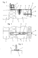
- Fig. 1
- eine Schrägsicht eines Wandabschnittes mit einer Vorrichtung zum Abstützen von Fenster- oder Türrahmen;
- Fig. 2
- einen Vertikalschnitt durch eine Wand mit einem einzusetzenden Fenster- oder Türrahmen, wobei zwei Varianten ineinandergezeichnet dargestellt sind;
- Fig. 3
- eine Draufsicht auf die Darstellung in
Fig. 2 ; - Fig. 4
- eine Detaildarstellung für eine Möglichkeit des Eingriffes eines Verstellelementes;
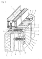
- Fig. 5
- eine Schrägsicht eines Wandabschnittes mit einer gegenüber
Fig. 1 geänderten Ausführungsvariante einer Vorrichtung zum Abstützen eines Fenster- oder Türrahmens.
- Fig. 1
- an oblique view of a wall portion with a device for supporting window or door frame;
- Fig. 2
- a vertical section through a wall with a window or door frame to be inserted, wherein two variants are shown drawn together;
- Fig. 3
- a top view of the illustration in
Fig. 2 ; - Fig. 4
- a detailed representation of a possibility of the intervention of an adjusting element;
- Fig. 5
- an oblique view of a wall portion with an opposite
Fig. 1 modified embodiment of a device for supporting a window or door frame.
Bei einer in den
Vorgesehen wird nun eine biegesteife Profilschiene 7, welche einerseits Löcher zum Durchtritt von Befestigungselementen 8 zum Einsatz in Wandabschnitte aus tragfähigem Material und andererseits Öffnungen zum Eingriff oder zum Abstützen eines Verstellelementes 9 für die einstellbare Abstützung eines Fensterrahmens 5 aufweist. Für den Eingriff oder zum Abstützen eines Verstellelementes 9 können auch Öffnungen vorgesehen werden, in welche ein freies Ende des Verstellelementes 9 formschlüssig eingreifen kann. Auch eine direkte form- und kraftschlüssige Verbindung zwischen einem solchen Verstellelement 9 und der Profilschiene 7 ist möglich. In einem solchen Falle müsste die Profilschiene 7 jedoch bereits mit dem Verstellelement 9 versehen an die Baustelle angeliefert werden. Eine Variante für eine formschlüssige Verbindung kann der
Bei der gezeigten Ausführungsvariante ist die Profilschiene als im Querschnitt C-förmiges Profilelement ausgebildet. Es ist durchaus denkbar, die Profilschiene als Hohlprofilelement oder beispielsweise als im Querschnitt etwa U- oder I-förmiges Profilelement auszubilden. Für eine zusätzliche Verstellmöglichkeit der Profilschiene 7 sind in dieser Langlöcher 11 vorhanden, durch welche das Befestigungselement 8 eingesetzt wird.In the embodiment shown, the profile rail is designed as a cross-sectionally C-shaped profile element. It is quite conceivable to design the profile rail as a hollow profile element or, for example, as a profile element which is approximately U-shaped or I-shaped in cross-section. For an additional adjustment of the
Wie schon erwähnt, ist die Profilschiene 7 beim gezeigten Ausführungsbeispiel als im Wesentlichen im Querschnitt C-förmiges Profilelement ausgebildet. Dabei sind an den freien Randbereichen der Profilschiene 7 gegeneinander gerichtet nach innen abragende Stege 12 vorgesehen, welche an beiden Längsrändern der Profilschiene Führungsnuten 13 bilden.As already mentioned, the
Aufgrund dieser Ausgestaltung kann eine Halteschiene 14 formschlüssig in die Profilschiene 7 eingeschoben werden. Ein solches Einschieben einer Halteschiene 14 ist natürlich auch dann möglich, wenn die Profilschiene 7 als Hohlprofil ausgebildet ist.Due to this configuration, a retaining
Die Halteschiene 14 kann als Hohl- oder Vollprofil oder aber als Flachprofil ausgebildet sein. Ob die Halteschiene 14 ebenfalls biegesteif sein soll oder muss oder eben nicht, wird je nach Einsatzzweck gewählt.The retaining
Weiter kann die Halteschiene 14 als geradliniges Element ausgebildet werden und in einem solchen Falle beispielsweise als Verlängerung der Profilschiene 7 dienen. Bei der gezeigten Ausführungsform weist die Halteschiene 14 zwei in einem annähernd rechten Winkel zueinander stehende Abschnitte 15 und 16 auf. Der eine Abschnitt 15 ist in die Profilschiene 7 einschiebbar und der andere Abschnitt 16 dient zur Befestigung an einem an die Wandöffnung angrenzenden Wandabschnitt 17. Gerade bei Ziegeln 18 mit Hohlkammern 19 ist eine Befestigung quer zu den Hohlkammern 19 wesentlich wirkungsvoller. Die Art der Befestigung mit einem Befestigungselement 20 kann den
Die Halteschiene selbst kann mit einem oder mehreren Löchern 21 versehen werden, wobei solche Löcher teilweise auch als Langlöcher ausgeführt sein können. Die Löcher 21 dienen zum Einsatz des Befestigungselementes 20 oder aber zur gegenseitigen Verbindung zwischen einer Halteschiene 14 und einer Profilschiene 7.The support rail itself can be provided with one or
Bei einer Konstruktion mit einer Profilschiene 7 und zusätzlich einer Halteschiene 14 ist es denkbar, dass die Profilschiene 7 gar nicht auf der Begrenzung 6 der Wandöffnung, d.h. auf der Oberseite des Mauerwerkes 2 abgestützt ist, sondern freitragend mit geringem Abstand angeordnet ist und über die Halteschiene 14 und den entsprechenden Abschnitt 16 an der Innenbegrenzung 17 der Wand befestigt wird.In a construction with a profiled
Für die Abstützung eines Fensterrahmens 5 im Bereich eines Wandabschnittes aus nicht tragfähigem Material mittels einer Profilschiene 7 bestehen also mehrere Möglichkeiten der Befestigung der Profilschiene 7 an einem Wandabschnitt aus tragfähigem Material. Die
Die Ausgestaltung nach
Die dargestellte Ausführungsvariante sieht vor, dass die Halteschiene 14 an ihrem einen mit der Profilschiene 7 in Wirkverbindung stehenden Abschnitt 15 ein Langloch 22 aufweist. Die Profilschiene 7 weist eine Gewindebohrung 7 auf, wobei auch mehrere mit Abstand aufeinander folgende Gewindebohrungen vorgesehen werden können. Durch das Langloch 22 hindurch wird eine Schraube 23 in eine Gewindebohrung an der Profilschiene 7 eingesetzt. Die Schraube 23 wird nicht von vorneherein fest angezogen, so dass die Halteschiene 14 und die Profilschiene 7 relativ zueinander verschiebbar bleiben, bis die endgültige Lage fixiert ist. Anschließend kann die Schraube 23 in einfacher Weise festgezogen werden, so dass Halteschiene 14 und Profilschiene 7 gegenseitig festgelegt sind.The illustrated embodiment provides that the retaining
Es ist auch denkbar, anstelle der Schraube 23 eine Art Niet vorzusehen, der ein gegenseitiges Verschieben zwischen Profilschiene 7 und Halteschiene 14 in einem Ausmaß zulässt, das durch die Länge des Langloches 22 begrenzt ist. Zum gegenseitigen Festlegen der Profilschiene 7 und der Halteschiene 14 kann dannzumal eine zusätzliche Schraube durch das Langloch 22 hindurch in eine zur Verfügung stehende Gewindebohrung in der Profilschiene 7 eingedreht werden.It is also conceivable, instead of the
Nicht nur die Profilschiene 7, sondern auch die Halteschiene 14 kann als Metallelement oder aus Kunststoff gefertigt werden. Gerade dann, wenn Wärme- oder Kältebrücken gänzlich ausgeschaltet werden sollen, erweist sich die Verwendung von Kunststoffelementen, beispielsweise von glasfaserverstärkten Kunststoffelementen, als vorteilhaft.Not only the
Claims (9)
- Use of a profiled rail for supporting window or door frames on the boundary of a wall aperture in a wall, formed by the upper side of the brickwork, which optionally is partly formed from resilient, non load-bearing material, for example from insulation layers, characterised in that a rigid straight profiled rail (7) is provided, which over its entire length is formed continuously as a hollow profiled element or as a profiled element of approximately U, C or I-shaped cross-section, and which has holes (11) for the passage of fastening elements (8) for insertion at the boundary (6) in wall sections consisting of load-bearing material, wherein the profiled rail (7) is fastened via a slot (11) to the boundary (6) of a wall section and is rotated and optionally displaced in relation to the axis of the fastening element (8) so as to adjust the window or door frame, and is further provided with an adjusting element (9) and with more than one opening for engaging or for supporting the adjusting element (9), wherein the adjusting element (9) for adjustable support of a window or door frame (5) in its plane is brought into engagement at one free end with one or other of these openings and wherein after adjusting the position of the window or door frame with the already inserted fastening element (8) or else by additional fastening elements (8) the profiled rail (7) is secured with regard to rotation and displacement.
- Use according to Claim 1, characterised in that the profiled rail (7), which in cross-section is in the form of a C-shaped profiled element, is provided on the free edge zones with inwardly projecting webs (12) directed towards one another to form guide grooves (13) on either side.
- Use according to Claims 1 and 2, characterised by a retaining rail (14) which can be inserted in a form-locking manner into the profiled rail (7) or into guide grooves (13) thereof.
- Use according to Claim 3, characterised in that the retaining rail (14) is in the form of a hollow or solid profile.
- Use according to Claim 3 or 4, characterised in that the retaining rail (14) is in the form of a flat profile.
- Use according to any one of Claims 3 to 5, characterised in that the retaining rail (14) has two portions (15,16) disposed approximately at right angles to one another, wherein one portion (15) can be inserted into the profiled rail (7) and the other portion (16) is designed to be fastened to a wall portion (17) adjacent the wall aperture.
- Use according to any one of Claims 3 to 6, characterised in that, for the insertion of fastening elements (20), the retaining rail (14) is provided with one or more holes (21), for example also in the form of slots.
- Use according to any one of Claims 3 to 7, characterised in that the retaining rail (14) is held captive on the profiled rail (7) and is guided displaceably on the latter in its longitudinal direction and can be secured thereon.
- Use according to Claim 8, characterised in that, on its portion (15) in operative connection with the profiled rail (7), the retaining rail (14) has a slot (22) through which a screw (23) engages in a threaded bore in the profiled rail (7).
Applications Claiming Priority (4)
| Application Number | Priority Date | Filing Date | Title |
|---|---|---|---|
| DE29805225U | 1998-03-23 | ||
| DE29805225 | 1998-03-23 | ||
| DE29816780U | 1998-09-18 | ||
| DE29816780U DE29816780U1 (en) | 1998-03-23 | 1998-09-18 | Device for supporting window or door frames on the boundary of a wall opening |
Publications (4)
| Publication Number | Publication Date |
|---|---|
| EP0945577A2 EP0945577A2 (en) | 1999-09-29 |
| EP0945577A3 EP0945577A3 (en) | 2000-04-05 |
| EP0945577B1 EP0945577B1 (en) | 2008-05-28 |
| EP0945577B2 true EP0945577B2 (en) | 2010-03-24 |
Family
ID=26061350
Family Applications (1)
| Application Number | Title | Priority Date | Filing Date |
|---|---|---|---|
| EP99104333A Expired - Lifetime EP0945577B2 (en) | 1998-03-23 | 1999-03-04 | Use of profile bar to support door or window frames |
Country Status (2)
| Country | Link |
|---|---|
| EP (1) | EP0945577B2 (en) |
| AT (1) | ATE397143T1 (en) |
Cited By (8)
| Publication number | Priority date | Publication date | Assignee | Title |
|---|---|---|---|---|
| DE102011002245A1 (en) | 2011-04-21 | 2012-10-25 | Sfs Intec Holding Ag | Fastening device to a masonry |
| DE202012008857U1 (en) | 2012-09-17 | 2012-11-15 | Ejot Baubefestigungen Gmbh | Wall installation system |
| DE102016213293A1 (en) | 2016-07-20 | 2018-01-25 | Adolf Würth GmbH & Co. KG | Fitting, fitting and method for fixing window and door frames |
| DE102016124008A1 (en) | 2016-12-12 | 2018-06-14 | Adolf Würth Gmbh & Co Kg | Fitting for securing window and door frames to a soffit |
| EP3351715A1 (en) | 2017-01-20 | 2018-07-25 | Fisco GmbH | Door or window frame for mounting a door or window frame to a wall |
| EP3351716A1 (en) | 2017-01-20 | 2018-07-25 | Fisco GmbH | Door or window frame with a mounting frame |
| DE102018100283A1 (en) | 2017-01-20 | 2018-07-26 | FISCO GmbH | Door or window frame with a mounting frame |
| DE102018100281A1 (en) | 2017-01-20 | 2018-07-26 | FISCO GmbH | Door or window frame for mounting a door or window frame to a wall |
Families Citing this family (27)
| Publication number | Priority date | Publication date | Assignee | Title |
|---|---|---|---|---|
| FR2857401B1 (en) * | 2003-07-08 | 2005-08-26 | Ixia Fixation | SPACER FOR ANCHORING LEG |
| DE20311512U1 (en) * | 2003-07-25 | 2004-11-25 | Sfs Intec Holding Ag | Console for supporting and fixing window or door frames at the boundary of a wall opening |
| DE20311513U1 (en) * | 2003-07-25 | 2004-11-25 | Sfs Intec Holding Ag | Device for supporting and securing window or door frames to the boundary of a wall opening |
| PL1544400T3 (en) * | 2003-12-15 | 2009-04-30 | Schreinerei Zimmerei Lothar Kleinbylen | Fixing device |
| WO2006075155A1 (en) * | 2005-01-13 | 2006-07-20 | Allmu A.S. | Method, device, connector and combination |
| EP1845227A1 (en) | 2006-04-12 | 2007-10-17 | Dietrich Anton Fuchs | Device for fixing a frame of a window |
| EP2226456B1 (en) * | 2009-03-02 | 2014-06-25 | VKR Holding A/S | Set of fittings adapted for mounting a fixed frame of a window or door structure and method of mounting |
| DE202009009816U1 (en) * | 2009-07-17 | 2010-12-02 | Chempe Gmbh & Co. Kg | Angle for fixing a component |
| DE202009010497U1 (en) * | 2009-08-03 | 2010-12-16 | Chempe Gmbh & Co. Kg | Angle for fixing a component |
| DE202011108043U1 (en) * | 2011-11-18 | 2012-01-12 | Knelsen Gmbh | Device for fixing a building in a building opening |
| RU2472909C1 (en) * | 2012-01-20 | 2013-01-20 | Сергей Геннадьевич Андреянов | Device to install and fix frames in wall openings |
| WO2013109164A1 (en) * | 2012-01-20 | 2013-07-25 | Andreyanov Sergey Gennadevich | Device for mounting and fastening frames in wall openings |
| DE102013101422B3 (en) | 2013-02-13 | 2014-08-07 | Oliver Offenburger | Mounting system for supporting, fixing and positioning of components |
| PL235307B1 (en) * | 2015-09-17 | 2020-06-29 | Ergo Plus Polska Spolka Z Ograniczona Odpowiedzialnoscia | System profile for mounting and thermally insulating of windows, facades and doors |
| PL414259A1 (en) | 2015-10-04 | 2017-04-10 | Marbet Spółka Z Ograniczoną Odpowiedzialnością | Method for mounting the door and window joinery and the set of the door and window joinery assembly elements |
| DE202016101375U1 (en) | 2016-03-11 | 2016-03-29 | Sfs Intec Holding Ag | Device for supporting and securing window or door frames to the boundary of a wall opening |
| DE102018101827A1 (en) * | 2018-01-26 | 2019-08-01 | Adolf Würth Gmbh & Co Kg | Burglary resistance Installation of a frame on a reveal with functional material |
| DE102018101831A1 (en) | 2018-01-26 | 2019-08-01 | Adolf Würth Gmbh & Co Kg | Frame assembly in the area of a soffit of an anchoring ground by means of retaining element and fasteners |
| BE1026064B1 (en) * | 2018-03-02 | 2019-10-03 | Alu Log Nv | A method and kit for placing façade elements |
| DE202018101399U1 (en) | 2018-03-13 | 2018-04-04 | Sfs Intec Holding Ag | Support bracket for door and window attachment |
| DE102018117362A1 (en) * | 2018-07-18 | 2020-01-23 | Simone Niemann | Fastening device for a window or door frame on a masonry |
| PL3628806T3 (en) | 2018-09-28 | 2023-10-30 | SFS Group International AG | Device for fixing a component in a wall opening |
| EP3696361B8 (en) | 2019-02-15 | 2022-05-04 | SFS Group International AG | Device for supporting window or door elements |
| DE202019103431U1 (en) | 2019-06-19 | 2020-06-23 | HUECK System GmbH & Co. KG | Two-part frame attachment |
| EP3865654A1 (en) | 2020-02-14 | 2021-08-18 | SFS Intec Holding AG | Device for supporting window or door elements |
| DE102021107547A1 (en) | 2021-03-25 | 2022-09-29 | Adolf Würth Gmbh & Co Kg | Installation of a frame on an opening in an anchoring base using a flexurally stable connection between the bracket profile and the attachment |
| AT524668B1 (en) * | 2021-09-08 | 2022-08-15 | Ifn Holding Ag | mounting element |
Citations (1)
| Publication number | Priority date | Publication date | Assignee | Title |
|---|---|---|---|---|
| EP0491010B1 (en) † | 1990-03-19 | 1997-02-26 | Igela A/S | A method for joining two structural members by the aid of an adjustable fastener, and a mounting for use with said method |
Family Cites Families (3)
| Publication number | Priority date | Publication date | Assignee | Title |
|---|---|---|---|---|
| AT404380B (en) * | 1994-10-04 | 1998-11-25 | Fuchs Dietrich Anton | DEVICE, IN PARTICULAR DISTANCE ANCHOR FOR ADJUSTMENT AND FASTENING OF FRAME |
| DE29510005U1 (en) * | 1995-06-20 | 1995-08-31 | Schedel Gmbh Eduard | Fastening element for doors or windows |
| DE29619703U1 (en) * | 1996-11-13 | 1997-01-09 | Mft Moderne Fenster Technik Gm | Mounting kit for fastening a window or door frame formed from hollow profiles in an opening in a building |
-
1999
- 1999-03-04 EP EP99104333A patent/EP0945577B2/en not_active Expired - Lifetime
- 1999-03-04 AT AT99104333T patent/ATE397143T1/en active
Patent Citations (1)
| Publication number | Priority date | Publication date | Assignee | Title |
|---|---|---|---|---|
| EP0491010B1 (en) † | 1990-03-19 | 1997-02-26 | Igela A/S | A method for joining two structural members by the aid of an adjustable fastener, and a mounting for use with said method |
Cited By (8)
| Publication number | Priority date | Publication date | Assignee | Title |
|---|---|---|---|---|
| DE102011002245A1 (en) | 2011-04-21 | 2012-10-25 | Sfs Intec Holding Ag | Fastening device to a masonry |
| DE202012008857U1 (en) | 2012-09-17 | 2012-11-15 | Ejot Baubefestigungen Gmbh | Wall installation system |
| DE102016213293A1 (en) | 2016-07-20 | 2018-01-25 | Adolf Würth GmbH & Co. KG | Fitting, fitting and method for fixing window and door frames |
| DE102016124008A1 (en) | 2016-12-12 | 2018-06-14 | Adolf Würth Gmbh & Co Kg | Fitting for securing window and door frames to a soffit |
| EP3351715A1 (en) | 2017-01-20 | 2018-07-25 | Fisco GmbH | Door or window frame for mounting a door or window frame to a wall |
| EP3351716A1 (en) | 2017-01-20 | 2018-07-25 | Fisco GmbH | Door or window frame with a mounting frame |
| DE102018100283A1 (en) | 2017-01-20 | 2018-07-26 | FISCO GmbH | Door or window frame with a mounting frame |
| DE102018100281A1 (en) | 2017-01-20 | 2018-07-26 | FISCO GmbH | Door or window frame for mounting a door or window frame to a wall |
Also Published As
| Publication number | Publication date |
|---|---|
| EP0945577B1 (en) | 2008-05-28 |
| ATE397143T1 (en) | 2008-06-15 |
| EP0945577A2 (en) | 1999-09-29 |
| EP0945577A3 (en) | 2000-04-05 |
Similar Documents
| Publication | Publication Date | Title |
|---|---|---|
| EP0945577B2 (en) | Use of profile bar to support door or window frames | |
| EP2514899B1 (en) | Fixing device for fixing to a wall | |
| EP0476289A1 (en) | Façade construction comprising a support structure with a profile structure fixed on the front | |
| AT4958U1 (en) | DEVICE FOR SUPPORTING WINDOW OR DOOR FRAMES ON THE LIMITATION OF A WALL OPENING | |
| EP2060699B1 (en) | Fixing device for covering elements or a supporting structure for covering elements | |
| EP1840315B1 (en) | Frame construction | |
| EP1500767B1 (en) | Support and fixing device for door or window frames at the edge of wall openings | |
| EP2159345B1 (en) | Mount for covering elements | |
| EP1500768B1 (en) | Support and fixing device for door or window frames at the edge of wall openings | |
| EP3241974B1 (en) | Assembly for a seal, in particular for a contact seal or for an automatically lowerable floor seal for doors | |
| EP0065296A1 (en) | Fixed or gliding distancing support for wall claddings | |
| EP2213825B1 (en) | Frame beam of a frame for doors or gates with an attachment device | |
| EP1840314B1 (en) | Fire resistant construction element | |
| DE19831453C2 (en) | Adjustable attachment for objects, especially glass plates on a substructure | |
| WO2008110248A1 (en) | Device with a mounting insert for fastening fitting parts to hollow profiles and method for attaching said mounting insert to the hollow profile | |
| EP1659246A1 (en) | Hinge for shutters | |
| DE3527224A1 (en) | Fastening device for a facade cladding | |
| EP0539672B1 (en) | Fitting for fixing in a two sided undercut groove of a member | |
| EP0826850B1 (en) | Façade load-supporting means | |
| DE19939205A1 (en) | Fastening anchors for anchoring frames and frames provided with them | |
| DE19744832C2 (en) | Arrangement for the installation of a window frame | |
| EP0444552B1 (en) | Fixing bracket for a curtain wall mounting-device system | |
| EP1653030B1 (en) | Hinge with at least two hinge elements for assembly with a supporting and receiving element | |
| EP3889384A1 (en) | Extruded window or door hollow section profile, system with such a hollow section profile and frame made from same | |
| DE19730145C2 (en) | Hinge part for arrangement on wooden or metal frames for windows or doors |
Legal Events
| Date | Code | Title | Description |
|---|---|---|---|
| PUAI | Public reference made under article 153(3) epc to a published international application that has entered the european phase |
Free format text: ORIGINAL CODE: 0009012 |
|
| AK | Designated contracting states |
Kind code of ref document: A2 Designated state(s): AT BE CH CY DE DK ES FI FR GB GR IE IT LI LU NL PT SE |
|
| AX | Request for extension of the european patent |
Free format text: AL;LT;LV;MK;RO;SI |
|
| PUAL | Search report despatched |
Free format text: ORIGINAL CODE: 0009013 |
|
| AK | Designated contracting states |
Kind code of ref document: A3 Designated state(s): AT BE CH CY DE DK ES FI FR GB GR IE IT LI LU MC NL PT SE |
|
| AX | Request for extension of the european patent |
Free format text: AL;LT;LV;MK;RO;SI |
|
| 17P | Request for examination filed |
Effective date: 20000508 |
|
| AKX | Designation fees paid |
Free format text: AT BE CH CY DE DK ES FI FR GB GR IE IT LI LU NL PT SE |
|
| AXX | Extension fees paid |
Free format text: SI PAYMENT 20000508 |
|
| RAP1 | Party data changed (applicant data changed or rights of an application transferred) |
Owner name: SFS INTEC HOLDING AG |
|
| 17Q | First examination report despatched |
Effective date: 20030206 |
|
| APBN | Date of receipt of notice of appeal recorded |
Free format text: ORIGINAL CODE: EPIDOSNNOA2E |
|
| APBR | Date of receipt of statement of grounds of appeal recorded |
Free format text: ORIGINAL CODE: EPIDOSNNOA3E |
|
| APBK | Appeal reference recorded |
Free format text: ORIGINAL CODE: EPIDOSNREFNE |
|
| APAF | Appeal reference modified |
Free format text: ORIGINAL CODE: EPIDOSCREFNE |
|
| APBT | Appeal procedure closed |
Free format text: ORIGINAL CODE: EPIDOSNNOA9E |
|
| GRAP | Despatch of communication of intention to grant a patent |
Free format text: ORIGINAL CODE: EPIDOSNIGR1 |
|
| RTI1 | Title (correction) |
Free format text: USE OF PROFILE BAR TO SUPPORT DOOR OR WINDOWS FRAMES |
|
| GRAS | Grant fee paid |
Free format text: ORIGINAL CODE: EPIDOSNIGR3 |
|
| GRAA | (expected) grant |
Free format text: ORIGINAL CODE: 0009210 |
|
| AK | Designated contracting states |
Kind code of ref document: B1 Designated state(s): AT BE CH CY DE DK ES FI FR GB GR IE IT LI LU NL PT SE |
|
| AX | Request for extension of the european patent |
Extension state: SI |
|
| REG | Reference to a national code |
Ref country code: GB Ref legal event code: FG4D Free format text: NOT ENGLISH |
|
| REG | Reference to a national code |
Ref country code: CH Ref legal event code: NV Representative=s name: JUERG PLUESS SFS INTEC AG INTELLECTUAL PROPERTY MA Ref country code: CH Ref legal event code: EP |
|
| REF | Corresponds to: |
Ref document number: 59914766 Country of ref document: DE Date of ref document: 20080710 Kind code of ref document: P |
|
| REG | Reference to a national code |
Ref country code: IE Ref legal event code: FG4D Free format text: LANGUAGE OF EP DOCUMENT: GERMAN |
|
| PLBI | Opposition filed |
Free format text: ORIGINAL CODE: 0009260 |
|
| 26 | Opposition filed |
Opponent name: FABRICIUS FASTENER GMBH Effective date: 20080809 |
|
| PG25 | Lapsed in a contracting state [announced via postgrant information from national office to epo] |
Ref country code: FI Free format text: LAPSE BECAUSE OF FAILURE TO SUBMIT A TRANSLATION OF THE DESCRIPTION OR TO PAY THE FEE WITHIN THE PRESCRIBED TIME-LIMIT Effective date: 20080528 Ref country code: ES Free format text: LAPSE BECAUSE OF FAILURE TO SUBMIT A TRANSLATION OF THE DESCRIPTION OR TO PAY THE FEE WITHIN THE PRESCRIBED TIME-LIMIT Effective date: 20080908 |
|
| NLR1 | Nl: opposition has been filed with the epo |
Opponent name: FABRICIUS FASTENER GMBH |
|
| PG25 | Lapsed in a contracting state [announced via postgrant information from national office to epo] |
Ref country code: NL Free format text: LAPSE BECAUSE OF FAILURE TO SUBMIT A TRANSLATION OF THE DESCRIPTION OR TO PAY THE FEE WITHIN THE PRESCRIBED TIME-LIMIT Effective date: 20080528 |
|
| NLV1 | Nl: lapsed or annulled due to failure to fulfill the requirements of art. 29p and 29m of the patents act | ||
| REG | Reference to a national code |
Ref country code: IE Ref legal event code: FD4D |
|
| PG25 | Lapsed in a contracting state [announced via postgrant information from national office to epo] |
Ref country code: SE Free format text: LAPSE BECAUSE OF FAILURE TO SUBMIT A TRANSLATION OF THE DESCRIPTION OR TO PAY THE FEE WITHIN THE PRESCRIBED TIME-LIMIT Effective date: 20080828 Ref country code: PT Free format text: LAPSE BECAUSE OF FAILURE TO SUBMIT A TRANSLATION OF THE DESCRIPTION OR TO PAY THE FEE WITHIN THE PRESCRIBED TIME-LIMIT Effective date: 20081028 Ref country code: IE Free format text: LAPSE BECAUSE OF FAILURE TO SUBMIT A TRANSLATION OF THE DESCRIPTION OR TO PAY THE FEE WITHIN THE PRESCRIBED TIME-LIMIT Effective date: 20080528 Ref country code: DK Free format text: LAPSE BECAUSE OF FAILURE TO SUBMIT A TRANSLATION OF THE DESCRIPTION OR TO PAY THE FEE WITHIN THE PRESCRIBED TIME-LIMIT Effective date: 20080528 |
|
| PLAX | Notice of opposition and request to file observation + time limit sent |
Free format text: ORIGINAL CODE: EPIDOSNOBS2 |
|
| PLBB | Reply of patent proprietor to notice(s) of opposition received |
Free format text: ORIGINAL CODE: EPIDOSNOBS3 |
|
| PLAB | Opposition data, opponent's data or that of the opponent's representative modified |
Free format text: ORIGINAL CODE: 0009299OPPO |
|
| R26 | Opposition filed (corrected) |
Opponent name: FABRICIUS FASTENER GMBH Effective date: 20080809 |
|
| PLAB | Opposition data, opponent's data or that of the opponent's representative modified |
Free format text: ORIGINAL CODE: 0009299OPPO |
|
| PG25 | Lapsed in a contracting state [announced via postgrant information from national office to epo] |
Ref country code: IT Free format text: LAPSE BECAUSE OF FAILURE TO SUBMIT A TRANSLATION OF THE DESCRIPTION OR TO PAY THE FEE WITHIN THE PRESCRIBED TIME-LIMIT Effective date: 20080528 |
|
| R26 | Opposition filed (corrected) |
Opponent name: FABRICIUS FASTENER GMBH Effective date: 20080809 |
|
| BERE | Be: lapsed |
Owner name: SFS INTEC HOLDING A.G. Effective date: 20090331 |
|
| GBPC | Gb: european patent ceased through non-payment of renewal fee |
Effective date: 20090304 |
|
| PLBP | Opposition withdrawn |
Free format text: ORIGINAL CODE: 0009264 |
|
| RTI2 | Title (correction) |
Free format text: USE OF PROFILE BAR TO SUPPORT DOOR OR WINDOW FRAMES |
|
| PUAH | Patent maintained in amended form |
Free format text: ORIGINAL CODE: 0009272 |
|
| STAA | Information on the status of an ep patent application or granted ep patent |
Free format text: STATUS: PATENT MAINTAINED AS AMENDED |
|
| PG25 | Lapsed in a contracting state [announced via postgrant information from national office to epo] |
Ref country code: BE Free format text: LAPSE BECAUSE OF NON-PAYMENT OF DUE FEES Effective date: 20090331 |
|
| 27A | Patent maintained in amended form |
Effective date: 20100324 |
|
| AK | Designated contracting states |
Kind code of ref document: B2 Designated state(s): AT BE CH CY DE DK ES FI FR GB GR IE IT LI LU NL PT SE |
|
| AX | Request for extension of the european patent |
Extension state: SI |
|
| REG | Reference to a national code |
Ref country code: CH Ref legal event code: AEN Free format text: AUFRECHTERHALTUNG DES PATENTES IN GEAENDERTER FORM |
|
| PG25 | Lapsed in a contracting state [announced via postgrant information from national office to epo] |
Ref country code: GB Free format text: LAPSE BECAUSE OF NON-PAYMENT OF DUE FEES Effective date: 20090304 |
|
| PG25 | Lapsed in a contracting state [announced via postgrant information from national office to epo] |
Ref country code: GR Free format text: LAPSE BECAUSE OF FAILURE TO SUBMIT A TRANSLATION OF THE DESCRIPTION OR TO PAY THE FEE WITHIN THE PRESCRIBED TIME-LIMIT Effective date: 20080829 |
|
| PG25 | Lapsed in a contracting state [announced via postgrant information from national office to epo] |
Ref country code: LU Free format text: LAPSE BECAUSE OF NON-PAYMENT OF DUE FEES Effective date: 20090304 |
|
| PG25 | Lapsed in a contracting state [announced via postgrant information from national office to epo] |
Ref country code: CY Free format text: LAPSE BECAUSE OF FAILURE TO SUBMIT A TRANSLATION OF THE DESCRIPTION OR TO PAY THE FEE WITHIN THE PRESCRIBED TIME-LIMIT Effective date: 20080528 |
|
| REG | Reference to a national code |
Ref country code: DE Ref legal event code: R082 Ref document number: 59914766 Country of ref document: DE Representative=s name: SCHUMACHER & WILLSAU PATENTANWALTSGESELLSCHAFT, DE |
|
| PGFP | Annual fee paid to national office [announced via postgrant information from national office to epo] |
Ref country code: AT Payment date: 20140328 Year of fee payment: 16 |
|
| REG | Reference to a national code |
Ref country code: AT Ref legal event code: MM01 Ref document number: 397143 Country of ref document: AT Kind code of ref document: T Effective date: 20150304 |
|
| PG25 | Lapsed in a contracting state [announced via postgrant information from national office to epo] |
Ref country code: AT Free format text: LAPSE BECAUSE OF NON-PAYMENT OF DUE FEES Effective date: 20150304 |
|
| REG | Reference to a national code |
Ref country code: FR Ref legal event code: PLFP Year of fee payment: 18 |
|
| REG | Reference to a national code |
Ref country code: CH Ref legal event code: NV Representative=s name: JOERG BAUR SFS INTEC AG INTELLECTUAL PROPERTY , CH |
|
| PGFP | Annual fee paid to national office [announced via postgrant information from national office to epo] |
Ref country code: CH Payment date: 20160201 Year of fee payment: 18 |
|
| REG | Reference to a national code |
Ref country code: CH Ref legal event code: NV Representative=s name: JOERG BAUR SFS INTEC AG INTELLECTUAL PROPERTY , CH |
|
| PGFP | Annual fee paid to national office [announced via postgrant information from national office to epo] |
Ref country code: FR Payment date: 20160329 Year of fee payment: 18 |
|
| REG | Reference to a national code |
Ref country code: CH Ref legal event code: PL |
|
| REG | Reference to a national code |
Ref country code: FR Ref legal event code: ST Effective date: 20171130 |
|
| PG25 | Lapsed in a contracting state [announced via postgrant information from national office to epo] |
Ref country code: FR Free format text: LAPSE BECAUSE OF NON-PAYMENT OF DUE FEES Effective date: 20170331 |
|
| PG25 | Lapsed in a contracting state [announced via postgrant information from national office to epo] |
Ref country code: LI Free format text: LAPSE BECAUSE OF NON-PAYMENT OF DUE FEES Effective date: 20170331 Ref country code: CH Free format text: LAPSE BECAUSE OF NON-PAYMENT OF DUE FEES Effective date: 20170331 |
|
| PGFP | Annual fee paid to national office [announced via postgrant information from national office to epo] |
Ref country code: DE Payment date: 20180322 Year of fee payment: 20 |
|
| REG | Reference to a national code |
Ref country code: DE Ref legal event code: R071 Ref document number: 59914766 Country of ref document: DE |