EP1544376A2 - Section de coffrage intérieur pour l'érection d'une section de construction - Google Patents
Section de coffrage intérieur pour l'érection d'une section de construction Download PDFInfo
- Publication number
- EP1544376A2 EP1544376A2 EP04025905A EP04025905A EP1544376A2 EP 1544376 A2 EP1544376 A2 EP 1544376A2 EP 04025905 A EP04025905 A EP 04025905A EP 04025905 A EP04025905 A EP 04025905A EP 1544376 A2 EP1544376 A2 EP 1544376A2
- Authority
- EP
- European Patent Office
- Prior art keywords
- inner formwork
- section
- ribs
- strip
- formwork
- Prior art date
- Legal status (The legal status is an assumption and is not a legal conclusion. Google has not performed a legal analysis and makes no representation as to the accuracy of the status listed.)
- Withdrawn
Links
Images


Classifications
-
- E—FIXED CONSTRUCTIONS
- E04—BUILDING
- E04G—SCAFFOLDING; FORMS; SHUTTERING; BUILDING IMPLEMENTS OR AIDS, OR THEIR USE; HANDLING BUILDING MATERIALS ON THE SITE; REPAIRING, BREAKING-UP OR OTHER WORK ON EXISTING BUILDINGS
- E04G11/00—Forms, shutterings, or falsework for making walls, floors, ceilings, or roofs
- E04G11/06—Forms, shutterings, or falsework for making walls, floors, ceilings, or roofs for walls, e.g. curved end panels for wall shutterings; filler elements for wall shutterings; shutterings for vertical ducts
- E04G11/20—Movable forms; Movable forms for moulding cylindrical, conical or hyperbolical structures; Templates serving as forms for positioning blocks or the like
- E04G11/28—Climbing forms, i.e. forms which are not in contact with the poured concrete during lifting from layer to layer and which are anchored in the hardened concrete
-
- E—FIXED CONSTRUCTIONS
- E04—BUILDING
- E04G—SCAFFOLDING; FORMS; SHUTTERING; BUILDING IMPLEMENTS OR AIDS, OR THEIR USE; HANDLING BUILDING MATERIALS ON THE SITE; REPAIRING, BREAKING-UP OR OTHER WORK ON EXISTING BUILDINGS
- E04G11/00—Forms, shutterings, or falsework for making walls, floors, ceilings, or roofs
- E04G11/06—Forms, shutterings, or falsework for making walls, floors, ceilings, or roofs for walls, e.g. curved end panels for wall shutterings; filler elements for wall shutterings; shutterings for vertical ducts
- E04G11/062—Forms for curved walls
- E04G11/065—Forms for curved walls with mechanical means to modify the curvature
-
- F—MECHANICAL ENGINEERING; LIGHTING; HEATING; WEAPONS; BLASTING
- F03—MACHINES OR ENGINES FOR LIQUIDS; WIND, SPRING, OR WEIGHT MOTORS; PRODUCING MECHANICAL POWER OR A REACTIVE PROPULSIVE THRUST, NOT OTHERWISE PROVIDED FOR
- F03D—WIND MOTORS
- F03D13/00—Assembly, mounting or commissioning of wind motors; Arrangements specially adapted for transporting wind motor components
- F03D13/10—Assembly of wind motors; Arrangements for erecting wind motors
-
- F—MECHANICAL ENGINEERING; LIGHTING; HEATING; WEAPONS; BLASTING
- F05—INDEXING SCHEMES RELATING TO ENGINES OR PUMPS IN VARIOUS SUBCLASSES OF CLASSES F01-F04
- F05B—INDEXING SCHEME RELATING TO WIND, SPRING, WEIGHT, INERTIA OR LIKE MOTORS, TO MACHINES OR ENGINES FOR LIQUIDS COVERED BY SUBCLASSES F03B, F03D AND F03G
- F05B2230/00—Manufacture
- F05B2230/60—Assembly methods
- F05B2230/61—Assembly methods using auxiliary equipment for lifting or holding
-
- Y—GENERAL TAGGING OF NEW TECHNOLOGICAL DEVELOPMENTS; GENERAL TAGGING OF CROSS-SECTIONAL TECHNOLOGIES SPANNING OVER SEVERAL SECTIONS OF THE IPC; TECHNICAL SUBJECTS COVERED BY FORMER USPC CROSS-REFERENCE ART COLLECTIONS [XRACs] AND DIGESTS
- Y02—TECHNOLOGIES OR APPLICATIONS FOR MITIGATION OR ADAPTATION AGAINST CLIMATE CHANGE
- Y02E—REDUCTION OF GREENHOUSE GAS [GHG] EMISSIONS, RELATED TO ENERGY GENERATION, TRANSMISSION OR DISTRIBUTION
- Y02E10/00—Energy generation through renewable energy sources
- Y02E10/70—Wind energy
- Y02E10/72—Wind turbines with rotation axis in wind direction
-
- Y—GENERAL TAGGING OF NEW TECHNOLOGICAL DEVELOPMENTS; GENERAL TAGGING OF CROSS-SECTIONAL TECHNOLOGIES SPANNING OVER SEVERAL SECTIONS OF THE IPC; TECHNICAL SUBJECTS COVERED BY FORMER USPC CROSS-REFERENCE ART COLLECTIONS [XRACs] AND DIGESTS
- Y02—TECHNOLOGIES OR APPLICATIONS FOR MITIGATION OR ADAPTATION AGAINST CLIMATE CHANGE
- Y02P—CLIMATE CHANGE MITIGATION TECHNOLOGIES IN THE PRODUCTION OR PROCESSING OF GOODS
- Y02P70/00—Climate change mitigation technologies in the production process for final industrial or consumer products
- Y02P70/50—Manufacturing or production processes characterised by the final manufactured product
Definitions
- the invention relates to an inner formwork section for constructing a building section with a circumferentially closed concrete wall whose circumference increases or decreases over the height of the building section, wherein the inner formwork section a circumferentially closed main part whose circumference is at its upper end is greater or smaller than at its lower end, and one Having at the upper end of the main part releasably attached to this climbing ring.
- the invention relates to an inner formwork system for the construction of a Building in several concreting steps, in each of which a building section with the help of an inner formwork section formed from the inner formwork system is built, with at least some of the building sections have an increasing or decreasing over their height circumference and the associated Inner formwork portion a circumferentially closed main part, whose Circumference greater or smaller at its upper end than at its lower end is, and one at the upper end of the main part detachably attached to this climbing ring having
- FIG. 1 Another type of climbing formwork is disclosed, for example, in US Pat. No. 1,478,653 shown and described.
- the essence of such climbing formwork lies in that here the masonry penetrating shuttering anchors are provided to and with which the formwork elements are braced in their entirety, wherein the concreted in a concreting step above each anchor in the sequence be used as foot anchor for the formwork in the next concreting step.
- a new anchor is installed.
- the formwork will then set high when the previous concrete wall section tied because he has the formwork anchors over the entire weight of the formwork has to bear.
- the formwork itself consists of the actual formwork panels and the framework stiffening the formwork panels.
- An inner formwork section of the aforementioned type is known from EP 1 156 175 A2 known.
- An inner formwork section of the aforementioned type is known from EP 1 156 175 A2 known.
- For the construction of a structure with a frustoconical Form is a separate inner formwork section for each of the building sections present whose outer contour of the inner contour of the section of trainees Concrete wall corresponds.
- There are all here for the construction of the building required inner formwork sections completely in front of and above each other would put their outer contour of the inner contour of the entire to be created Concrete wall correspond.
- the disadvantage is the relatively high material consumption for the entire inner formwork.
- an inner formwork which consists of individual Formwork sections ("steel pipe shots") consists.
- the steel pipe shots will be formed by circumferentially adjoining strip elements, which decrease in width over their height.
- the strip elements become assembled on site to the inner formwork sections (formwork pipe sections) and mounted one above the other until the desired height of the structure is reached is.
- the annulus becomes between the outer formwork pipe sections and the inner formwork pipe sections filled with ready-mixed concrete.
- the formwork is lost Formed formwork and can also be static mittragend.
- Such Lost formwork or statically supporting formworks have different Disadvantages, for example, in terms of the cost of materials because the formwork remains in the building and not for another building in turn can be used.
- US 4,577,727 B shows a formwork for the construction of circular structures, at a working platform to different diameters of the structure can be adjusted.
- the inner formwork of this formwork includes a Pressure receiving ring that supports the formwork inside.
- the object of the invention is an inner formwork section or an inner formwork system of the type mentioned, by, or by the material saving is achieved. This is achieved by the invention an inner formwork section having the features of patent claim 1 or by an inner formwork system with the features of claim 13.
- an inner formwork section or inner formwork system can at least parts of one in the construction of a building section used inner formwork section for training in the establishment another building section required inner formwork section be used, whereby the cost of materials is reduced.
- the inner formwork section can do enough of the concrete while concreting absorb applied pressure.
- An inventive inner formwork section or an inventive inner formwork system allows further a rapid and advantageous manufacturing process of the individual building sections of the building.
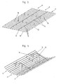
- the wind tower shown schematically in Fig. 1 has a wind turbine 1, the on a frustoconical or conical structure 2 made of reinforced concrete in shape a reinforced concrete tower is stored. This is on top of the reinforced concrete tower a cap 3 made of steel sheet attached, which carries the windmill 1.
- the construction 2 for example, at its upper end a diameter of 1.8m and at its base have a diameter in the range of 5.8m.
- the structure 2 is built in individual concreting steps, in Fig. 1 by the horizontal lines are indicated and in each case a height of, for example 4 to 5m.
- each concreting a building section 4 with built a circumferentially closed concrete wall whose circumference at the top End of the respective building section 4 smaller than at its lower end is.
- all building sections 4 have a frustoconical shape Shape up, with the truncated cone from bottom to top rejuvenated.
- FIG. 2 is an embodiment of an inner formwork section according to the invention shown in simplified form.
- the round in the illustrated embodiment Inner formwork section has a circumferentially closed (shown in FIG Embodiment round) main part 5, at the upper end of a circumferentially closed (Round in the illustrated embodiment) climbing ring 6 solvable is attached.
- the detachable attachment for example, by means of fittings or by means of clamping parts, as explained in more detail below becomes.
- the (in the embodiment shown in cross-section circular) formwork skin of the inner formwork portion becomes integral with all of its outer surface 7 Share formed.
- the main part 5 contributes to the majority of the formwork.
- a contrast, smaller part of the formwork skin is also formed by the climbing ring 6.
- the height h of the formwork skin formed by the climbing ring 6 is preferably less than 1/10 of the height H formed by the main part 5 of the formwork skin.
- the main part 5 is made up of a plurality of strip elements 9, such as This will be explained below in particular with reference to FIGS. 3 to 5.
- the strip elements 9 each have strip-shaped in the insert position vertically extending Formwork skin sections 10, at whose from the concrete wall to be built facing away backs in the operating position vertically extending to inside projecting ribs 11, 12 are mounted. These can be welded on or bolted webs or rails are formed and are preferably perpendicular to the formwork skin sections 10 of these from, preferably extending over the entire height of the main part 5. Two of these ribs 12 extend at the two side edges of the respective Strip element 9 and are preferably flush with the front ends of the formwork skin section 10.
- the peripheral ribs 12 can, for example also by crimping the formwork sheet metal sections 10 existing from sheet metal be formed.
- a rope 15 in the region of the two side edges of the of the several strip elements 9 formed element attached At least to the curvature of the interconnected strip elements a rope 15 in the region of the two side edges of the of the several strip elements 9 formed element attached.
- This rope 15 is still at first so loose that a spacer 16 approximately in the middle of the rope 15 between the strip element 9 and the cable 15 can be inserted.
- the cable 15 is shortened by means of a schematically indicated in Fig. 17 winds 17, wherein the formed element curves, as shown in Fig. 4.
- ropes 15 can also chains or others Traction means are used.
- FIG. 6 A more accurate embodiment of an embodiment such a tension hook is shown in FIG. 6.
- the tension hook 18 is U-shaped, with a side leg 19 on a rib 11th the strip element 9 is screwed.
- the base leg 20 is in the extension direction the rib 11 from the formwork section 10 and the other side legs 21 is penetrated by a clamping screw 22.
- the clamping hooks 18 are used for fastening segments 23 of pressure receiving rings 24 at the strip elements 9.
- the inner formwork section has at least one such pressure receiving ring 24.
- a respective pressure receiving ring 24 is provided with at least some of the strip elements 9, preferably with all Strip elements 9 releasably connected, for which purpose in the illustrated embodiment attached to the ribs 11 clamping hook 18 is present are. It is preferred that at least two different ones for each strip element Ribs 11, 12 attached clamping hooks 18 are present.
- the segments 23 of the pressure receiving rings 24 are pre-curved accordingly and are in the clamping hooks 18 of the example shown in FIG. 4 Curved way, consisting of several strip elements 9 Elements inserted, the clamping screws 22 are initially still open. As a result, the clamping screws 22 are turned off, so that the segments 23 to the ends of the ribs 11, 12 remote from the formwork skin sections 10 be pressed.
- Fig. 5th Such a type lying preassembled element is shown schematically. This element is erected in the sequence and several Such elements become the circumferentially closed main part 5 with each other connected.
- the segments 23 are also connected to each other.
- 23 flange plates 26 welded to the ends of the segments be, which directly or with the interposition of spacers 27 are bolted together.
- a screw connection via an intermediate piece 27 is shown in FIG.
- the intermediate piece has a strip piece 28 on which Flange plates 29 are screwed on both sides, with the flange plates 26 of the segments 23 are screwed.
- the flange plates 29 on the two Ends of the strip piece 28 are V-shaped to each other and the flange plates 26 are aligned to the later disassembly of the To facilitate pressure receiving rings 24 after concreting.
- the circumferentially closed main part 5 is formed in this way.
- the scope of the main part is at his upper end smaller than at its lower end.
- These strip elements thus have an in View seen from bottom to top tapered shape or a trapezoidal shape (preferably an isosceles trapezoid).
- the remaining Strip elements can have a constant width, ie in view seen to be rectangular. It would also be possible and possible for that all strip elements are conically tapered or trapezoidal are.
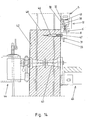
- the climbing ring 6 has in the illustrated embodiment as shown in Fig. 9, a vertical web 8, a part forms the formwork of the inner formwork section and at the top and at the lower end inwardly projecting horizontal webs 30, 31 attached are so that the webs 8, 30 and 31 together form a U-shaped cross-sectional shape exhibit.
- a vertical web 8 At the upper horizontal web 30 is an upwardly projecting spring-like Strip 32 and the lower horizontal web 31 is a downwardly projecting spring-like strip 33 attached, wherein the strips 32, 33 radially further inside than the web 8 lie and welded, for example, to the horizontal webs 30, 31 are.
- the strips 32, 33 extend over most of the circumference of the climbing ring 6.
- the climbing ring 6 consists of several segments 34, which screwed together (or jammed) are. In the illustrated embodiment are at the ends of the segments 34 respectively between the horizontal webs 30, 31 extending flange plates 35 are arranged, which by means of holes in the Flange plates 35 passing through bolts 36 are screwed. In the connection area of two segments 34, the strips 32, 33 interruptions on.
- the ribs 11, 12 of the strip elements 9 have in their upper and lower Slots 37, 38 (see Figures 8 and 14, the slots are shown in Figs. 3 to 5 not shown for simplicity).
- the slots 37 in the upper end regions start from the upper front ends of the ribs 11, 12 and have a V-shaped extended retraction area, as shown in FIG. 8 can be seen.
- the outgoing from the lower front ends of the ribs 11, 12 slots 38 in the lower end portions of the ribs 11, 12 are formed in an analogous manner. To connect the climbing ring this is on the upper end of the Main part 5 is set, with its downwardly projecting bar 33 in the Slots 37 is introduced. At some of the ribs 11, 12, for example at the edge ribs 12 are attached 39 angle.
- angles 39 are connected to the lower horizontal web 31 of the climbing ring 6 by means of terminals 40 braces, as shown in Fig. 10, wherein the lower horizontal web 31 rests on the upper front ends of the ribs 11, 12.
- a Clamping connection would also be a screw for releasable attachment of the Climbing ring 6 on the main part 5 conceivable and possible.
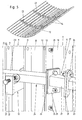
- Such a finished inner formwork section can in the episode in the Erection of a building section are used, as follows will be explained with reference to FIGS. 11 to 14.
- Fig. 11 shows the construction phase, in which a previous building section with the circumferentially closed concrete wall 42 has already been completed.
- an inner and an outer Work platform 44, 45 attached, their training in the present context does not need to be explained in detail.
- On the concrete wall 42 is further the climbing ring 6 'of the construction of the previous building section inserted inner formwork section attached.
- Dowel 46 (see Fig. 14) walled into the concrete wall 42, in which the vertical Web 8 of the climbing ring 6 'passing through bolts 47 are screwed.
- the vertical web 8 of the climbing ring stands on the upper edge 48 of the finished Section of the concrete wall 42 something in front.
- the inner formwork section 50 already at its lifting by means of the hoist 41 and placing on the climbing ring 6 'a reinforcement 52 attached thereto with mounting parts, such as anchors 43 attached.
- the attachment of the reinforcement to the inner formwork section 50 can thus already done on the ground.
- Through holes in the upper end of the main part 5 fixed climbing ring 6 of the inner formwork section 50 are further Bolt performed and screwed in dowel 46, which at later Concreting be concreted to the climbing ring 6 to be produced on the To attach concrete wall.
- an outer formwork section 53 is attached and the between the inner formwork section 50 and the outer formwork section 53 Poured space with concrete to make the building section 4.
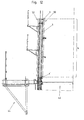
- the construction phase after concreting is shown in Fig. 12.
- the outer formwork section 53 may be formed in a conventional manner.
- the outer formwork section can also consist of strip elements and in be formed the way, as for example from the beginning EP 1 156 175 A2 is known, be formed.
- the outer formwork section is here without climbing rings 6 and without horizontal stiffening Rail formed, since the outer formwork is loaded only on train and Traction forces are much easier to absorb than compressive forces. With others In words, the outer formwork does not require a rigid and shaping support structure, like these in the inner formwork section through the at least one Pressure receiving ring 24 and the climbing rings 6, 6 'is formed.
- the outer formwork section 53 can be removed become. Furthermore, the climbing ring 6 'of the previous building section belonging inner formwork section removed by the bolts 47 are turned out and the climbing ring 6 'in its segments 34th is decomposed. As a result, the main part 5 is removed, the on at his attached to the upper end fixed climbing ring 6.
- the pressure receiving rings 4 initially unscrewed individual strip elements 9 (with a strip element to facilitate disassembly 9 analogous to the flange plates 29 V-shaped edge-side ribs 12 have could, which at corresponding edge-side ribs of the adjacent strip elements 9 could be present; also a relation to the strip elements.
- the next inner formwork section mounted in an analogous manner and subsequently on the climbing ring. 6 placed. It can in the assembly of this inner formwork strip elements are used, which already in an inner formwork section have been used for a previous building section, where appropriate the desired radius and the desired shape of the inner formwork the strip elements 9 are assembled accordingly.
- this inner formwork strip elements are used, which already in an inner formwork section have been used for a previous building section, where appropriate the desired radius and the desired shape of the inner formwork the strip elements 9 are assembled accordingly.
- Climbing rings 6 and pressure receiving rings 24 are provided for each required diameter. At one over the height of the building continuously decreasing Radius are thus for each inner formwork section a separate climbing ring. 6 and at least one own pressure receiving ring 24 is used. Total results Nevertheless, with respect to each fixed trained inner formwork sections a considerable saving of material.
- To optimize the timing can be advantageously provided with at least two, preferably with three inner formwork sections simultaneously to work. This can simultaneously on a first inner formwork section the conversion, d. H. its installation for the intended construction section be performed, a second, already converted inner formwork section can be reinforced and a third inner formwork section can be used when concreting.
- an inner formwork system is a high work safety achieved because much of the work is done on the ground can. In height, only the placement and removal of the inner formwork sections and concreting are performed while the assembly and Reinforcement work on the inner formwork sections performed on the ground can be.
- An inventive inner formwork system is in particular at higher Structures and / or not easily accessible structures of advantage.
Landscapes
- Engineering & Computer Science (AREA)
- Architecture (AREA)
- Mechanical Engineering (AREA)
- Civil Engineering (AREA)
- Structural Engineering (AREA)
- Life Sciences & Earth Sciences (AREA)
- Sustainable Development (AREA)
- Sustainable Energy (AREA)
- Chemical & Material Sciences (AREA)
- Combustion & Propulsion (AREA)
- General Engineering & Computer Science (AREA)
- Forms Removed On Construction Sites Or Auxiliary Members Thereof (AREA)
Applications Claiming Priority (2)
| Application Number | Priority Date | Filing Date | Title |
|---|---|---|---|
| AT20532003 | 2003-12-19 | ||
| AT0205303A AT413042B (de) | 2003-12-19 | 2003-12-19 | Innenschalungsabschnitt zur errichtung eines bauwerksabschnitts |
Publications (2)
| Publication Number | Publication Date |
|---|---|
| EP1544376A2 true EP1544376A2 (fr) | 2005-06-22 |
| EP1544376A3 EP1544376A3 (fr) | 2009-04-08 |
Family
ID=34222863
Family Applications (1)
| Application Number | Title | Priority Date | Filing Date |
|---|---|---|---|
| EP04025905A Withdrawn EP1544376A3 (fr) | 2003-12-19 | 2004-11-04 | Section de coffrage intérieur pour l'érection d'une section de construction |
Country Status (3)
| Country | Link |
|---|---|
| EP (1) | EP1544376A3 (fr) |
| JP (1) | JP2005180171A (fr) |
| AT (1) | AT413042B (fr) |
Cited By (15)
| Publication number | Priority date | Publication date | Assignee | Title |
|---|---|---|---|---|
| EP1788242A1 (fr) * | 2005-11-18 | 2007-05-23 | General Electric Company | Segment de tour d'éolienne et procède permettant de disposer de composants de fonctionnement d'éolienne dans dont tour |
| WO2010055535A1 (fr) * | 2008-11-17 | 2010-05-20 | Tecnopali Group S.P.A. | Tour tubulaire et procédure de construction |
| US8381487B2 (en) * | 2006-08-16 | 2013-02-26 | Inneo21, S.L. | Assembly structure and procedure for concrete towers used in wind turbines |
| US20140208665A1 (en) * | 2011-06-22 | 2014-07-31 | Wobben Properties Gmbh | Production of a tower |
| CN104373304A (zh) * | 2014-11-19 | 2015-02-25 | 天水锻压机床(集团)有限公司 | 组合式风力发电塔塔体 |
| WO2015161854A1 (fr) * | 2014-04-22 | 2015-10-29 | Vestas Wind Systems A/S | Procédé et outil pour assembler des éléments de tour |
| EP3034870A1 (fr) * | 2014-12-15 | 2016-06-22 | Acciona Windpower S.a. | Éolienne à tour de béton et procédé d'assemblage d'éolienne avec une tour de béton |
| EP2305923A3 (fr) * | 2009-09-03 | 2017-06-14 | General Electric Company | Tour d'éolienne et système et procédé de fabrication associés |
| CN107327015A (zh) * | 2017-07-04 | 2017-11-07 | 三能集成房屋股份有限公司 | 一种拼装筒塔式建筑物及其施工方法 |
| CN107386116A (zh) * | 2017-07-25 | 2017-11-24 | 苏交科集团股份有限公司 | 一种混凝土塔柱的施工装置 |
| ES2674429A1 (es) * | 2016-12-29 | 2018-06-29 | Gestion Y Actividades Secozam Sl | Sistema de encofrado para soportes de hormigon huecos en altura y procedimiento para la ejecución de soportes de hormigón huecos en altura |
| CN110409799A (zh) * | 2019-08-01 | 2019-11-05 | 中国建筑第八工程局有限公司 | 一种风洞清水混凝土施工工艺 |
| US20210115690A1 (en) * | 2010-01-25 | 2021-04-22 | Keystone Tower Systems, Inc. | Tapered spiral welded structure |
| US12226813B2 (en) | 2011-09-20 | 2025-02-18 | Keystone Tower Systems, Inc. | Tapered structure construction |
| US12257616B2 (en) | 2010-01-25 | 2025-03-25 | Keystone Tower Systems, Inc. | Control system and method for tapered structure construction |
Families Citing this family (1)
| Publication number | Priority date | Publication date | Assignee | Title |
|---|---|---|---|---|
| CN109424243B (zh) * | 2017-09-01 | 2022-01-07 | 赵晓军 | 使用围檩的塔筒施工方法 |
Citations (5)
| Publication number | Priority date | Publication date | Assignee | Title |
|---|---|---|---|---|
| US1478653A (en) | 1923-03-30 | 1923-12-25 | Holmes Arthur Edward | Concrete-wall boxing |
| GB697427A (en) | 1950-09-13 | 1953-09-23 | Ind De L Aluminium Sa | Improvements relating to shuttering for casting concrete pipes or tunnels |
| US4577727A (en) | 1982-06-16 | 1986-03-25 | Patenver Ag | Scaffold for the construction of round buildings of concrete or the like |
| EP0960986A2 (fr) | 1998-05-27 | 1999-12-01 | Wilfried Arand | Procédé et dispositif pour la construction de structures élancées et creuses du type tour de deux cent mètres et plus de haut, spécialement tour pour aérogénérateurs |
| EP1156175A2 (fr) | 2000-05-15 | 2001-11-21 | Rund-Stahl-Bau Gesellschaft M.B.H. | Méthode de réalisation de plusieurs constructions similaires ayant une forme tronconique |
Family Cites Families (4)
| Publication number | Priority date | Publication date | Assignee | Title |
|---|---|---|---|---|
| FR412798A (fr) * | 1910-01-20 | 1910-07-22 | Carl Stieler | Moules ajustables duplex pour constructions en béton |
| JPS5440639U (fr) * | 1977-08-25 | 1979-03-17 | ||
| JPS6035679Y2 (ja) * | 1979-07-13 | 1985-10-23 | 三島光産株式会社 | 隧道用メタルフオ−ムとセントルの固定金具 |
| JP2666121B2 (ja) * | 1994-02-04 | 1997-10-22 | 三男 佐々木 | 型枠要素及びそれらを使用した組立式型枠 |
-
2003
- 2003-12-19 AT AT0205303A patent/AT413042B/de not_active IP Right Cessation
-
2004
- 2004-11-04 EP EP04025905A patent/EP1544376A3/fr not_active Withdrawn
- 2004-12-14 JP JP2004360754A patent/JP2005180171A/ja active Pending
Patent Citations (5)
| Publication number | Priority date | Publication date | Assignee | Title |
|---|---|---|---|---|
| US1478653A (en) | 1923-03-30 | 1923-12-25 | Holmes Arthur Edward | Concrete-wall boxing |
| GB697427A (en) | 1950-09-13 | 1953-09-23 | Ind De L Aluminium Sa | Improvements relating to shuttering for casting concrete pipes or tunnels |
| US4577727A (en) | 1982-06-16 | 1986-03-25 | Patenver Ag | Scaffold for the construction of round buildings of concrete or the like |
| EP0960986A2 (fr) | 1998-05-27 | 1999-12-01 | Wilfried Arand | Procédé et dispositif pour la construction de structures élancées et creuses du type tour de deux cent mètres et plus de haut, spécialement tour pour aérogénérateurs |
| EP1156175A2 (fr) | 2000-05-15 | 2001-11-21 | Rund-Stahl-Bau Gesellschaft M.B.H. | Méthode de réalisation de plusieurs constructions similaires ayant une forme tronconique |
Cited By (23)
| Publication number | Priority date | Publication date | Assignee | Title |
|---|---|---|---|---|
| EP1788242A1 (fr) * | 2005-11-18 | 2007-05-23 | General Electric Company | Segment de tour d'éolienne et procède permettant de disposer de composants de fonctionnement d'éolienne dans dont tour |
| US8381487B2 (en) * | 2006-08-16 | 2013-02-26 | Inneo21, S.L. | Assembly structure and procedure for concrete towers used in wind turbines |
| WO2010055535A1 (fr) * | 2008-11-17 | 2010-05-20 | Tecnopali Group S.P.A. | Tour tubulaire et procédure de construction |
| EP2305923A3 (fr) * | 2009-09-03 | 2017-06-14 | General Electric Company | Tour d'éolienne et système et procédé de fabrication associés |
| US20210115690A1 (en) * | 2010-01-25 | 2021-04-22 | Keystone Tower Systems, Inc. | Tapered spiral welded structure |
| US12257616B2 (en) | 2010-01-25 | 2025-03-25 | Keystone Tower Systems, Inc. | Control system and method for tapered structure construction |
| US11834856B2 (en) * | 2010-01-25 | 2023-12-05 | Keystone Tower Systems, Inc. | Tapered spiral welded structure |
| US20140208665A1 (en) * | 2011-06-22 | 2014-07-31 | Wobben Properties Gmbh | Production of a tower |
| AU2012271980B2 (en) * | 2011-06-22 | 2016-04-14 | Wobben Properties Gmbh | Method for producing a tower segment of a concrete tower of an wind energy installation |
| US9533428B2 (en) * | 2011-06-22 | 2017-01-03 | Wobben Properties Gmbh | Production of a tower |
| US12226813B2 (en) | 2011-09-20 | 2025-02-18 | Keystone Tower Systems, Inc. | Tapered structure construction |
| WO2015161854A1 (fr) * | 2014-04-22 | 2015-10-29 | Vestas Wind Systems A/S | Procédé et outil pour assembler des éléments de tour |
| US9920748B2 (en) | 2014-04-22 | 2018-03-20 | Vestas Wind Systems A/S | Method and tool for assembling tower elements |
| CN104373304B (zh) * | 2014-11-19 | 2017-04-12 | 天水锻压机床(集团)有限公司 | 组合式风力发电塔塔体 |
| CN104373304A (zh) * | 2014-11-19 | 2015-02-25 | 天水锻压机床(集团)有限公司 | 组合式风力发电塔塔体 |
| US10100525B2 (en) | 2014-12-15 | 2018-10-16 | Acciona Windpower, S.A. | Wind turbine with a concrete tower and method for the assembly thereof |
| EP3034870A1 (fr) * | 2014-12-15 | 2016-06-22 | Acciona Windpower S.a. | Éolienne à tour de béton et procédé d'assemblage d'éolienne avec une tour de béton |
| ES2674429A1 (es) * | 2016-12-29 | 2018-06-29 | Gestion Y Actividades Secozam Sl | Sistema de encofrado para soportes de hormigon huecos en altura y procedimiento para la ejecución de soportes de hormigón huecos en altura |
| CN107327015A (zh) * | 2017-07-04 | 2017-11-07 | 三能集成房屋股份有限公司 | 一种拼装筒塔式建筑物及其施工方法 |
| CN107327015B (zh) * | 2017-07-04 | 2022-10-18 | 三能集成房屋股份有限公司 | 一种拼装筒塔式建筑物及其施工方法 |
| CN107386116A (zh) * | 2017-07-25 | 2017-11-24 | 苏交科集团股份有限公司 | 一种混凝土塔柱的施工装置 |
| CN110409799A (zh) * | 2019-08-01 | 2019-11-05 | 中国建筑第八工程局有限公司 | 一种风洞清水混凝土施工工艺 |
| CN110409799B (zh) * | 2019-08-01 | 2021-07-13 | 中国建筑第八工程局有限公司 | 一种风洞清水混凝土施工工艺 |
Also Published As
| Publication number | Publication date |
|---|---|
| JP2005180171A (ja) | 2005-07-07 |
| ATA20532003A (de) | 2005-03-15 |
| AT413042B (de) | 2005-10-15 |
| EP1544376A3 (fr) | 2009-04-08 |
Similar Documents
| Publication | Publication Date | Title |
|---|---|---|
| AT413042B (de) | Innenschalungsabschnitt zur errichtung eines bauwerksabschnitts | |
| EP0182212B1 (fr) | Coffrage pour la réalisation de constructions en matériaux coulés, p.ex. béton | |
| DE20321897U1 (de) | Windkraftanlage | |
| DE19832921A1 (de) | Turmkonstruktion, insbesondere für Windkraftanlagen | |
| EP3208405B1 (fr) | Dispositif et procédé de montage de constructions en forme de tours à partir d'éléments préfabriqués | |
| DE102019109503A1 (de) | Fundament für eine Windkraftanlage | |
| EP2798133B1 (fr) | Panneau pour un système de coffrage de plafond et système de coffrage de plafond | |
| EP3183401B1 (fr) | Structure en béton modulaire | |
| DE2350129A1 (de) | Vorrichtung zur errichtung von vorzugsweise umfanggeschlossenen betonbauten | |
| EP1156175B1 (fr) | Méthode de réalisation de plusieurs constructions similaires ayant une forme tronconique | |
| AT410343B (de) | Verfahren zur herstellung eines turmartigen bauwerks | |
| EP0350525B1 (fr) | Procédé pour la réalisation de murs de constructions et système de coffrage | |
| DE102018121024A1 (de) | Fundament für eine Windkraftanlage | |
| EP0138196B1 (fr) | Procédé pour l'érection de bâtiments consistant en matériaux coulés en particulier en béton et dispositif pour la mise en oeuvre de ce procédé | |
| AT411079B (de) | Verfahren zur errichtung eines bauwerks mit einer umfangsgeschlossenen betonwand | |
| DE2660867C2 (de) | Verfahren zur Errichtung trichter- oder kegelförmiger Betonbauten | |
| DE20013774U1 (de) | Baumodul zum Herstellen von Brücken, Gebäuden und Türmen, z.B. für Windkraftanlagen | |
| WO1984000189A1 (fr) | Procede pour le betonnage de parois et coffrage pour sa mise en oeuvre | |
| AT412359B (de) | Schalung | |
| DE2460742A1 (de) | Schalung zur herstellung kegel- bzw. kegelschalenfoermiger bauwerksteile | |
| DE2402683C3 (de) | Kletterschalung | |
| DE2462066A1 (de) | Kletterschalung | |
| DE202005018427U1 (de) | Rundschalung und Schalungselemente für Rundschalung | |
| DE2752303A1 (de) | Doppelseitige schalwand | |
| EP0138197A2 (fr) | Procédé pour la fabrication d'une couverture en béton en forme d'une coupole, d'un cône ou d'une pyramide pour le bâtiment et le génie civil |
Legal Events
| Date | Code | Title | Description |
|---|---|---|---|
| PUAI | Public reference made under article 153(3) epc to a published international application that has entered the european phase |
Free format text: ORIGINAL CODE: 0009012 |
|
| AK | Designated contracting states |
Kind code of ref document: A2 Designated state(s): AT BE BG CH CY CZ DE DK EE ES FI FR GB GR HU IE IS IT LI LU MC NL PL PT RO SE SI SK TR |
|
| AX | Request for extension of the european patent |
Extension state: AL HR LT LV MK YU |
|
| PUAL | Search report despatched |
Free format text: ORIGINAL CODE: 0009013 |
|
| AK | Designated contracting states |
Kind code of ref document: A3 Designated state(s): AT BE BG CH CY CZ DE DK EE ES FI FR GB GR HU IE IS IT LI LU MC NL PL PT RO SE SI SK TR |
|
| AX | Request for extension of the european patent |
Extension state: AL HR LT LV MK YU |
|
| 17P | Request for examination filed |
Effective date: 20090708 |
|
| AKX | Designation fees paid |
Designated state(s): AT BE BG CH CY CZ DE DK EE ES FI FR GB GR HU IE IS IT LI LU MC NL PL PT RO SE SI SK TR |
|
| 17Q | First examination report despatched |
Effective date: 20110302 |
|
| STAA | Information on the status of an ep patent application or granted ep patent |
Free format text: STATUS: THE APPLICATION IS DEEMED TO BE WITHDRAWN |
|
| 18D | Application deemed to be withdrawn |
Effective date: 20130601 |