EP1544367B1 - Laminated heat insulating panel - Google Patents
Laminated heat insulating panel Download PDFInfo
- Publication number
- EP1544367B1 EP1544367B1 EP04029733A EP04029733A EP1544367B1 EP 1544367 B1 EP1544367 B1 EP 1544367B1 EP 04029733 A EP04029733 A EP 04029733A EP 04029733 A EP04029733 A EP 04029733A EP 1544367 B1 EP1544367 B1 EP 1544367B1
- Authority
- EP
- European Patent Office
- Prior art keywords
- composite heat
- insulating board
- vacuum insulation
- foam
- concrete
- Prior art date
- Legal status (The legal status is an assumption and is not a legal conclusion. Google has not performed a legal analysis and makes no representation as to the accuracy of the status listed.)
- Expired - Lifetime
Links
- 238000009413 insulation Methods 0.000 claims abstract description 94
- 239000002984 plastic foam Substances 0.000 claims abstract description 14
- 238000004519 manufacturing process Methods 0.000 claims abstract description 8
- 239000002131 composite material Substances 0.000 claims description 62
- 239000011888 foil Substances 0.000 claims description 22
- 238000010276 construction Methods 0.000 claims description 18
- 239000006260 foam Substances 0.000 claims description 14
- 229920005830 Polyurethane Foam Polymers 0.000 claims description 13
- 239000011496 polyurethane foam Substances 0.000 claims description 13
- 238000004873 anchoring Methods 0.000 claims description 12
- 238000000034 method Methods 0.000 claims description 7
- 239000005030 aluminium foil Substances 0.000 claims 3
- 238000012544 monitoring process Methods 0.000 claims 1
- 150000001875 compounds Chemical class 0.000 abstract description 3
- XAGFODPZIPBFFR-UHFFFAOYSA-N aluminium Chemical compound [Al] XAGFODPZIPBFFR-UHFFFAOYSA-N 0.000 description 16
- 229910052782 aluminium Inorganic materials 0.000 description 16
- 230000004888 barrier function Effects 0.000 description 11
- 239000002023 wood Substances 0.000 description 11
- 239000011162 core material Substances 0.000 description 9
- 239000000463 material Substances 0.000 description 8
- 238000011161 development Methods 0.000 description 7
- 230000018109 developmental process Effects 0.000 description 7
- 238000009415 formwork Methods 0.000 description 7
- 238000012545 processing Methods 0.000 description 6
- 238000009434 installation Methods 0.000 description 5
- VYPSYNLAJGMNEJ-UHFFFAOYSA-N Silicium dioxide Chemical compound O=[Si]=O VYPSYNLAJGMNEJ-UHFFFAOYSA-N 0.000 description 4
- 238000010438 heat treatment Methods 0.000 description 3
- 229920003023 plastic Polymers 0.000 description 3
- 239000004033 plastic Substances 0.000 description 3
- 229920002635 polyurethane Polymers 0.000 description 3
- 239000004814 polyurethane Substances 0.000 description 3
- 239000011248 coating agent Substances 0.000 description 2
- 238000000576 coating method Methods 0.000 description 2
- 238000009792 diffusion process Methods 0.000 description 2
- 238000012986 modification Methods 0.000 description 2
- 230000004048 modification Effects 0.000 description 2
- 239000002985 plastic film Substances 0.000 description 2
- 229920006255 plastic film Polymers 0.000 description 2
- 239000011148 porous material Substances 0.000 description 2
- 239000000377 silicon dioxide Substances 0.000 description 2
- 229920000049 Carbon (fiber) Polymers 0.000 description 1
- 239000004793 Polystyrene Substances 0.000 description 1
- 238000004026 adhesive bonding Methods 0.000 description 1
- 125000000484 butyl group Chemical group [H]C([*])([H])C([H])([H])C([H])([H])C([H])([H])[H] 0.000 description 1
- 239000004917 carbon fiber Substances 0.000 description 1
- 238000013461 design Methods 0.000 description 1
- 230000000694 effects Effects 0.000 description 1
- 238000011156 evaluation Methods 0.000 description 1
- 239000004744 fabric Substances 0.000 description 1
- 238000005187 foaming Methods 0.000 description 1
- 239000003365 glass fiber Substances 0.000 description 1
- 238000007689 inspection Methods 0.000 description 1
- VNWKTOKETHGBQD-UHFFFAOYSA-N methane Chemical compound C VNWKTOKETHGBQD-UHFFFAOYSA-N 0.000 description 1
- 230000035515 penetration Effects 0.000 description 1
- 230000002093 peripheral effect Effects 0.000 description 1
- 229920002223 polystyrene Polymers 0.000 description 1
- 239000000843 powder Substances 0.000 description 1
- 239000000565 sealant Substances 0.000 description 1
- RMAQACBXLXPBSY-UHFFFAOYSA-N silicic acid Chemical compound O[Si](O)(O)O RMAQACBXLXPBSY-UHFFFAOYSA-N 0.000 description 1
- 235000012239 silicon dioxide Nutrition 0.000 description 1
- 239000007787 solid Substances 0.000 description 1
- 125000006850 spacer group Chemical group 0.000 description 1
- 239000004616 structural foam Substances 0.000 description 1
- 238000012360 testing method Methods 0.000 description 1
- 238000012546 transfer Methods 0.000 description 1
- XLYOFNOQVPJJNP-UHFFFAOYSA-N water Chemical compound O XLYOFNOQVPJJNP-UHFFFAOYSA-N 0.000 description 1
Images

Classifications
-
- E—FIXED CONSTRUCTIONS
- E04—BUILDING
- E04B—GENERAL BUILDING CONSTRUCTIONS; WALLS, e.g. PARTITIONS; ROOFS; FLOORS; CEILINGS; INSULATION OR OTHER PROTECTION OF BUILDINGS
- E04B1/00—Constructions in general; Structures which are not restricted either to walls, e.g. partitions, or floors or ceilings or roofs
- E04B1/62—Insulation or other protection; Elements or use of specified material therefor
- E04B1/74—Heat, sound or noise insulation, absorption, or reflection; Other building methods affording favourable thermal or acoustical conditions, e.g. accumulating of heat within walls
- E04B1/76—Heat, sound or noise insulation, absorption, or reflection; Other building methods affording favourable thermal or acoustical conditions, e.g. accumulating of heat within walls specifically with respect to heat only
- E04B1/78—Heat insulating elements
- E04B1/80—Heat insulating elements slab-shaped
- E04B1/803—Heat insulating elements slab-shaped with vacuum spaces included in the slab
-
- Y—GENERAL TAGGING OF NEW TECHNOLOGICAL DEVELOPMENTS; GENERAL TAGGING OF CROSS-SECTIONAL TECHNOLOGIES SPANNING OVER SEVERAL SECTIONS OF THE IPC; TECHNICAL SUBJECTS COVERED BY FORMER USPC CROSS-REFERENCE ART COLLECTIONS [XRACs] AND DIGESTS
- Y02—TECHNOLOGIES OR APPLICATIONS FOR MITIGATION OR ADAPTATION AGAINST CLIMATE CHANGE
- Y02A—TECHNOLOGIES FOR ADAPTATION TO CLIMATE CHANGE
- Y02A30/00—Adapting or protecting infrastructure or their operation
- Y02A30/24—Structural elements or technologies for improving thermal insulation
- Y02A30/242—Slab shaped vacuum insulation
-
- Y—GENERAL TAGGING OF NEW TECHNOLOGICAL DEVELOPMENTS; GENERAL TAGGING OF CROSS-SECTIONAL TECHNOLOGIES SPANNING OVER SEVERAL SECTIONS OF THE IPC; TECHNICAL SUBJECTS COVERED BY FORMER USPC CROSS-REFERENCE ART COLLECTIONS [XRACs] AND DIGESTS
- Y02—TECHNOLOGIES OR APPLICATIONS FOR MITIGATION OR ADAPTATION AGAINST CLIMATE CHANGE
- Y02B—CLIMATE CHANGE MITIGATION TECHNOLOGIES RELATED TO BUILDINGS, e.g. HOUSING, HOUSE APPLIANCES OR RELATED END-USER APPLICATIONS
- Y02B80/00—Architectural or constructional elements improving the thermal performance of buildings
- Y02B80/10—Insulation, e.g. vacuum or aerogel insulation
Definitions
- the invention relates to a composite thermal insulation panel according to the preamble of claim 1 and a method for producing such a composite thermal insulation panel, and to a method of processing such a composite thermal insulation panel.
- a vacuum insulation panel made of an evacuable, porous core material of low thermal conductivity and a vacuum-tight enclosure, in particular a metallized high-barrier film made of plastic.
- a vacuum of about 1 to 10 mbar is sufficient because of its extremely small pore size of less than half a micron.
- the gas pressures it is advantageous or necessary for the gas pressures to be in the range from 0.1 to 1 mbar due to the coarser pores.
- the object of the invention is to propose an improved composite heat plate and a method for their production and processing.
- the composite thermal insulation panel comprises one or more vacuum insulation panels and a sheath.
- the vacuum insulation panels are preferably adjacent. They are evacuated to form a vacuum within the preferably vacuum-tight enclosure.
- the vacuum insulation panels are surrounded on both sides by plastic foam.
- the plastic foam is preferably polyurethane foam.
- the vacuum insulation panels can be foamed on both sides by plastic foam or polyurethane foam.
- the plastic foam or polyurethane foam is covered by an aluminum foil.
- the vacuum-tight envelope or the aluminum foil is covered by at least one further plate.
- the further plate is preferably made of plastic foam. It is advantageous if the further plate of polyurethane foam, preferably pressed polyurethane foam; consists. However, it can also be made of another material with low thermal conductivity.
- the further plate is preferably glued to the envelope or on the aluminum foil.
- the outer edges of the vacuum insulation panels are surrounded by a pressure-stable construction foam.
- the pressure-stable construction foam preferably surrounds the entire peripheral edge of the vacuum insulation panels. It preferably has the same thickness as the vacuum insulation panels.
- the pressure-stable construction foam made of polyurethane. To produce this advantageous development of the pressure-stable construction foam can be inserted before the two-sided foaming with plastic foam in the edge region of the vacuum insulation panels in preferably the same thickness as a spacer.
- a further advantageous development is characterized in that the outer edges of the vacuum insulation panels or the pressure-stable construction foam are surrounded by a high-barrier film.
- the high barrier film is preferably made of plastic.
- the high barrier film is water vapor tight. It is advantageous if the high barrier film is U-shaped.
- the high barrier film preferably acts as a diffusion barrier layer.
- the high-barrier film rests against the envelope or the aluminum foil.
- the high barrier film is preferably glued to the enclosure or the aluminum foil. It is advantageous if the high-barrier film is U-shaped and the legs of the high-barrier film bear against the envelope or the aluminum foil or are glued to the envelope or the aluminum foil.
- a preferably U-shaped high-barrier film or high-barrier plastic film can be wrapped around the outer edges of the vacuum insulation panels or of the pressure-stable construction foam, preferably as a diffusion barrier layer.
- the legs of the high barrier film can be glued to the enclosure or the aluminum foil, so that the interior is well protected against moisture penetration.
- a gas pressure sensor may be mounted on or in one or more or all of the vacuum insulation panels.
- the sensor can be read out via electrical supply lines.
- the sensor may in particular be a measuring plate after DE 102 15 213 C1 act.
- One or more or all vacuum insulation panels may have recesses into which anchoring elements are or are used.
- holes can be milled through the composite thermal insulation board at locations where recesses are present in the vacuum insulation panels, and anchoring elements can be used there.
- the anchoring elements are preferably made of carbon fiber, glass fiber or similar Low thermal conductivity materials such as Wood Composites Plastic.
- the Verbund Vietnamesedämmplatte with the anchoring elements can be placed or set on a concrete slab, in particular on a freshly poured concrete slab.
- the other side of the composite thermal insulation panel can also be filled with concrete or be, preferably in a concrete formwork.
- the anchoring elements can enter into an intimate connection with the concrete slab and / or the concrete and / or the concrete formwork.
- the composite thermal insulation panel is placed with its lower side on the preferably freshly poured concrete slab, its upper side is preferably filled in the manner described in a concrete formwork with concrete.
- the composite heat insulation board is connected to an inner plate and to an outer plate.
- the inner plate and / or the outer plate may be made of concrete or wood or of a wood material, in particular of thick wood.
- the inner panel made of thick wood and the outer panel made of a wood material may be combined with a concrete slab with a thick wood slab or wood-based slab.
- the compound of the composite thermal insulation board with the inner plate and / or the outer plate is preferably carried out by gluing.
- the inner panel and / or the outer panel may be additionally connected to the composite thermal insulation panel via the anchors protruding from the composite thermal insulation panel.
- a method for producing a composite thermal insulation panel according to the invention is characterized in that one or more evacuated vacuum insulation panels on both sides of plastic foam, preferably polyurethane foam, are foamed.
- a method for processing a composite thermal insulation panel according to the invention is characterized in accordance with the invention in that the composite thermal insulation panel is placed on a freshly poured concrete slab.
- the other or upper side of the composite thermal insulation panel is preferably filled with concrete, preferably in a concrete formwork. It is advantageous if the composite thermal insulation board has anchoring elements which form an intimate connection with the concrete or the concrete formwork.
- the invention provides a composite thermal insulation panel with one or more vacuum insulation panels as the core and a foam coating on both sides with plastic foam, preferably polyurethane foam.
- the inventive design an additional moisture protection can be achieved.
- an integrated control of the quality of the vacuum insulation panels is made possible.
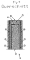
- the composite thermal insulation panel 10 shown in the drawings comprises six vacuum insulation panels 1, which are arranged in a rectangle next to each other, in two rows of three vacuum insulation panels 1.
- the vacuum insulation panels 1 are on both sides of polyurethane foam 2 in a thickness between 5 mm and 50 mm, preferably 10 mm, surrounded or foamed.
- the polyurethane foam 2 is in turn each covered by a preferably vacuum-tight envelope 4, namely an aluminum foil in a thickness of 0.05 mm to 0.5 mm.
- the outer edges 11 of the vacuum insulation panels 1 are surrounded by a pressure-resistant structural foam of polyurethane (construction polyurethane foam) 5.
- the pressure-stable construction foam 5 is seated on the outer edges 11 of the vacuum insulation panels 1. It is surrounded on the outside by a water-vapor-tight high-barrier film 6.
- the high barrier film 6 is U-shaped. It surrounds the outer edges of the pressure-stable construction foam 5, in such a way that the base of the high-barrier film 6 rests against the outer edges or outer surfaces of the pressure-stable construction foam 5 and the legs abut each outside of the polyurethane foam 2.
- the legs of the U-shaped high barrier film 6 abut the aluminum foil 4. They are glued to the aluminum foil 4.
- the envelope namely the aluminum foil 4 is covered on both sides by a further plate 3.
- the further plates 3 are glued to the aluminum foils 4 to the outside. They consist of solid, pressed polyurethane foam in a thickness of 5 mm to 20 mm, preferably 10 mm.
- the further plates improve the mechanical stability of the composite thermal insulation board during further processing and prevent unwanted damage to the vacuum-tight enclosure, namely the aluminum foils 4 and thus ultimately also the vacuum insulation panels 1.
- individual or all vacuum insulation panels 1 are each equipped with a sensor 9. It is the sensor system used in the DE 102 15 213 C1 is described and reference is made. As a sensor or measuring head but also a simplified version can be used, which consists only of a heating foil with two leads. The heating foil is fastened at the location of the vacuum insulation panel 1, at which the internal sensor disk 9 is located. By means of an external evaluation unit connected to the two electrical leads, the power of the heating foil can be monitored during the measuring process and the quality of the vacuum in the vacuum insulating panel, which can also be referred to as a panel, determined therefrom. Thus, after the production of the composite thermal insulation panel 10 and prior to installation in the construction object, the functionality of the vacuum insulation panels can be checked. Furthermore, a subsequent inspection, even years after installation, in principle possible.
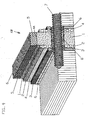
- the composite thermal insulation panel 10 is provided with anchoring elements 7 which allow additional components to be mounted on both sides of the composite thermal insulation panel.
- the recesses 8 may be provided inside or at the edges of the vacuum insulation panels 1. They can be designed oval-shaped. At the locations where the recesses 8 are located in the vacuum insulation panels 1, holes are milled. Subsequently, the anchoring elements 7 are pushed through. In order to prevent an increased moisture passage at the puncture points of the aluminum foil 4, these locations can be sealed with a sealant.
- the heat transfer coefficient is 0.11 W / m 2 K.
- Such a composite thermal insulation panel is suitable for the construction of passive house walls.
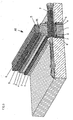
- the composite thermal insulation board 10 is placed with the anchoring elements 7 on a freshly poured concrete slab.
- the upper side of the composite thermal insulation board 10 is also in a concrete formwork filled with concrete.
- the anchor elements 7 enter into an intimate connection with the concrete shells.
- the composite thermal insulation panels 10 are poured out on both sides in a formwork with concrete, the edges can remain free.
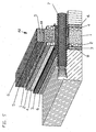
- Fig. 5 is shown a combination of wood material and concrete.
- wrapper 4 and / or high barrier film 6 a vapor-deposited non-woven butyl tape or fabric tape can be used to achieve better mechanical protection with correspondingly higher strength for edge safety.
Landscapes
- Physics & Mathematics (AREA)
- Engineering & Computer Science (AREA)
- Architecture (AREA)
- Acoustics & Sound (AREA)
- Electromagnetism (AREA)
- Civil Engineering (AREA)
- Structural Engineering (AREA)
- Building Environments (AREA)
- Laminated Bodies (AREA)
- Thermal Insulation (AREA)
- Chemical And Physical Treatments For Wood And The Like (AREA)
Abstract
Description
Die Erfindung betrifft eine Verbundwärmedämmplatte nach dem Oberbegriff des Anspruchs 1 und ein Verfahren zur Herstellung einer derartigen Verbundwärmedämmplatte sowie ein Verfahren zum Verarbeiten einer derartigen Verbundwärmedämmplatte.The invention relates to a composite thermal insulation panel according to the preamble of
Im Bauwesen sind tragende Wandelemente bekannt, die als Kern eine Dämmschicht enthalten und die auf beiden Seiten von Betonplatten umgeben sind. Die Betonplatten werden durch Verbundanker sicher zusammengehalten. Weiterhin bekannt sind evakuierte Dämmplatten mit einem Dämmkern aus mikroporöser Kieselsäure und einer Umhüllung aus einer metallisierten Kunststoffolie. Die Vorteile solcher Wandelemente, die einen Dämmkern aus evakuierten Materialien enthalten, sind ein hoher Dämmwert bei einem schlanken Wandaufbau. Mit nur 40 mm Vakuumdämmung aus mikroporöser Kieselsäure läßt sich im Wandaufbau ein U-Wert von 0,11 W/m2K erreichen.In building supporting wall elements are known, which contain a core as an insulating layer and which are surrounded on both sides by concrete slabs. The concrete slabs are securely held together by composite anchors. Also known are evacuated insulation boards with an insulating core of microporous silica and a coating of a metallized plastic film. The advantages of such wall elements, which contain an insulating core of evacuated materials, are a high insulating value with a slim wall construction. With only 40 mm vacuum insulation made of microporous silicic acid, a U value of 0.11 W / m 2 K can be achieved in the wall construction.
Aus der
Sie umfassen in der Regel eine Vakuumdämmplatte aus einem evakuierbaren, porösen Kernmaterial geringer Wärmeleitfähigkeit und einer vakuumdichten Umhüllung, insbesondere einer metallisierten Hochbarrierefolie aus Kunststoff. Als Material für den aus der Vakuumdämmplatte bestehenden Kern kommen mikroporöse Kieselsäurepulver oder offenporige Schäume aus Polyurethan oder Polystyrol in Betracht. Bei mikroporösen Kernen genügt aufgrund ihrer extrem kleinen Porengröße von weniger als einem halben Mikrometer ein Vakuum von etwa 1 bis 10 mbar. Bei offenporigen Schäumen ist es dagegen vorteilhaft oder erforderlich, daß die Gasdrücke aufgrund der gröberen Poren im Bereich von 0,1 bis 1 mbar liegen.As a rule, they comprise a vacuum insulation panel made of an evacuable, porous core material of low thermal conductivity and a vacuum-tight enclosure, in particular a metallized high-barrier film made of plastic. As the material for the existing of the vacuum insulation core core come microporous silica powder or open-celled foams of polyurethane or polystyrene into consideration. For microporous cores, a vacuum of about 1 to 10 mbar is sufficient because of its extremely small pore size of less than half a micron. In the case of open-celled foams, on the other hand, it is advantageous or necessary for the gas pressures to be in the range from 0.1 to 1 mbar due to the coarser pores.
Beim Einsatz von Vakuumdämmplatten im Baubereich ist es allerdings in vielen Fällen wünschenswert oder erforderlich, einige Randbedingungen zu beachten: Die Vakuumdämmplatten dürfen nicht längere Zeit einer erhöhten Feuchtigkeit ausgesetzt werden. Das Verarbeiten der Vakuumdämmplatten ist nur mit großer Vorsicht möglich, da die empfindliche Folie leicht zerstört werden kann. Eine einfache Kontrolle, ob die Vakuumdämmplatte die Herstellung der Bauelemente unbeschadet überstanden hat, ist bisher nicht möglich.When using vacuum insulation panels in construction, however, it is in many cases desirable or necessary to observe some boundary conditions: The vacuum insulation panels must not be exposed to increased humidity for a longer period of time. The processing of the vacuum insulation panels is possible only with great care, as the sensitive film can easily be destroyed. A simple check, whether the vacuum insulation board has survived the production of the components unscathed, is not yet possible.
Rechnerisch sind zwar Nutzungsdauern von 50 Jahren und mehr mit Vakuumdämmplatten im Baubereich möglich, wenn bei der Herstellung entsprechend gute Hochbarrierefolien und mikroporöse, gut getrocknete Dämmkerne verwendet werden. Während der Weiterverarbeitung der Vakuumdämmplatten können jedoch ungewollt Beschädigungen auftreten, die meist nicht einfach erkannt werden können. Eine Kontrolle von Verbundelementen vor dem Einbau in ein Bauobjekt ist daher wünschenswert oder erforderlich.Although useful lives of 50 years and more with vacuum insulation panels in the construction sector are possible, if correspondingly good high-barrier films and microporous, well-dried insulating cores are used in the production. During the further processing of the vacuum insulation panels, however, unintentional damage can occur, which usually can not be detected easily. Control of composite elements prior to installation in a building object is therefore desirable or necessary.
Aus der
Aufgabe der Erfindung ist es, eine verbesserte Verbundwärmeplatte und ein Verfahren zu deren Herstellung und Verarbeitung vorzuschlagen.The object of the invention is to propose an improved composite heat plate and a method for their production and processing.
Erfindungsgemäß wird diese Aufgabe durch eine Verbundwärmedämmplatte mit den Merkmalen des Anspruchs 1 gelöst. Die Verbundwärmedämmplatte umfaßt eine oder mehrere Vakuumdämmplatten und eine Umhüllung. Die Vakuumdämmplatten liegen vorzugsweise nebeneinander. Sie sind zur Bildung eines Vakuums innerhalb der vorzugsweise vakuumdichten Umhüllung evakuiert. Erfindungsgemäß sind die Vakuumdämmplatten beidseitig von Kunststoffschaum umgeben. Bei dem Kunststoffschaum handelt es sich vorzugsweise um Polyurethanschaum. Zur Herstellung der Verbundwärmedämmplatte können die Vakuumdämmplatten beidseitig von Kunststoffschaum bzw. Polyurethanschaum umschäumt werden.According to the invention this object is achieved by a composite thermal insulation board with the features of
Vorteilhafte Weiterbildungen sind in den Unteransprüchen beschrieben.Advantageous developments are described in the subclaims.
Der Kunststoffschaum bzw. Polyurethanschaum ist von einer Aluminiumfolie abgedeckt.The plastic foam or polyurethane foam is covered by an aluminum foil.
Die vakuumdichte Umhüllung bzw. die Aluminiumfolie ist von mindestens einer weiteren Platte abgedeckt. Die weitere Platte besteht vorzugsweise aus Kunststoffschaum. Vorteilhaft ist es, wenn die weitere Platte aus Polyurethanschaum, vorzugsweise gepreßtem Polyurethanschaum; besteht. Sie kann allerdings auch aus einem anderen Werkstoff mit niedriger Wärmeleitfähigkeit hergestellt sein. Die weitere Platte ist vorzugsweise auf die Umhüllung bzw. auf die Aluminiumfolie aufgeklebt.The vacuum-tight envelope or the aluminum foil is covered by at least one further plate. The further plate is preferably made of plastic foam. It is advantageous if the further plate of polyurethane foam, preferably pressed polyurethane foam; consists. However, it can also be made of another material with low thermal conductivity. The further plate is preferably glued to the envelope or on the aluminum foil.
Nach einer weiteren vorteilhaften Weiterbildung sind die Außenkanten der Vakuumdämmplatten von einem druckstabilen Konstruktionsschaum umgeben. Der druckstabile Konstruktionsschaum umgibt vorzugsweise den gesamten umlaufenden Rand der Vakuumdämmplatten. Er weist vorzugsweise die gleiche Stärke auf wie die Vakuumdämmplatten. Vorzugsweise besteht der druckstabile Konstruktionsschaum aus Polyurethan. Zur Herstellung dieser vorteilhaften Weiterbildung kann der druckstabile Konstruktionsschaum vor dem beidseitigen Umschäumen mit Kunststoffschaum im Kantenbereich der Vakuumdämmplatten in vorzugsweise gleicher Stärke als Abstandshalter eingelegt werden.According to a further advantageous development, the outer edges of the vacuum insulation panels are surrounded by a pressure-stable construction foam. The pressure-stable construction foam preferably surrounds the entire peripheral edge of the vacuum insulation panels. It preferably has the same thickness as the vacuum insulation panels. Preferably, the pressure-stable construction foam made of polyurethane. To produce this advantageous development of the pressure-stable construction foam can be inserted before the two-sided foaming with plastic foam in the edge region of the vacuum insulation panels in preferably the same thickness as a spacer.
Eine weitere vorteilhafte Weiterbildung ist dadurch gekennzeichnet, daß die Außenkanten der Vakuumdämmplatten bzw. des druckstabilen Konstruktionsschaums von einer Hochbarrierefolie umgeben sind. Die Hochbarrierefolie ist vorzugsweise aus Kunststoff. Vorzugsweise ist die Hochbarrierefolie wasserdampfdicht. Vorteilhaft ist es, wenn die Hochbarrierefolie U-förmig ausgestaltet ist. Die Hochbarrierefolie wirkt vorzugsweise als Diffusionssperrschicht.A further advantageous development is characterized in that the outer edges of the vacuum insulation panels or the pressure-stable construction foam are surrounded by a high-barrier film. The high barrier film is preferably made of plastic. Preferably, the high barrier film is water vapor tight. It is advantageous if the high barrier film is U-shaped. The high barrier film preferably acts as a diffusion barrier layer.
Vorteilhaft ist es, wenn die Hochbarrierefolie an der Umhüllung bzw. der Aluminiumfolie anliegt. Die Hochbarrierefolie ist vorzugsweise mit der Umhüllung bzw. der Aluminiumfolie verklebt. Vorteilhaft ist es, wenn die Hochbarrierefolie U-förmig ist und die Schenkel der Hochbarrierefolie an der Umhüllung bzw. der Aluminiumfolie anliegen bzw. mit der Umhüllung bzw. der Aluminiumfolie verklebt sind.It is advantageous if the high-barrier film rests against the envelope or the aluminum foil. The high barrier film is preferably glued to the enclosure or the aluminum foil. It is advantageous if the high-barrier film is U-shaped and the legs of the high-barrier film bear against the envelope or the aluminum foil or are glued to the envelope or the aluminum foil.
Zur Herstellung dieser vorteilhaften Weiterbildung kann um die Außenkanten der Vakuumdämmplatten bzw. des druckstabilen Konstruktionsschaums eine vorzugsweise U-förmige Hochbarrierefolie bzw. Hochbarriere-Kunststoffolie herumgelegt werden, vorzugsweise als Diffusionssperrschicht. Die Schenkel der Hochbarrierefolie können mit der Umhüllung bzw. der Aluminiumfolie verklebt werden, so daß der Innenraum gut gegen eindringende Feuchtigkeit geschützt ist.To produce this advantageous development, a preferably U-shaped high-barrier film or high-barrier plastic film can be wrapped around the outer edges of the vacuum insulation panels or of the pressure-stable construction foam, preferably as a diffusion barrier layer. The legs of the high barrier film can be glued to the enclosure or the aluminum foil, so that the interior is well protected against moisture penetration.
An oder in einer oder mehreren oder allen Vakuumdämmplatten kann ein Sensor zur Überprüfung des Gasdrucks angebracht sein. Der Sensor kann über elektrische Zuleitungen ausgelesen werden. Bei dem Sensor kann es sich insbesondere um eine Meßplatte nach der
Eine oder mehrere oder alle Vakuumdämmplatten können Aussparungen aufweisen, in die Verankerungselemente eingesetzt werden oder sind. Zur Herstellung dieser vorteilhaften Weiterbildung können an Stellen, an denen Aussparungen in den Vakuumdämmplatten vorhanden sind, durch die Verbundwärmedämmplatte hindurch Löcher gefräst und dort Verankerungselemente eingesetzt werden. Die Verankerungselemente sind vorzugsweise aus Kohlefaser, Glasfaser oder vergleichbaren Werkstoffen mit niedriger Wärmeleitung wie beispielsweise Wood Composites Plastic hergestellt.One or more or all vacuum insulation panels may have recesses into which anchoring elements are or are used. In order to produce this advantageous development, holes can be milled through the composite thermal insulation board at locations where recesses are present in the vacuum insulation panels, and anchoring elements can be used there. The anchoring elements are preferably made of carbon fiber, glass fiber or similar Low thermal conductivity materials such as Wood Composites Plastic.
Die Verbundwärmedämmplatte mit den Verankerungselementen kann auf eine Betonplatte, insbesondere auf eine frisch gegossene Betonplatte, setzbar oder gesetzt sein. Die andere Seite der Verbundwärmedämmplatte kann ebenfalls mit Beton ausgefüllt werden oder sein, vorzugsweise in einer Betonschalung. Die Verankerungselemente können dabei eine innige Verbindung mit der Betonplatte und/oder dem Beton und/oder der Betonschalung eingehen. Wenn die Verbundwärmedämmplatte mit ihrer unteren Seite auf die vorzugsweise frisch gegossene Betonplatte gesetzt wird, wird ihre obere Seite in der beschriebenen Weise vorzugsweise in einer Betonschalung mit Beton ausgefüllt.The Verbundwärmedämmplatte with the anchoring elements can be placed or set on a concrete slab, in particular on a freshly poured concrete slab. The other side of the composite thermal insulation panel can also be filled with concrete or be, preferably in a concrete formwork. The anchoring elements can enter into an intimate connection with the concrete slab and / or the concrete and / or the concrete formwork. When the composite thermal insulation panel is placed with its lower side on the preferably freshly poured concrete slab, its upper side is preferably filled in the manner described in a concrete formwork with concrete.
Eine weitere vorteilhafte Weiterbildung ist dadurch gekennzeichnet, daß die Verbundwärmedämmplatte mit einer Innenplatte und mit einer Außenplatte verbunden ist. Die Innenplatte und/oder die Außenplatte können aus Beton oder aus Holz oder aus einem Holzwerkstoff, insbesondere aus Dickholz, bestehen. Beispielsweise kann die Innenplatte aus Dickholz und die Außenplatte aus einem Holzwerkstoff bestehen. Es ist allerdings auch möglich, eine Betonplatte mit einer Dickholzplatte bzw. Holzwerkstoffplatte zu kombinieren. Die Verbindung der Verbundwärmedämmplatte mit der Innenplatte und/oder der Außenplatte erfolgt vorzugsweise durch Verkleben. Die Innenplatte und/oder die Außenplatte können mit der Verbundwärmedämmplatte zusätzlich über die aus der Verbundwärmedämmplatte herausstehenden Anker verbunden werden.A further advantageous development is characterized in that the composite heat insulation board is connected to an inner plate and to an outer plate. The inner plate and / or the outer plate may be made of concrete or wood or of a wood material, in particular of thick wood. For example, the inner panel made of thick wood and the outer panel made of a wood material. However, it is also possible to combine a concrete slab with a thick wood slab or wood-based slab. The compound of the composite thermal insulation board with the inner plate and / or the outer plate is preferably carried out by gluing. The inner panel and / or the outer panel may be additionally connected to the composite thermal insulation panel via the anchors protruding from the composite thermal insulation panel.
Ein Verfahren zur Herstellung einer erfindungsgemäßen Verbundwärmedämmplatte ist erfindungsgemäß dadurch gekennzeichnet, daß eine oder mehrere evakuierte Vakuumdämmplatten beidseitig von Kunststoffschaum, vorzugsweise Polyurethanschaum, umschäumt werden.A method for producing a composite thermal insulation panel according to the invention is characterized in that one or more evacuated vacuum insulation panels on both sides of plastic foam, preferably polyurethane foam, are foamed.
Ein Verfahren zum Verarbeiten einer erfindungsgemäßen Verbundwärmedämmplatte ist erfindungsgemäß dadurch gekennzeichnet, daß die Verbundwärmedämmplatte auf eine frisch gegossene Betonplatte gesetzt wird. Die andere bzw. obere Seite der Verbundwärmedämmplatte wird vorzugsweise mit Beton, vorzugsweise in einer Betonschalung, ausgefüllt. Vorteilhaft ist es, wenn die Verbundwärmedämmplatte Verankerungselemente aufweist, die eine innige Verbindung mit dem Beton bzw. den Betonschalungen eingehen.A method for processing a composite thermal insulation panel according to the invention is characterized in accordance with the invention in that the composite thermal insulation panel is placed on a freshly poured concrete slab. The other or upper side of the composite thermal insulation panel is preferably filled with concrete, preferably in a concrete formwork. It is advantageous if the composite thermal insulation board has anchoring elements which form an intimate connection with the concrete or the concrete formwork.
Durch die Erfindung wird eine Verbundwärmedämmplatte mit einer oder mehreren Vakuumdämmplatten als Kern und einer beidseitigen Umschäumung mit Kunststoffschaum, vorzugsweise Polyurethanschaum, geschaffen. Durch die erfindungsgemäße Ausgestaltung kann ein zusätzlicher Feuchtigkeitsschutz erreicht werden. Ferner ist es möglich, die Verbundwärmedämmplatte mit tragenden Platten aus Beton und/oder Holzwerkstoffen zu kombinieren. Schließlich wird eine integrierte Kontrolle der Güte der Vakuumdämmplatten ermöglicht.The invention provides a composite thermal insulation panel with one or more vacuum insulation panels as the core and a foam coating on both sides with plastic foam, preferably polyurethane foam. The inventive design, an additional moisture protection can be achieved. Furthermore, it is possible to combine the composite thermal insulation panel with load-bearing concrete and / or wooden panels. Finally, an integrated control of the quality of the vacuum insulation panels is made possible.
Ausführungsbeispiele der Erfindung werden nachstehend anhand der beigefügten Zeichnung im einzelnen erläutert. In der Zeichnung zeigt
- Fig. 1
- eine Verbundwärmedämmplatte in einem Querschnitt,
- Fig. 2
- die Verbundwärmedämmplatte gemäß
Fig. 1 in einer Draufsicht, - Fig. 3
- die Verbundwärmedämmplatte gemäß
Fig. 1 und2 im eingebauten Zustand in einer perspektivischen Ansicht, - Fig. 4
- eine Abwandlung des Einbaus der Verbundwärmedämmplatte gemäß
Fig. 1 in einer perspektivischen Ansicht undbis 3 - Fig. 5
- eine weitere Abwandlung des Einbaus der Verbundwärmedämmplatte gemäß
Fig. 1 in einer perspektivischen Ansicht.bis 4
- Fig. 1
- a composite thermal insulation panel in a cross section,
- Fig. 2
- the composite thermal insulation board according to
Fig. 1 in a plan view, - Fig. 3
- the composite thermal insulation board according to
Fig. 1 and2 when installed in a perspective view, - Fig. 4
- a modification of the installation of the composite thermal insulation board according to
Fig. 1 to 3 in a perspective view and - Fig. 5
- a further modification of the installation of the composite thermal insulation board according to
Fig. 1 to 4 in a perspective view.
Die in den Zeichnungsfiguren gezeigte Verbundwärmedämmplatte 10 umfaßt sechs Vakuumdämmplatten 1, die in einem Rechteck nebeneinander angeordnet sind, und zwar in zwei Reihen zu je drei Vakuumdämmplatten 1. Die Vakuumdämmplatten 1 sind beidseitig von Polyurethanschaum 2 in einer Stärke zwischen 5 mm und 50 mm, bevorzugt 10 mm, umgeben bzw. umschäumt. Der Polyurethanschaum 2 ist seinerseits jeweils von einer vorzugsweise vakuumdichten Umhüllung 4, nämlich einer Aluminiumfolie in einer Stärke von 0,05 mm bis 0,5 mm abgedeckt.The composite
Die Außenkanten 11 der Vakuumdämmplatten 1 sind von einem druckstabilen Konstruktionsschaum aus Polyurethan (Konstruktions-Polyurethanschaum) 5 umgeben. Der druckstabile Konstruktionsschaum 5 sitzt an den Außenkanten 11 der Vakuumdämmplatten 1. Er ist nach außen hin von einer wasserdampfdichten Hochbarrierefolie 6 umgeben. Die Hochbarrierefolie 6 ist U-förmig. Sie umgibt die Außenkanten des druckstabilen Konstruktionsschaums 5, und zwar derart, daß die Basis der Hochbarrierefolie 6 an den Außenkanten bzw. Außenflächen des druckstabilen Konstruktionsschaums 5 anliegt und die Schenkel jeweils außen an dem Polyurethanschaum 2 anliegen. Die Schenkel der U-förmigen Hochbarrierefolie 6 liegen an der Aluminiumfolie 4 an. Sie sind mit der Aluminiumfolie 4 verklebt. Die Aluminiumfolien 4 und die Hochbarrierefolien 6, die zusammen die Umhüllung bilden, verhindern, daß Feuchtigkeit an die Vakuumdämmplatten 1 gelangt. Diese Feuchtigkeit könnte ansonsten auf Dauer die Funktion der Vakuumdämmplatten 1 schädigen und deren Lebensdauer verkürzen.The outer edges 11 of the
Die Umhüllung, nämlich die Aluminiumfolie 4, ist beidseitig von einer weiteren Platte 3 abgedeckt. Die weiteren Platten 3 sind auf die Aluminiumfolien 4 nach außen hin aufgeklebt. Sie bestehen aus massivem, gepreßtem Polyurethanschaum in einer Stärke von 5 mm bis 20 mm, bevorzugt 10 mm. Die weiteren Platten verbessern die mechanische Stabilität der Verbundwärmedämmplatte beim Weiterverarbeiten und verhindern eine ungewollte Beschädigung der vakuumdichten Umhüllung, nämlich der Aluminiumfolien 4 und damit letztlich auch der Vakuumdämmplatten 1.The envelope, namely the
Um die Vakuumdämmplatten 1 auch in ihrem Verbund in der Verbundwärmedämmplatte 10 auf ihre Funktionsfähigkeit prüfen zu können, werden einzelne oder alle Vakuumdämmplatten 1 mit jeweils einem Sensor 9 ausgerüstet. Es handelt sich um das Sensorsystem, das in der
Die Verbundwärmedämmplatte 10 ist mit Verankerungselementen 7 ausgestattet, die es ermöglichen, zusätzliche Bauelemente auf beiden Seiten der Verbundwärmedämmplatte anzubringen. Hierzu weisen die Vakuumdämmplatten 1 Aussparungen 8 auf. Die Aussparungen 8 können im Inneren oder an den Rändern der Vakuumdämmplatten 1 vorgesehen sein. Sie können ovalförmig ausgestaltet sein. An den Stellen, an denen sich die Aussparungen 8 in den Vakuumdämmplatten 1 befinden, werden Löcher gefräst. Anschließend werden die Verankerungselemente 7 durchgesteckt. Um an den Durchstoßstellen der Aluminiumfolie 4 einen erhöhten Feuchtedurchgang zu unterbinden, können diese Stellen mit einem Dichtmittel abgedichtet werden. Bei einer Stärke der Verbundwärmedämmplatte 10 von 80 mm beträgt der Wärmedurchgangskoeffizient 0,11 W/m2K. Eine derartige Verbundwärmedämmplatte ist für die Konstruktion von Passivhauswänden geeignet.The composite
Bei der Ausführungsform nach
Es ist allerdings auch möglich, wie in
In
Als Umhüllung 4 und/oder Hochbarrierefolie 6 können auch ein bedampftes Vliesbuthylband oder Gewebeband verwendet werden, um einen besseren mechanischen Schutz mit entsprechend höherer Festigkeit für die Kantensicherheit zu erreichen.As
Claims (14)
- Composite heat-insulating board (10) having one or more vacuum insulation boards (1) and a casing (4, 6), the vacuum insulation boards (1) being surrounded on both sides by plastic foam (2),
characterized
in that the plastic foam (2) is covered by the casing configured as an aluminium foil (4),
and in that the casing (4) is covered by a further board (3). - Composite heat-insulating board according to Claim 1, characterized in that the plastic foam is polyurethane foam (2).
- Composite heat-insulating board according to Claim 1 or 2, characterized in that the outer edges (11) of the vacuum insulation boards (1) are surrounded by a pressure-stable construction foam (5).
- Composite heat-insulating board according to one of the preceding claims, characterized in that the outer edges of the vacuum insulation boards (1) or of the pressure-stable construction foam (5) are surrounded by a high-barrier foil (6).
- Composite heat-insulating board according to Claim 4, characterized in that the high-barrier foil (6) bears against the casing or the aluminium foil (4).
- Composite heat-insulating board according to one of the preceding claims, characterized in that on or in one or more or all of the vacuum insulation boards (1), a sensor (9) is fitted for monitoring the gas pressure.
- Composite heat-insulating board according to one of the preceding claims, characterized in that one or more or all of the vacuum insulation boards (1) have cavities (8), in which anchoring elements (7) are inserted.
- Composite heat-insulating board according to Claim 7, characterized in that the composite heat-insulating board (10) with the anchoring elements (7) is placeable or placed onto a concrete slab.
- Composite heat-insulating board according to Claim 8, characterized in that the other side of the composite heat-insulating board (10) is full of concrete.
- Composite heat-insulating board according to one of the preceding claims, characterized in that the composite heat-insulating board (10) is connected to an inner board and to an outer board.
- Method for producing a composite heat-insulating board (10) according to one of Claims 1 to 10,
characterized in that
one or more evacuated vacuum insulation boards (1) are encased on both sides by plastic foam (2), in that the plastic foam (2) is covered by an aluminium foil (4), and in that the casing (4) is covered by a further board (3). - Method for treating a composite heat-insulating board (10) according to one of Claims 1 to 10,
characterized
in that the composite heat-insulating board (10) is placed onto a freshly cast concrete slab. - Method according to Claim 12, characterized in that the other side of the composite heat-insulating board (10) is filled with concrete.
- Method according to Claim 12 or 13, characterized in that the composite heat-insulating board (10) has anchoring elements (7), which enter into an intimate connection with the concrete.
Applications Claiming Priority (2)
| Application Number | Priority Date | Filing Date | Title |
|---|---|---|---|
| DE10359005A DE10359005A1 (en) | 2003-12-15 | 2003-12-15 | Composite thermal insulation board |
| DE10359005 | 2003-12-15 |
Publications (3)
| Publication Number | Publication Date |
|---|---|
| EP1544367A2 EP1544367A2 (en) | 2005-06-22 |
| EP1544367A3 EP1544367A3 (en) | 2006-06-14 |
| EP1544367B1 true EP1544367B1 (en) | 2009-02-18 |
Family
ID=34485417
Family Applications (1)
| Application Number | Title | Priority Date | Filing Date |
|---|---|---|---|
| EP04029733A Expired - Lifetime EP1544367B1 (en) | 2003-12-15 | 2004-12-15 | Laminated heat insulating panel |
Country Status (3)
| Country | Link |
|---|---|
| EP (1) | EP1544367B1 (en) |
| AT (1) | ATE423243T1 (en) |
| DE (2) | DE10359005A1 (en) |
Cited By (1)
| Publication number | Priority date | Publication date | Assignee | Title |
|---|---|---|---|---|
| DE102010018515A1 (en) | 2009-04-29 | 2010-11-18 | Haacke Treuhand Gmbh | Wall element for thermal insulation of building facades, and for use in product line, and hence has outer layer facing outer chamber, where surface is designed to face towards building facade |
Families Citing this family (29)
| Publication number | Priority date | Publication date | Assignee | Title |
|---|---|---|---|---|
| DE102005027972A1 (en) * | 2005-06-16 | 2006-12-21 | Variotec Sandwichelemente Gmbh & Co. Kg | wall element |
| DE102005027973A1 (en) * | 2005-06-16 | 2006-12-21 | Variotec Sandwichelemente Gmbh & Co. Kg | wall element |
| SE530643C2 (en) * | 2006-02-22 | 2008-07-29 | Maxit Group Ab | Heat insulation plate, heat insulated construction and method of construction of such construction |
| DE102006039621A1 (en) * | 2006-08-24 | 2008-02-28 | Porextherm-Dämmstoffe Gmbh | Vacuum insulation panel with bushing |
| DE202008002492U1 (en) | 2008-02-22 | 2009-06-25 | Variotec Sandwichelemente Gmbh & Co. Kg | Composite thermal insulation panel and composite thermal insulation system |
| DE202008002491U1 (en) | 2008-02-22 | 2009-06-25 | Variotec Sandwichelemente Gmbh & Co. Kg | Composite thermal insulation board |
| DE202008002490U1 (en) | 2008-02-22 | 2009-06-25 | Variotec Sandwichelemente Gmbh & Co. Kg | Composite thermal insulation panel, in particular for the insulation of external blinds |
| DE102008021305A1 (en) * | 2008-04-22 | 2009-11-05 | Gonon Isolation Ag (Sa) | Method for producing a thermal insulation board |
| DE102008064572A1 (en) | 2008-12-30 | 2010-07-08 | Alsecco Gmbh & Co Kg | Multilayered thermal insulation board and method for building a thermal insulation facade |
| DE102009000984A1 (en) * | 2009-02-18 | 2010-08-19 | Vacu Team Gmbh | Building element e.g. wall element, has intermediate space formed between plates, where one of plate is formed as support plate, and intermediate space is formed as gas-tight hollow body |
| DE102009013888A1 (en) | 2009-03-19 | 2010-09-23 | Variotec Sandwichelemente Gmbh & Co. Kg | Vacuum insulation panel for use in composite heat insulating panel of building, has vacuum-tight enclosure comprising high barrier film and shrink film, where high barrier film comprises sealing layer made of plastic such as polyethylene |
| DE102009021813A1 (en) * | 2009-04-02 | 2010-10-07 | Ewald Dörken Ag | Insulating agent for the production of a thermal insulation system, thermal insulation system and building envelope with a thermal insulation system |
| WO2010121580A1 (en) * | 2009-04-23 | 2010-10-28 | Technische Universität Dortmund | Vacuum insulation element having ceramic cover layers for use in a building shell |
| AT12147U1 (en) * | 2009-06-10 | 2011-11-15 | Monai Bernhard Dipl Ing | WALL ELEMENT |
| EP2657425B1 (en) * | 2012-04-23 | 2017-08-02 | STO SE & Co. KGaA | Heat insulation compound panel and heat insulation method for a window or door embrasure in the outer wall of a building |
| FR2990223B1 (en) * | 2012-05-03 | 2015-10-30 | Saint Gobain Weber | THERMALLY INSULATING CONSTRUCTION BLOCK |
| DE202013005599U1 (en) * | 2013-06-20 | 2014-09-22 | Variotec Gmbh & Co. Kg | Wall element, façade element and facade with a vacuum insulation panel |
| DE202013104133U1 (en) | 2013-09-11 | 2013-10-15 | Michael Sorge | Polymer material based on renewable raw materials |
| CN103660446B (en) * | 2013-12-11 | 2016-04-27 | 华南农业大学 | Refrigerated Transport compartment, composite insulation boards and manufacture method thereof |
| DE102014007705A1 (en) | 2014-05-28 | 2015-12-03 | Va-Q-Tec Ag | Composite thermal insulation board |
| DE202014004359U1 (en) | 2014-05-28 | 2015-08-31 | Va-Q-Tec Ag | Composite thermal insulation board |
| GB201415412D0 (en) * | 2014-08-30 | 2014-10-15 | Robinson Nigel | Insulated conservatory roof panel |
| DE102014016709A1 (en) * | 2014-11-13 | 2016-05-19 | Fkn Fassaden Gmbh & Co.Kg | Facade system for the renovation of old buildings with refractory façade elements of high heat - insulation effect on uneven ground of the building wall and method for its production |
| US10603865B2 (en) * | 2014-12-25 | 2020-03-31 | AGC Inc. | Insulating member and its attaching method |
| DE202015005010U1 (en) | 2015-07-17 | 2015-08-12 | Va-Q-Tec Ag | Wall, door or lid element for an insulating container |
| EP3141370B1 (en) * | 2015-09-11 | 2023-05-24 | Mitsubishi Electric Corporation | Method for producing composite thermal insulator, method for producing water heater, and composite thermal insulator |
| DE102015015689A1 (en) * | 2015-11-30 | 2017-06-01 | Gonon Isolation Ag (Sa) | Thermal insulation board and method for laying the thermal insulation board |
| DE102015225714A1 (en) * | 2015-12-17 | 2017-06-22 | Evonik Degussa Gmbh | Insulation composite with diffusion-open edge bond |
| EP4025522A4 (en) | 2019-09-05 | 2023-12-27 | Cold Chain Technologies, LLC | SHIPPING SYSTEM FOR TEMPERATURE SENSITIVE MATERIALS |
Family Cites Families (10)
| Publication number | Priority date | Publication date | Assignee | Title |
|---|---|---|---|---|
| US3264165A (en) * | 1964-11-25 | 1966-08-02 | Gen Motors Corp | Insulating means |
| US3993811A (en) * | 1974-08-15 | 1976-11-23 | The Dow Chemical Company | Thermal insulating panel for use in an insulative container and method of making said panel |
| US4284674A (en) * | 1979-11-08 | 1981-08-18 | American Can Company | Thermal insulation |
| US5500305A (en) * | 1990-09-24 | 1996-03-19 | Aladdin Industries, Inc. | Vacuum insulated panel and method of making a vacuum insulated panel |
| DE19915456A1 (en) * | 1999-04-01 | 2000-10-05 | Bsh Bosch Siemens Hausgeraete | Vacuum insulated wall, e.g. a refrigerator housing or door, has inner and outer thermoplastic linings with a water vapor and gas permeability reducing system |
| DE19923057A1 (en) * | 1999-05-20 | 2000-11-23 | Schueco Int Kg | Heat insulating panel for windows, doors and building faces houses in its interior at least one insulating unit in a metal-coated metal cover whose interior is subjected to vacuum before its closure by welding |
| DE10058566C2 (en) * | 2000-08-03 | 2002-10-31 | Va Q Tec Ag | Foil-wrapped, evacuated thermal insulation body and manufacturing process for it |
| DE10213058A1 (en) * | 2001-03-26 | 2002-10-17 | Joerg Ortjohann | Thermal insulation, for a building, has a super-insulation material evacuated within a film shrouding to be butted against other insulation sections, with an uninterrupted lamination over them on one side |
| WO2003002828A1 (en) * | 2001-06-29 | 2003-01-09 | Sager Ag | Vacuum insulation panel |
| DE10215213C1 (en) * | 2002-04-06 | 2003-09-11 | Va Q Tec Ag | Gas pressure in sheet-enveloped evacuated thermal insulation panel determining device, has built-in covered metal plate acting as thermal reservoir |
-
2003
- 2003-12-15 DE DE10359005A patent/DE10359005A1/en not_active Ceased
-
2004
- 2004-12-15 DE DE502004009007T patent/DE502004009007D1/en not_active Expired - Lifetime
- 2004-12-15 AT AT04029733T patent/ATE423243T1/en active
- 2004-12-15 EP EP04029733A patent/EP1544367B1/en not_active Expired - Lifetime
Cited By (1)
| Publication number | Priority date | Publication date | Assignee | Title |
|---|---|---|---|---|
| DE102010018515A1 (en) | 2009-04-29 | 2010-11-18 | Haacke Treuhand Gmbh | Wall element for thermal insulation of building facades, and for use in product line, and hence has outer layer facing outer chamber, where surface is designed to face towards building facade |
Also Published As
| Publication number | Publication date |
|---|---|
| DE10359005A1 (en) | 2005-07-14 |
| ATE423243T1 (en) | 2009-03-15 |
| EP1544367A3 (en) | 2006-06-14 |
| EP1544367A2 (en) | 2005-06-22 |
| DE502004009007D1 (en) | 2009-04-02 |
Similar Documents
| Publication | Publication Date | Title |
|---|---|---|
| EP1544367B1 (en) | Laminated heat insulating panel | |
| EP2204513A2 (en) | Multi-layer heat insulating board and method for building a heat insulated facade | |
| CH631227A5 (en) | Cladding panel | |
| EP2460945A2 (en) | Thermal insulation board with embedded low thermal conductivity thermal insulation elements and assembly kit for same | |
| DE10147409B4 (en) | Heat-insulating, load-bearing component and method for its production | |
| DE202010001167U1 (en) | Plate-shaped insulation layer for a wall and plate-shaped wall element | |
| EP0947638B1 (en) | Insulation panel for use on exterior facades of houses | |
| DE10250665A1 (en) | wall system | |
| DE3603069A1 (en) | Process for producing dimensionally stable laminated elements and laminated elements produced by the process | |
| DE2507244B1 (en) | Translucent fire protection composite pane, consisting of at least two glass plates and an intermediate layer made of a material that expands when exposed to heat | |
| EP1734195B1 (en) | Wall element | |
| EP3120985A1 (en) | Method for producing an insulation element as well as a corresponding insulation element | |
| EP1734197B1 (en) | Wall element comprising vacuum insulation panel arranged between two prefabricated concrete parts | |
| EP1767739A2 (en) | Door with frame and insulating core | |
| DE202010001216U1 (en) | External wall insulation system | |
| WO2016142480A1 (en) | Insulating element | |
| DE102010018515A1 (en) | Wall element for thermal insulation of building facades, and for use in product line, and hence has outer layer facing outer chamber, where surface is designed to face towards building facade | |
| DE102009003749B4 (en) | Composite material for creating a fire protection joint | |
| DE29922190U1 (en) | Insulation board element for wall cladding | |
| DE10232446A1 (en) | Compound walling brick has two brick layers with a central insulating layer held together by bands or clips | |
| DE20114321U1 (en) | Sandwich panel, especially for creating so-called room cells | |
| EP1734194A2 (en) | Wall element and associated compensation element | |
| DE102005032557A1 (en) | Component for building structures comprises an insulating plate made from a foamed polymer with a concrete layer placed on the plate as lost shell | |
| DE102015112154A1 (en) | Method for producing an insulating element and a corresponding insulating element | |
| DE202004017115U1 (en) | Heat insulation plate (1) for buildings comprises partially overlapping moldings which consist of a porous heat insulation material, are accommodated in airtight covers, and are embedded in a heat insulation cover layer |
Legal Events
| Date | Code | Title | Description |
|---|---|---|---|
| PUAI | Public reference made under article 153(3) epc to a published international application that has entered the european phase |
Free format text: ORIGINAL CODE: 0009012 |
|
| AK | Designated contracting states |
Kind code of ref document: A2 Designated state(s): AT BE BG CH CY CZ DE DK EE ES FI FR GB GR HU IE IS IT LI LT LU MC NL PL PT RO SE SI SK TR |
|
| AX | Request for extension of the european patent |
Extension state: AL BA HR LV MK YU |
|
| PUAL | Search report despatched |
Free format text: ORIGINAL CODE: 0009013 |
|
| AK | Designated contracting states |
Kind code of ref document: A3 Designated state(s): AT BE BG CH CY CZ DE DK EE ES FI FR GB GR HU IE IS IT LI LT LU MC NL PL PT RO SE SI SK TR |
|
| AX | Request for extension of the european patent |
Extension state: AL BA HR LV MK YU |
|
| 17P | Request for examination filed |
Effective date: 20061103 |
|
| AKX | Designation fees paid |
Designated state(s): AT BE BG CH CY CZ DE DK EE ES FI FR GB GR HU IE IS IT LI LT LU MC NL PL PT RO SE SI SK TR |
|
| 17Q | First examination report despatched |
Effective date: 20071017 |
|
| GRAP | Despatch of communication of intention to grant a patent |
Free format text: ORIGINAL CODE: EPIDOSNIGR1 |
|
| GRAS | Grant fee paid |
Free format text: ORIGINAL CODE: EPIDOSNIGR3 |
|
| GRAA | (expected) grant |
Free format text: ORIGINAL CODE: 0009210 |
|
| AK | Designated contracting states |
Kind code of ref document: B1 Designated state(s): AT BE BG CH CY CZ DE DK EE ES FI FR GB GR HU IE IS IT LI LT LU MC NL PL PT RO SE SI SK TR |
|
| REG | Reference to a national code |
Ref country code: GB Ref legal event code: FG4D Free format text: NOT ENGLISH |
|
| REG | Reference to a national code |
Ref country code: CH Ref legal event code: EP Ref country code: CH Ref legal event code: NV Representative=s name: BOVARD AG PATENTANWAELTE |
|
| REG | Reference to a national code |
Ref country code: IE Ref legal event code: FG4D Free format text: LANGUAGE OF EP DOCUMENT: GERMAN |
|
| REF | Corresponds to: |
Ref document number: 502004009007 Country of ref document: DE Date of ref document: 20090402 Kind code of ref document: P |
|
| PG25 | Lapsed in a contracting state [announced via postgrant information from national office to epo] |
Ref country code: LT Free format text: LAPSE BECAUSE OF FAILURE TO SUBMIT A TRANSLATION OF THE DESCRIPTION OR TO PAY THE FEE WITHIN THE PRESCRIBED TIME-LIMIT Effective date: 20090218 Ref country code: FI Free format text: LAPSE BECAUSE OF FAILURE TO SUBMIT A TRANSLATION OF THE DESCRIPTION OR TO PAY THE FEE WITHIN THE PRESCRIBED TIME-LIMIT Effective date: 20090218 Ref country code: ES Free format text: LAPSE BECAUSE OF FAILURE TO SUBMIT A TRANSLATION OF THE DESCRIPTION OR TO PAY THE FEE WITHIN THE PRESCRIBED TIME-LIMIT Effective date: 20090529 Ref country code: SI Free format text: LAPSE BECAUSE OF FAILURE TO SUBMIT A TRANSLATION OF THE DESCRIPTION OR TO PAY THE FEE WITHIN THE PRESCRIBED TIME-LIMIT Effective date: 20090218 |
|
| PG25 | Lapsed in a contracting state [announced via postgrant information from national office to epo] |
Ref country code: PL Free format text: LAPSE BECAUSE OF FAILURE TO SUBMIT A TRANSLATION OF THE DESCRIPTION OR TO PAY THE FEE WITHIN THE PRESCRIBED TIME-LIMIT Effective date: 20090218 Ref country code: SE Free format text: LAPSE BECAUSE OF FAILURE TO SUBMIT A TRANSLATION OF THE DESCRIPTION OR TO PAY THE FEE WITHIN THE PRESCRIBED TIME-LIMIT Effective date: 20090518 Ref country code: IS Free format text: LAPSE BECAUSE OF FAILURE TO SUBMIT A TRANSLATION OF THE DESCRIPTION OR TO PAY THE FEE WITHIN THE PRESCRIBED TIME-LIMIT Effective date: 20090618 |
|
| PG25 | Lapsed in a contracting state [announced via postgrant information from national office to epo] |
Ref country code: PT Free format text: LAPSE BECAUSE OF FAILURE TO SUBMIT A TRANSLATION OF THE DESCRIPTION OR TO PAY THE FEE WITHIN THE PRESCRIBED TIME-LIMIT Effective date: 20090727 Ref country code: EE Free format text: LAPSE BECAUSE OF FAILURE TO SUBMIT A TRANSLATION OF THE DESCRIPTION OR TO PAY THE FEE WITHIN THE PRESCRIBED TIME-LIMIT Effective date: 20090218 Ref country code: CZ Free format text: LAPSE BECAUSE OF FAILURE TO SUBMIT A TRANSLATION OF THE DESCRIPTION OR TO PAY THE FEE WITHIN THE PRESCRIBED TIME-LIMIT Effective date: 20090218 Ref country code: DK Free format text: LAPSE BECAUSE OF FAILURE TO SUBMIT A TRANSLATION OF THE DESCRIPTION OR TO PAY THE FEE WITHIN THE PRESCRIBED TIME-LIMIT Effective date: 20090218 |
|
| PG25 | Lapsed in a contracting state [announced via postgrant information from national office to epo] |
Ref country code: SK Free format text: LAPSE BECAUSE OF FAILURE TO SUBMIT A TRANSLATION OF THE DESCRIPTION OR TO PAY THE FEE WITHIN THE PRESCRIBED TIME-LIMIT Effective date: 20090218 Ref country code: RO Free format text: LAPSE BECAUSE OF FAILURE TO SUBMIT A TRANSLATION OF THE DESCRIPTION OR TO PAY THE FEE WITHIN THE PRESCRIBED TIME-LIMIT Effective date: 20090218 |
|
| PLBE | No opposition filed within time limit |
Free format text: ORIGINAL CODE: 0009261 |
|
| STAA | Information on the status of an ep patent application or granted ep patent |
Free format text: STATUS: NO OPPOSITION FILED WITHIN TIME LIMIT |
|
| 26N | No opposition filed |
Effective date: 20091119 |
|
| PG25 | Lapsed in a contracting state [announced via postgrant information from national office to epo] |
Ref country code: BG Free format text: LAPSE BECAUSE OF FAILURE TO SUBMIT A TRANSLATION OF THE DESCRIPTION OR TO PAY THE FEE WITHIN THE PRESCRIBED TIME-LIMIT Effective date: 20090518 |
|
| PGFP | Annual fee paid to national office [announced via postgrant information from national office to epo] |
Ref country code: IE Payment date: 20091230 Year of fee payment: 6 |
|
| PG25 | Lapsed in a contracting state [announced via postgrant information from national office to epo] |
Ref country code: MC Free format text: LAPSE BECAUSE OF NON-PAYMENT OF DUE FEES Effective date: 20100701 |
|
| PG25 | Lapsed in a contracting state [announced via postgrant information from national office to epo] |
Ref country code: GR Free format text: LAPSE BECAUSE OF FAILURE TO SUBMIT A TRANSLATION OF THE DESCRIPTION OR TO PAY THE FEE WITHIN THE PRESCRIBED TIME-LIMIT Effective date: 20090519 |
|
| PGFP | Annual fee paid to national office [announced via postgrant information from national office to epo] |
Ref country code: AT Payment date: 20101221 Year of fee payment: 7 |
|
| PGFP | Annual fee paid to national office [announced via postgrant information from national office to epo] |
Ref country code: LU Payment date: 20101224 Year of fee payment: 7 |
|
| PGFP | Annual fee paid to national office [announced via postgrant information from national office to epo] |
Ref country code: IT Payment date: 20101216 Year of fee payment: 7 Ref country code: GB Payment date: 20101224 Year of fee payment: 7 |
|
| REG | Reference to a national code |
Ref country code: CH Ref legal event code: PFA Owner name: VARIOTEC SANDWICHELEMENTE GMBH & CO. KG Free format text: VARIOTEC SANDWICHELEMENTE GMBH & CO. KG#WEISSMARTER STRASSE 3#92318 NEUMARKT (DE) $ VA-Q-TEC AG#KARL-FERDINAND-BRAUN-STRASSE 7#97080 WUERZBURG (DE) -TRANSFER TO- VARIOTEC SANDWICHELEMENTE GMBH & CO. KG#WEISSMARTER STRASSE 3#92318 NEUMARKT (DE) $ VA-Q-TEC AG#KARL-FERDINAND-BRAUN-STRASSE 7#97080 WUERZBURG (DE) |
|
| PG25 | Lapsed in a contracting state [announced via postgrant information from national office to epo] |
Ref country code: HU Free format text: LAPSE BECAUSE OF FAILURE TO SUBMIT A TRANSLATION OF THE DESCRIPTION OR TO PAY THE FEE WITHIN THE PRESCRIBED TIME-LIMIT Effective date: 20090819 |
|
| PG25 | Lapsed in a contracting state [announced via postgrant information from national office to epo] |
Ref country code: TR Free format text: LAPSE BECAUSE OF FAILURE TO SUBMIT A TRANSLATION OF THE DESCRIPTION OR TO PAY THE FEE WITHIN THE PRESCRIBED TIME-LIMIT Effective date: 20090218 |
|
| PG25 | Lapsed in a contracting state [announced via postgrant information from national office to epo] |
Ref country code: CY Free format text: LAPSE BECAUSE OF FAILURE TO SUBMIT A TRANSLATION OF THE DESCRIPTION OR TO PAY THE FEE WITHIN THE PRESCRIBED TIME-LIMIT Effective date: 20090218 |
|
| PG25 | Lapsed in a contracting state [announced via postgrant information from national office to epo] |
Ref country code: IE Free format text: LAPSE BECAUSE OF NON-PAYMENT OF DUE FEES Effective date: 20101215 |
|
| PGFP | Annual fee paid to national office [announced via postgrant information from national office to epo] |
Ref country code: CH Payment date: 20111222 Year of fee payment: 8 Ref country code: NL Payment date: 20111228 Year of fee payment: 8 |
|
| PGFP | Annual fee paid to national office [announced via postgrant information from national office to epo] |
Ref country code: BE Payment date: 20111230 Year of fee payment: 8 |
|
| GBPC | Gb: european patent ceased through non-payment of renewal fee |
Effective date: 20111215 |
|
| PG25 | Lapsed in a contracting state [announced via postgrant information from national office to epo] |
Ref country code: GB Free format text: LAPSE BECAUSE OF NON-PAYMENT OF DUE FEES Effective date: 20111215 |
|
| PG25 | Lapsed in a contracting state [announced via postgrant information from national office to epo] |
Ref country code: LU Free format text: LAPSE BECAUSE OF NON-PAYMENT OF DUE FEES Effective date: 20111215 |
|
| BERE | Be: lapsed |
Owner name: VA-Q-TEC A.G. Effective date: 20121231 Owner name: VARIOTEC SANDWICHELEMENTE G.M.B.H. & CO. KG Effective date: 20121231 |
|
| REG | Reference to a national code |
Ref country code: NL Ref legal event code: V1 Effective date: 20130701 |
|
| REG | Reference to a national code |
Ref country code: CH Ref legal event code: PL |
|
| REG | Reference to a national code |
Ref country code: AT Ref legal event code: MM01 Ref document number: 423243 Country of ref document: AT Kind code of ref document: T Effective date: 20121215 |
|
| PG25 | Lapsed in a contracting state [announced via postgrant information from national office to epo] |
Ref country code: BE Free format text: LAPSE BECAUSE OF NON-PAYMENT OF DUE FEES Effective date: 20121231 |
|
| PG25 | Lapsed in a contracting state [announced via postgrant information from national office to epo] |
Ref country code: CH Free format text: LAPSE BECAUSE OF NON-PAYMENT OF DUE FEES Effective date: 20121231 Ref country code: LI Free format text: LAPSE BECAUSE OF NON-PAYMENT OF DUE FEES Effective date: 20121231 Ref country code: AT Free format text: LAPSE BECAUSE OF NON-PAYMENT OF DUE FEES Effective date: 20121215 Ref country code: NL Free format text: LAPSE BECAUSE OF NON-PAYMENT OF DUE FEES Effective date: 20130701 |
|
| PG25 | Lapsed in a contracting state [announced via postgrant information from national office to epo] |
Ref country code: IT Free format text: LAPSE BECAUSE OF NON-PAYMENT OF DUE FEES Effective date: 20121215 |
|
| PGFP | Annual fee paid to national office [announced via postgrant information from national office to epo] |
Ref country code: DE Payment date: 20131230 Year of fee payment: 10 |
|
| PGFP | Annual fee paid to national office [announced via postgrant information from national office to epo] |
Ref country code: FR Payment date: 20131220 Year of fee payment: 10 |
|
| REG | Reference to a national code |
Ref country code: DE Ref legal event code: R119 Ref document number: 502004009007 Country of ref document: DE |
|
| REG | Reference to a national code |
Ref country code: FR Ref legal event code: ST Effective date: 20150831 |
|
| PG25 | Lapsed in a contracting state [announced via postgrant information from national office to epo] |
Ref country code: DE Free format text: LAPSE BECAUSE OF NON-PAYMENT OF DUE FEES Effective date: 20150701 |
|
| PG25 | Lapsed in a contracting state [announced via postgrant information from national office to epo] |
Ref country code: FR Free format text: LAPSE BECAUSE OF NON-PAYMENT OF DUE FEES Effective date: 20141231 |