EP1544153B1 - Lower pulley block for hoists with a single pulley - Google Patents
Lower pulley block for hoists with a single pulley Download PDFInfo
- Publication number
- EP1544153B1 EP1544153B1 EP04029020A EP04029020A EP1544153B1 EP 1544153 B1 EP1544153 B1 EP 1544153B1 EP 04029020 A EP04029020 A EP 04029020A EP 04029020 A EP04029020 A EP 04029020A EP 1544153 B1 EP1544153 B1 EP 1544153B1
- Authority
- EP
- European Patent Office
- Prior art keywords
- tie
- blocks
- tie rods
- pulley block
- another
- Prior art date
- Legal status (The legal status is an assumption and is not a legal conclusion. Google has not performed a legal analysis and makes no representation as to the accuracy of the status listed.)
- Expired - Lifetime
Links
- 239000000725 suspension Substances 0.000 claims abstract description 29
- 238000005058 metal casting Methods 0.000 claims description 3
- 238000013459 approach Methods 0.000 description 7
- 238000010276 construction Methods 0.000 description 3
- 230000015572 biosynthetic process Effects 0.000 description 2
- 230000000295 complement effect Effects 0.000 description 2
- 230000004308 accommodation Effects 0.000 description 1
- 238000009434 installation Methods 0.000 description 1
Images


Classifications
-
- B—PERFORMING OPERATIONS; TRANSPORTING
- B66—HOISTING; LIFTING; HAULING
- B66D—CAPSTANS; WINCHES; TACKLES, e.g. PULLEY BLOCKS; HOISTS
- B66D3/00—Portable or mobile lifting or hauling appliances
- B66D3/04—Pulley blocks or like devices in which force is applied to a rope, cable, or chain which passes over one or more pulleys, e.g. to obtain mechanical advantage
-
- B—PERFORMING OPERATIONS; TRANSPORTING
- B66—HOISTING; LIFTING; HAULING
- B66C—CRANES; LOAD-ENGAGING ELEMENTS OR DEVICES FOR CRANES, CAPSTANS, WINCHES, OR TACKLES
- B66C1/00—Load-engaging elements or devices attached to lifting or lowering gear of cranes or adapted for connection therewith for transmitting lifting forces to articles or groups of articles
- B66C1/10—Load-engaging elements or devices attached to lifting or lowering gear of cranes or adapted for connection therewith for transmitting lifting forces to articles or groups of articles by mechanical means
- B66C1/22—Rigid members, e.g. L-shaped members, with parts engaging the under surface of the loads; Crane hooks
- B66C1/34—Crane hooks
- B66C1/36—Crane hooks with means, e.g. spring-biased detents, for preventing inadvertent disengagement of loads
-
- B—PERFORMING OPERATIONS; TRANSPORTING
- B66—HOISTING; LIFTING; HAULING
- B66D—CAPSTANS; WINCHES; TACKLES, e.g. PULLEY BLOCKS; HOISTS
- B66D3/00—Portable or mobile lifting or hauling appliances
- B66D3/04—Pulley blocks or like devices in which force is applied to a rope, cable, or chain which passes over one or more pulleys, e.g. to obtain mechanical advantage
- B66D3/046—Openable pulley blocks
Definitions
- the invention relates to a einrollige lower bottle for hoists with a rotatable about a rotation deflection device for a traction device and a suspension for a load hook, wherein the deflection and the suspension for the load hook are connected to each other via two substantially mutually parallel tie rods.
- a load suspension device which is provided with two side plates, one of which, the so-called movable plate, can be pivoted about the axis of the roller, which is arranged between the two plates.
- the roller runs on a bearing located on an axis extending between the outer surfaces of the two plates.
- the WO 95/10719 discloses a rope bottle according to the preamble of independent claim 1.
- the present invention seeks to provide a simple structure einrollige lower bottle for lifting equipment.
- the two tie rods are connected by screw to a longitudinally divided tie rod body.
- an Achstummelförmiger approach is arranged at the mutually facing sides of the tie rods.
- the approaches complement each other then advantageously in the screwed together state of the tie rods to an axis for the deflection device.
- connection of the tie rods to the tie rod body is carried out simply by centrally in the lugs each one extending in the longitudinal direction through hole is arranged, in which a screw is inserted.
- a further reduction of the components is achieved in that the two tie rods are mirror-symmetrical with respect to their connection plane in the screwed-together state.
- a receiving space for the complete recording of the suspension for the load hook is formed and the two tie rods at least partially surround the mounted in the receiving space suspension of the load hook. It is also proposed that the two tie rods at least partially surround the suspension of the load hook mounted in the receiving space. According to a practical embodiment of the invention it is provided that the free ends of the two tie rods are aligned to form the receiving space undercuts forming facing each other. The mutually facing free ends of the tie rods close the gap between the tie rods almost and thus form bearing surfaces for the hook hook suspension.
- the tie rods are formed as metal castings.
- the approaches for the formation of the axle, the receiving space for the suspension and the passage opening for the deflection can be easily formed.
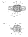
- FIG. 1 to FIG. 4 show a einrollige rope bottle for hoists with a rotatable about a rotation axis 1 deflecting device 2 for a traction means, not shown, and with a arranged below the deflection device 2 suspension 3 for a load hook 4, wherein the deflection device 2 and the suspension 3 for the load hook 4 via two in Essentially mutually parallel tie rods 5a, 5b are interconnected.
- the tie rods 5a, 5b are suspended in the illustrated embodiment in the region of the axis of rotation 1 of the deflection device 2.
- the deflection device 2 is designed as a pulley for a cable, it is of course also possible to equip the einrollige rope bottle with a sprocket for a chain as traction means.
- the suspension 3 for the rotatable about a vertical axis 6 hook 4 from a bearing holder 7, designed as an axial ball bearing thrust bearing 8 and a pressure ring 9, which are each arranged in a ring around a shaft 10 of the load hook 4.
- the undercut is formed at the free end of the shaft 10 for receiving the securing element 11 as a circumferential annular groove 10 a
- the undercut for receiving the securing element 11 as a taper of the shank cross-section, whereby lower notch stresses than in the Ring groove 10a occur.
- a receiving space 12 for fully receiving the entire suspension 3 for the load hook 4 is formed.
- tie rod body 5 is vertically aligned with its longitudinal extent in the operation of the lower bottle.
- Each of the two longitudinal halves of the tie rod body 5 forming tie rods 5a, 5b are each formed schalenfömig, so that these when assembling the blind hole-shaped and above-described receiving space 12 at the lower end of the tie rod body 5 and in the middle of a transversely to the longitudinal extent of the tie rod body 5 directed through hole 14th limit.
- This passage opening 14 serves to pass the annular deflection device 2 through the tie rod body 5.
- this tie rod body 5 is that in the upper region of the adjoining inner sides of the tie rods 5a, 5b each an achsstummelartiger approach 18a, 18b arranged. These two lugs 18a, 18b complement each other in the bolted together state of the tie rods 5a, 5b to an axis 18 with the rotation axis 1 for the rotatable mounting of the deflection 2.
- the axis 18 thus forms the bearing receptacle for the inner bearing shell of a bearing 17 of the rotatable deflection device 2, whereby the total number of components to be mounted can be further reduced.
- the two lugs 18a, 18b also limit the passage opening 14 upwards.
- FIG. 2 shows FIG. 2 in that the lugs 18a, 18b have a through hole 19a, 19b centrally in the direction of the axis of rotation 1.
- These mutually aligned through holes 19a, 19b serve to receive a first screw 15, to connect the two tie rods 5a, 5b with each other.
- the two further screw connections 16 are shown in the region of the receiving space 12.
- tie rods 5a, 5b are retracted in the region of the lugs 18a, 18b on its outer side, so that after screwed connection 15 of the screw head and the nut are recessed with respect to the outer surface of the tie rods 5a, 5b.
- the screw 15 is then covered to the outside with a cover 20 which lies in a plane with the outside of the tie rods 5a, 5b.
- the tie rods 5a, 5b are formed as metal castings.
- the undercuts 13 by the deformed free ends 5c of the tie rods 5 it is also possible to form on the mutually facing inner sides of the tie rods 5 projections on which the suspension 3 rests.
- Such trained einrollige rope bottles for hoists are characterized by their compact and simple design with low height.
Landscapes
- Engineering & Computer Science (AREA)
- Mechanical Engineering (AREA)
- Load-Engaging Elements For Cranes (AREA)
- Emergency Lowering Means (AREA)
- Cage And Drive Apparatuses For Elevators (AREA)
- Suspension Of Electric Lines Or Cables (AREA)
- Massaging Devices (AREA)
- Earth Drilling (AREA)
Abstract
Description
Die Erfindung betrifft eine einrollige Unterflasche für Hebezeuge mit einer um eine Drehachse drehbaren Umlenkvorrichtung für ein Zugmittel und einer Aufhängung für einen Lasthaken, wobei die Umlenkvorrichtung und die Aufhängung für den Lasthaken über zwei im Wesentlichen parallel zueinander angeordnete Zuganker miteinander verbunden sind.The invention relates to a einrollige lower bottle for hoists with a rotatable about a rotation deflection device for a traction device and a suspension for a load hook, wherein the deflection and the suspension for the load hook are connected to each other via two substantially mutually parallel tie rods.
Einrollige Unterflaschen für Hebezeuge mit Aufhängungen für Lasthaken sind aus der Praxis in den verschiedensten Ausführungsformen bekannt. Aus der DIN 15 411 ist eine einrollige Unterflasche bekannt, bei der der Lasthaken um eine vertikale Achse drehbar an einer Lasthaken-Aufhängung gelagert ist. Die Lasthaken-Aufhängung ist über zwei parallele Zuganker an einer Achse befestigt, auf der die Seilrolle für das Zugmittel gelagert ist. Die eigentliche Lasthaken-Aufhängung besteht bei dieser Ausführungsform aus einem die beiden Zuganker miteinander verbindenden Achsbolzen und einer auf das freie Ende des den Achsbolzen durchragenden Lasthakenschaft aufgeschraubten Mutter. Diese bekannte Bauweise weist relativ viele Bauteile auf.Single-roller bottom bottles for hoists with suspensions for load hooks are known in practice in various embodiments. From DIN 15 411 a einrollige lower bottle is known in which the load hook is mounted rotatably about a vertical axis on a load hook suspension. The load hook suspension is attached via two parallel tie rods on an axle on which the pulley is mounted for the traction means. The actual load hook suspension consists in this embodiment of a two tie rods interconnecting axle and a screwed onto the free end of the axle bolt projecting load hook shaft nut. This known construction has relatively many components.
Aus der
Aus der
Auch die
Auch aus der
Die
Davon ausgehend liegt der Erfindung die Aufgabe zugrunde, eine einfach aufgebaute einrollige Unterflasche für Hebezeuge zu schaffen.Based on this, the present invention seeks to provide a simple structure einrollige lower bottle for lifting equipment.
Diese Aufgabenstellung wird durch eine einrollige Seilflasche mit den Merkmalen des Anspruches 1 gelöst. Vorteilhafte Ausgestaltungen der Erfindung sind in den Unteransprüchen 2 bis 7 angegeben.This problem is solved by a einrollige rope bottle with the features of
Somit wird bei einer einrolligen Seilflasche für Hebezeuge mit einer um eine Drehachse drehbaren Umlenkvorrichtung für ein Zugmittel und einer Aufhängung für einen Lasthaken, wobei die Umlenkvorrichtung und die Aufhängung für den Lasthaken über zwei im Wesentlichen parallel zueinander angeordnete Zuganker miteinander verbunden sind, eine einfache Bauweise dadurch erreicht, dass mindestens einer der Zuganker eine Achse für die Umlenkvorrichtung bildet. Die Achse ist somit in mindestens einem der Zuganker integriert. Hierdurch kann erstmalig auf die Verwendung einer Achse als gesondertes Bauteil für die Lagerung der Umlenkvorrichtung verzichtet werden. Konstruktion und Montage der Unterflasche werden entsprechend einfacher.Thus, in a single-roller rope bottle for hoists with a rotatable about a rotation deflecting device for a traction device and a suspension for a load hook, wherein the deflection device and the suspension for the load hook are connected to each other via two substantially mutually parallel tie rods, a simple construction thereby achieved that at least one of the tie rods forms an axis for the deflection device. The axle is thus integrated in at least one of the tie rods. As a result, for the first time to dispense with the use of an axle as a separate component for the storage of the deflection. Design and installation of the lower bottle are correspondingly easier.
Es ist vorgesehen, dass die beiden Zuganker über Schraubverbindungen zu einem längs geteilten Zugankerkörper verbunden sind. An den aneinander zugewandten Seiten der Zuganker ist jeweils ein achstummelförmiger Ansatz angeordnet. Die Ansätze ergänzen sich dann vorteilhafter Weise im zusammen geschraubten Zustand der Zuganker zu einer Achse für die Umlenkvorrichtung.It is envisaged that the two tie rods are connected by screw to a longitudinally divided tie rod body. At the mutually facing sides of the tie rods each an Achstummelförmiger approach is arranged. The approaches complement each other then advantageously in the screwed together state of the tie rods to an axis for the deflection device.
Zur Erhöhung der Stabilität der Seilflasche liegen die Ansätze der beiden Zuganker im zusammen geschraubten Zustand der Zuganker mit ihren jeweiligen Endflächen aneinander an.To increase the stability of the rope bottle the approaches of the two tie rods are in the screwed together state of the tie rods with their respective end faces to each other.
Die Verbindung der Zuganker zu dem Zugankerkörper erfolgt einfach dadurch, dass zentral in den Ansätzen jeweils eine sich in deren Längsrichtung erstreckende Durchgangsbohrung angeordnet ist, in die eine Schraubverbindung eingesteckt ist.The connection of the tie rods to the tie rod body is carried out simply by centrally in the lugs each one extending in the longitudinal direction through hole is arranged, in which a screw is inserted.
Eine weitere Reduzierung der Bauteile wird dadurch erreicht, dass die beiden Zuganker in Bezug auf ihre Verbindungsebene im zusammen geschraubten Zustand spiegelsymmetrisch sind.A further reduction of the components is achieved in that the two tie rods are mirror-symmetrical with respect to their connection plane in the screwed-together state.
Gemäß einer Ausführungsform der Erfindung wird vorgeschlagen, dass zwischen den beiden Zugankern ein Aufnahmeraum für die vollständige Aufnahme der Aufhängung für den Lasthaken ausgebildet ist und die beiden Zuganker die in dem Aufnahmeraum gelagerte Aufhängung des Lasthakens zumindest teilweise umgreifen. Auch wird vorgeschlagen, dass die beiden Zuganker die in dem Aufnahmeraum gelagerte Aufhängung des Lasthakens zumindest teilweise umgreifen. Gemäß einer praktischen Ausführungsform der Erfindung ist vorgesehen, dass die freien Enden der beiden Zuganker zur Ausbildung des Aufnahmeraums Hinterschneidungen bildend aufeinander zu weisend ausgerichtet sind. Die aufeinander zu weisenden freien Enden der Zuganker verschließen dabei den Zwischenraum zwischen den Zugankern fast und bilden so Auflageflächen für die Lasthakenaufhängung.According to one embodiment of the invention it is proposed that between the two tie rods a receiving space for the complete recording of the suspension for the load hook is formed and the two tie rods at least partially surround the mounted in the receiving space suspension of the load hook. It is also proposed that the two tie rods at least partially surround the suspension of the load hook mounted in the receiving space. According to a practical embodiment of the invention it is provided that the free ends of the two tie rods are aligned to form the receiving space undercuts forming facing each other. The mutually facing free ends of the tie rods close the gap between the tie rods almost and thus form bearing surfaces for the hook hook suspension.
In bevorzugter Ausgestaltung sind die Zuganker als Metallgussteile ausgebildet. Somit können in einfacher Weise die Ansätze für die Bildung der Achse, der Aufnahmeraum für die Aufhängung und die Durchgangsöffnung für die Umlenkvorrichtung ausgebildet werden.In a preferred embodiment, the tie rods are formed as metal castings. Thus, the approaches for the formation of the axle, the receiving space for the suspension and the passage opening for the deflection can be easily formed.
Weitere Merkmale und Vorteile der Erfindung ergeben sich aus der zugehörigen Zeichnung, in der ein Ausführungsbeispiel einer erfindungsgemäßen einrolligen Seilflasche für Hebezeuge dargestellt ist. In der Zeichnung zeigt:
Figur 1- eine Seitenansicht einer erfindungsgemäßen einrolligen Unterflasche;
Figur 2- einen Schnitt entlang der Linie II-II gemäß
Figur 1 Figur 3- einen Schnitt entlang der Linie III-III gemäß
Figur 1 Figur 4- einen Schnitt entlang der Linie IV-IV gemäß
Figur 1
- FIG. 1
- a side view of a einrolligen lower bottle according to the invention;
- FIG. 2
- a section along the line II-II according to
FIG. 1 ; - FIG. 3
- a section along the line III-III according to
FIG. 1 and - FIG. 4
- a section along the line IV-IV according to
FIG. 1 ,
Die Abbildungen
Obwohl bei der dargestellten Ausführungsform die Umlenkvorrichtung 2 als Seilrolle für einen Seilzug ausgebildet ist, ist es selbstverständlich auch möglich, die einrollige Seilflasche mit einem Kettenrad für eine Kette als Zugmittel auszustatten.Although in the illustrated embodiment, the
Wie aus der
Das Festlegen der Aufhängung 3 am Schaft 10 des Lasthakens 4 erfolgt über ein Sicherungselement 11, wie beispielsweise einen Sprengring, das im montierten Zustand einerseits in eine als Ringnut 10a ausgebildete Hinterschneidung am freien Ende des Schaftes 10 eingreift und andererseits in einer Vertiefung 9a des Druckrings 9 angeordnet ist. Diese Bauweise hat den Vorteil, dass sie eine besonders geringe Bauhöhe der Lageranordnung 6 ermöglicht, da das freie Ende des Schaftes 10 nur geringfügig über die Oberkante des Druckrings 9 hinausragt.The fixing of the
Während in der dargestellten Ausführungsform die Hinterschneidung am freien Ende des Schaftes 10 zur Aufnahme des Sicherungselements 11 als umlaufende Ringnut 10a ausgebildet ist, ist es beispielsweise auch möglich, die Hinterschneidung zur Aufnahme des Sicherungselements 11 als Verjüngung des Schaftquerschnitts auszubilden, wodurch geringere Kerbspannungen als bei der Ringnut 10a auftreten.While in the illustrated embodiment, the undercut is formed at the free end of the
Wie weiterhin aus der
In Bezug auf die beiden Zuganker 5a, 5b ist den
Eine weitere Besonderheit dieses Zugankerkörpers 5 ist, dass in dessen oberen Bereich an den aneinander angrenzenden Innenseiten der Zuganker 5a, 5b jeweils ein achsstummelartiger Ansatz 18a, 18b angeordnet. Diese beiden Ansätze 18a, 18b ergänzen sich im miteinander verschraubten Zustand der Zuganker 5a, 5b zu einer Achse 18 mit der Drehachse 1 für die drehbare Lagerung des Umlenkmittels 2. Die Achse 18 bildet somit die Lageraufnahme für die innere Lagerschale eines Lagers 17 der drehbaren Umlenkvorrichtung 2, wodurch die Gesamtzahl der zu montierenden Bauteile weiter reduziert werden kann. Die beiden Ansätze 18a, 18b begrenzen auch die Durchgangsöffnung 14 nach oben hin.Another special feature of this
Des Weiteren zeigt die
Außerdem sind die Zuganker 5a, 5b im Bereich der Ansätze 18a, 18b an ihrer Außenseite eingezogen, so dass nach montierter Schraubverbindung 15 der Schraubkopf und die Mutter in Bezug auf die Außenoberfläche der Zuganker 5a, 5b versenkt sind. Die Schraubverbindung 15 wird dann nach außen mit einem Deckel 20 abgedeckt, der in einer Ebene mit der Außenseite der Zuganker 5a, 5b liegt. Auch sind die Zuganker 5a, 5b als Metallgussteile ausgebildet.In addition, the tie rods 5a, 5b are retracted in the region of the lugs 18a, 18b on its outer side, so that after screwed
Im zusammen geschraubten Zustand der Zuganker 5a, 5b liegen diese im Bereich des Ansätze 18a, 18b und im Bereich von Stegen 21a, 21b an den jeweiligen planen Endflächen der Ansätze 18a, 18b und der Stege 21 a, 21 b aneinander an. Die Stege 21 a, 21 b begrenzen den Aufnahmeraum 12 nach oben und trennen somit auch den Aufnahmeraum 12 von der darüber liegenden Durchgangsöffnung 14.In the screwed together state of the tie rods 5a, 5b they are in the region of the lugs 18a, 18b and in the region of
Auf Grund der vorbeschriebenen Ausbildung des Zugankerkörpers 5 ist es erstmalig möglich, auf den aus dem Stand der Technik bekannten Achsbolzen für die Umlenkvorrichtung 2 zu verzichten, die nun an den der beiden Zuganker 5a, 5b gelagert ist. Die Ansätze 18a, 18b sind jeweils Bestandteile der Zuganker 5a, 5b. Hierdurch wird ein einfacher Aufbau der Seilflasche erzielt.Due to the above-described design of the
Um die Aufhängung 3 für den Lasthaken 4 abstützend in dem Aufnahmeraum 12 zu lagern, sind bei der in
Solchermaßen ausgebildete einrollige Seilflaschen für Hebezeuge zeichnen sich durch ihre kompakte und einfache Bauweise bei gleichzeitig geringer Bauhöhe aus.Such trained einrollige rope bottles for hoists are characterized by their compact and simple design with low height.
- 11
- Drehachseaxis of rotation
- 22
- Umlenkvorrichtung/SeilrolleDeflection / pulley
- 33
- Aufhängungsuspension
- 44
- Lasthakenload hook
- 55
- ZugankerkörperZugankerkörper
- 5a5a
- Zugankertie rods
- 5b5b
- Zugankertie rods
- 5c5c
- freies Endefree end
- 66
- Achseaxis
- 77
- Lageraufnahmebearing seat
- 88th
- Axiallagerthrust
- 99
- Druckringpressure ring
- 9a9a
- Vertiefungdeepening
- 1010
- Schaftshaft
- 10a10a
- Ringnutring groove
- 1111
- Sicherungselementfuse element
- 1212
- Aufnahmeraumaccommodation space
- 1313
- Hinterschneidungundercut
- 1414
- DurchgangsöffnungThrough opening
- 1515
- Schraubverbindungscrew
- 1616
- Schraubverbindungscrew
- 1717
- Lagercamp
- 1818
- Achseaxis
- 18a18a
- Ansatzapproach
- 18b18b
- Ansatzapproach
- 19a19a
- DurchgangsbohrungThrough Hole
- 19b19b
- DurchgangsbohrungThrough Hole
- 2020
- Deckelcover
- 21a21a
- Stegweb
- 21 b21 b
- Stegweb
Claims (7)
- Single-pulley pulley block having a direction-changing device (2) rotatable about an axis of rotation (1), having a traction means, and having a suspension arrangement (3) and a connecting element, the direction-changing device (2) being fastened to the suspension arrangement (3) by means of two tie-blocks (5a, 5b) arranged substantially parallel to one another, at least one of the tie-blocks (5a, 5b) forming a shaft (18) for the direction-changing device (2), a projection (18a, 18b) in the form of a stub-shaft being arranged on each of the mutually adjacent sides of the tie-blocks (5a, 5b), and the projections (18a, 18b) complementing one another when the tie-blocks (5a, 5b) are in the connected-together state to form a shaft (18) for the direction-changing device (2) and being aligned with one another through the bearing (17), characterised in that the pulley block is the lower block of a hoist, the connecting element is a lifting hook (4) which is suspended in the suspension arrangement (3), and there is arranged centrally in each of the projections (18a, 18b) a through-hole (19a, 19b) which extends in the longitudinal direction of the projections (18a, 18b) and into which a screwed connecting means (15) is inserted to connect the tie-blocks (5a, 5b) to form the tie-block body (5).
- Pulley block according to claim 1, characterised in that the two tie-blocks (5a, 5b) are connected by screwed connecting means (15, 16) to form a longitudinally divided tie-block body (5).
- Pulley block according to claim 2, characterised in that the projections (18a, 18b) on the two tie-blocks (5a, 5b) rest against one another by their respective end-faces when the tie-blocks (5a, 5b) are in the screwed-together state.
- Pulley block according to one of claims 1 to 3, characterised in that in the screwed-together state the two tie-blocks (5a, 5b) are mirror images of one another about the plane in which they are connected.
- Pulley block according to one of claims 1 to 4, characterised in that there is formed between the two tie-blocks (5a, 5b) a receiving space (12) to receive the complete suspension arrangement (3) for the lifting hook (4), and when the suspension arrangement (3) for the lifting hook (4) is mounted in the receiving space (12) the two tie-blocks (5) fit at least partly round it.
- Pulley block according to claim 5, characterised in that the free ends (5a) of the two tie-blocks (5) are aligned to face towards one another, while forming undercuts (13), to produce the receiving space (12).
- Pulley block according to at least one of claims 1 to 6, characterised in that the tie-blocks (5a, 5b) are metal castings.
Applications Claiming Priority (2)
| Application Number | Priority Date | Filing Date | Title |
|---|---|---|---|
| DE10359876A DE10359876B4 (en) | 2003-12-18 | 2003-12-18 | Single roll lower hoist for hoists |
| DE10359876 | 2003-12-18 |
Publications (3)
| Publication Number | Publication Date |
|---|---|
| EP1544153A2 EP1544153A2 (en) | 2005-06-22 |
| EP1544153A3 EP1544153A3 (en) | 2006-06-07 |
| EP1544153B1 true EP1544153B1 (en) | 2008-02-20 |
Family
ID=34485519
Family Applications (1)
| Application Number | Title | Priority Date | Filing Date |
|---|---|---|---|
| EP04029020A Expired - Lifetime EP1544153B1 (en) | 2003-12-18 | 2004-12-08 | Lower pulley block for hoists with a single pulley |
Country Status (6)
| Country | Link |
|---|---|
| US (1) | US20050218388A1 (en) |
| EP (1) | EP1544153B1 (en) |
| CN (1) | CN1629064B (en) |
| AT (1) | ATE386702T1 (en) |
| DE (2) | DE10359876B4 (en) |
| ES (1) | ES2301921T3 (en) |
Families Citing this family (6)
| Publication number | Priority date | Publication date | Assignee | Title |
|---|---|---|---|---|
| CN101898719B (en) * | 2009-05-27 | 2012-10-10 | 无锡港盛港口机械有限公司 | Epsilon-type lifting hook device for crane |
| CN101898718B (en) * | 2009-05-27 | 2012-10-10 | 无锡港盛港口机械有限公司 | Sheep eye hook device of crane |
| DE202011001845U1 (en) | 2011-01-24 | 2012-04-30 | Liebherr-Components Biberach Gmbh | Cable drum and pulley for fiber rope drives |
| CN105197772B (en) * | 2014-12-23 | 2017-05-03 | 徐州重型机械有限公司 | Lifting hook and crane |
| CN105174037A (en) * | 2015-10-21 | 2015-12-23 | 无锡港盛重型装备有限公司 | Lifting hook mechanism for crane |
| GB2581984B (en) * | 2019-03-06 | 2022-04-27 | Treemagineers Ltd | System and apparatus for moving objects |
Family Cites Families (14)
| Publication number | Priority date | Publication date | Assignee | Title |
|---|---|---|---|---|
| US691492A (en) * | 1901-10-04 | 1902-01-21 | James Byron Roney | Pulley-block. |
| GB244180A (en) * | 1924-09-13 | 1925-12-14 | Edward Elias Von Tell | Improvements in self-locking leading blocks, and the like |
| US2206442A (en) * | 1939-01-18 | 1940-07-02 | George J Armstrong | Snatch block |
| US2332389A (en) * | 1942-03-17 | 1943-10-19 | Columbus Mckinnon Chain Corp | Hook block |
| GB573352A (en) * | 1943-12-07 | 1945-11-16 | Norman Cansfield | Improvements relating to pulley blocks |
| US2649282A (en) * | 1949-04-02 | 1953-08-18 | Jr Jessee E Fate | Snatch block |
| DE1093067B (en) * | 1958-03-12 | 1960-11-17 | Winden Und Maschb Josef Gressb | Two-part roller housing with a load hook rotatably mounted on it |
| US3378233A (en) * | 1965-07-19 | 1968-04-16 | George F Mcmurray | Roller assembly |
| US3528645A (en) * | 1968-04-18 | 1970-09-15 | Peter O Harken | Bearing block |
| US4390163A (en) * | 1981-08-28 | 1983-06-28 | Schaefer Marine, Inc. | Marine block |
| US4614332A (en) * | 1985-01-22 | 1986-09-30 | The Crosby Group, Inc. | Snatch block with improved hook bolt assembly |
| WO1995010719A1 (en) * | 1993-10-07 | 1995-04-20 | Gert Hans Frederiksen | A rope block |
| CN2377239Y (en) * | 1999-06-07 | 2000-05-10 | 廖万来 | Improved structure of pulley |
| US6910492B1 (en) * | 2002-08-09 | 2005-06-28 | Andrew G. Stuck | ATV supported shelter |
-
2003
- 2003-12-18 DE DE10359876A patent/DE10359876B4/en not_active Expired - Fee Related
-
2004
- 2004-12-08 ES ES04029020T patent/ES2301921T3/en not_active Expired - Lifetime
- 2004-12-08 AT AT04029020T patent/ATE386702T1/en not_active IP Right Cessation
- 2004-12-08 DE DE502004006247T patent/DE502004006247D1/en not_active Expired - Lifetime
- 2004-12-08 EP EP04029020A patent/EP1544153B1/en not_active Expired - Lifetime
- 2004-12-15 US US11/012,909 patent/US20050218388A1/en not_active Abandoned
- 2004-12-17 CN CN2004101046812A patent/CN1629064B/en not_active Expired - Fee Related
Also Published As
| Publication number | Publication date |
|---|---|
| DE10359876A1 (en) | 2005-07-28 |
| ES2301921T3 (en) | 2008-07-01 |
| US20050218388A1 (en) | 2005-10-06 |
| DE10359876B4 (en) | 2006-12-07 |
| EP1544153A2 (en) | 2005-06-22 |
| ATE386702T1 (en) | 2008-03-15 |
| DE502004006247D1 (en) | 2008-04-03 |
| CN1629064B (en) | 2010-06-23 |
| CN1629064A (en) | 2005-06-22 |
| EP1544153A3 (en) | 2006-06-07 |
Similar Documents
| Publication | Publication Date | Title |
|---|---|---|
| EP2388227B1 (en) | Crane hook with a hook weight assembly | |
| EP2822888A1 (en) | Eyebolt | |
| DE10164598B4 (en) | Connecting device for connecting stop or lashing devices | |
| EP2978995B1 (en) | Ball-bearing-supported attachment point | |
| DE19602931C2 (en) | Bottom block | |
| DE3601127C2 (en) | Load suspension device with improved hook bolt | |
| EP0794413B1 (en) | Measuring device with a load measuring element | |
| DE10359876B4 (en) | Single roll lower hoist for hoists | |
| EP4299501B1 (en) | Connecting device for connecting boom segments of a boom of a tower crane | |
| EP3409577B1 (en) | Device for manoeuvring a watercraft and method for producing a manoeuvring device for watercraft | |
| DE102004008552B3 (en) | Running wheel block for crane has bearing seat surfaces enclosing bearing for more than half circumference | |
| EP1963653B1 (en) | Multipart piston for an internal combustion engine | |
| DE19728779A1 (en) | Combined connection for horizontally split housings | |
| DE102004029581B4 (en) | Central joint for a wishbone of motor vehicles | |
| DE8804884U1 (en) | Soundproofing element | |
| WO2019091636A1 (en) | Level control system for adjusting the level of a vehicle, in particular a rail vehicle | |
| EP1454870A2 (en) | Suspension means for a lifting hook | |
| DE102005023990B4 (en) | Suspension of a load hook | |
| DE9310593U1 (en) | Component system for the production of crane carriageways for suspended cranes | |
| WO2013107701A1 (en) | Cable end connection and cable socket for a cable end connection | |
| EP3707050B1 (en) | Level control system for adjusting the level of a vehicle, in particular a rail vehicle | |
| DE102020131617B4 (en) | Mobile crane comprising an upper carriage with at least one bearing point for bolting on a boom | |
| DE3146829C2 (en) | Inside access device for large containers | |
| DE20121121U1 (en) | Connection device for connecting sling or lashing equipment | |
| DE10132551C2 (en) | winch |
Legal Events
| Date | Code | Title | Description |
|---|---|---|---|
| PUAI | Public reference made under article 153(3) epc to a published international application that has entered the european phase |
Free format text: ORIGINAL CODE: 0009012 |
|
| AK | Designated contracting states |
Kind code of ref document: A2 Designated state(s): AT BE BG CH CY CZ DE DK EE ES FI FR GB GR HU IE IS IT LI LT LU MC NL PL PT RO SE SI SK TR |
|
| AX | Request for extension of the european patent |
Extension state: AL BA HR LV MK YU |
|
| PUAL | Search report despatched |
Free format text: ORIGINAL CODE: 0009013 |
|
| AK | Designated contracting states |
Kind code of ref document: A3 Designated state(s): AT BE BG CH CY CZ DE DK EE ES FI FR GB GR HU IE IS IT LI LT LU MC NL PL PT RO SE SI SK TR |
|
| AX | Request for extension of the european patent |
Extension state: AL BA HR LV MK YU |
|
| 17P | Request for examination filed |
Effective date: 20060929 |
|
| 17Q | First examination report despatched |
Effective date: 20061218 |
|
| AKX | Designation fees paid |
Designated state(s): AT BE BG CH CY CZ DE DK EE ES FI FR GB GR HU IE IS IT LI LT LU MC NL PL PT RO SE SI SK TR |
|
| GRAP | Despatch of communication of intention to grant a patent |
Free format text: ORIGINAL CODE: EPIDOSNIGR1 |
|
| GRAS | Grant fee paid |
Free format text: ORIGINAL CODE: EPIDOSNIGR3 |
|
| GRAA | (expected) grant |
Free format text: ORIGINAL CODE: 0009210 |
|
| AK | Designated contracting states |
Kind code of ref document: B1 Designated state(s): AT BE BG CH CY CZ DE DK EE ES FI FR GB GR HU IE IS IT LI LT LU MC NL PL PT RO SE SI SK TR |
|
| REG | Reference to a national code |
Ref country code: GB Ref legal event code: FG4D Free format text: NOT ENGLISH |
|
| REG | Reference to a national code |
Ref country code: CH Ref legal event code: EP |
|
| REG | Reference to a national code |
Ref country code: IE Ref legal event code: FG4D Free format text: LANGUAGE OF EP DOCUMENT: GERMAN |
|
| REF | Corresponds to: |
Ref document number: 502004006247 Country of ref document: DE Date of ref document: 20080403 Kind code of ref document: P |
|
| REG | Reference to a national code |
Ref country code: ES Ref legal event code: FG2A Ref document number: 2301921 Country of ref document: ES Kind code of ref document: T3 |
|
| PG25 | Lapsed in a contracting state [announced via postgrant information from national office to epo] |
Ref country code: IS Free format text: LAPSE BECAUSE OF FAILURE TO SUBMIT A TRANSLATION OF THE DESCRIPTION OR TO PAY THE FEE WITHIN THE PRESCRIBED TIME-LIMIT Effective date: 20080620 Ref country code: FI Free format text: LAPSE BECAUSE OF FAILURE TO SUBMIT A TRANSLATION OF THE DESCRIPTION OR TO PAY THE FEE WITHIN THE PRESCRIBED TIME-LIMIT Effective date: 20080220 |
|
| NLV1 | Nl: lapsed or annulled due to failure to fulfill the requirements of art. 29p and 29m of the patents act | ||
| PG25 | Lapsed in a contracting state [announced via postgrant information from national office to epo] |
Ref country code: SI Free format text: LAPSE BECAUSE OF FAILURE TO SUBMIT A TRANSLATION OF THE DESCRIPTION OR TO PAY THE FEE WITHIN THE PRESCRIBED TIME-LIMIT Effective date: 20080220 Ref country code: PL Free format text: LAPSE BECAUSE OF FAILURE TO SUBMIT A TRANSLATION OF THE DESCRIPTION OR TO PAY THE FEE WITHIN THE PRESCRIBED TIME-LIMIT Effective date: 20080220 |
|
| REG | Reference to a national code |
Ref country code: IE Ref legal event code: FD4D |
|
| PG25 | Lapsed in a contracting state [announced via postgrant information from national office to epo] |
Ref country code: NL Free format text: LAPSE BECAUSE OF FAILURE TO SUBMIT A TRANSLATION OF THE DESCRIPTION OR TO PAY THE FEE WITHIN THE PRESCRIBED TIME-LIMIT Effective date: 20080220 Ref country code: PT Free format text: LAPSE BECAUSE OF FAILURE TO SUBMIT A TRANSLATION OF THE DESCRIPTION OR TO PAY THE FEE WITHIN THE PRESCRIBED TIME-LIMIT Effective date: 20080721 Ref country code: SE Free format text: LAPSE BECAUSE OF FAILURE TO SUBMIT A TRANSLATION OF THE DESCRIPTION OR TO PAY THE FEE WITHIN THE PRESCRIBED TIME-LIMIT Effective date: 20080520 Ref country code: CZ Free format text: LAPSE BECAUSE OF FAILURE TO SUBMIT A TRANSLATION OF THE DESCRIPTION OR TO PAY THE FEE WITHIN THE PRESCRIBED TIME-LIMIT Effective date: 20080220 Ref country code: SK Free format text: LAPSE BECAUSE OF FAILURE TO SUBMIT A TRANSLATION OF THE DESCRIPTION OR TO PAY THE FEE WITHIN THE PRESCRIBED TIME-LIMIT Effective date: 20080220 Ref country code: DK Free format text: LAPSE BECAUSE OF FAILURE TO SUBMIT A TRANSLATION OF THE DESCRIPTION OR TO PAY THE FEE WITHIN THE PRESCRIBED TIME-LIMIT Effective date: 20080220 Ref country code: IE Free format text: LAPSE BECAUSE OF FAILURE TO SUBMIT A TRANSLATION OF THE DESCRIPTION OR TO PAY THE FEE WITHIN THE PRESCRIBED TIME-LIMIT Effective date: 20080220 |
|
| PG25 | Lapsed in a contracting state [announced via postgrant information from national office to epo] |
Ref country code: RO Free format text: LAPSE BECAUSE OF FAILURE TO SUBMIT A TRANSLATION OF THE DESCRIPTION OR TO PAY THE FEE WITHIN THE PRESCRIBED TIME-LIMIT Effective date: 20080220 |
|
| PLBE | No opposition filed within time limit |
Free format text: ORIGINAL CODE: 0009261 |
|
| STAA | Information on the status of an ep patent application or granted ep patent |
Free format text: STATUS: NO OPPOSITION FILED WITHIN TIME LIMIT |
|
| 26N | No opposition filed |
Effective date: 20081121 |
|
| PG25 | Lapsed in a contracting state [announced via postgrant information from national office to epo] |
Ref country code: LT Free format text: LAPSE BECAUSE OF FAILURE TO SUBMIT A TRANSLATION OF THE DESCRIPTION OR TO PAY THE FEE WITHIN THE PRESCRIBED TIME-LIMIT Effective date: 20080220 |
|
| PG25 | Lapsed in a contracting state [announced via postgrant information from national office to epo] |
Ref country code: BG Free format text: LAPSE BECAUSE OF FAILURE TO SUBMIT A TRANSLATION OF THE DESCRIPTION OR TO PAY THE FEE WITHIN THE PRESCRIBED TIME-LIMIT Effective date: 20080520 Ref country code: EE Free format text: LAPSE BECAUSE OF FAILURE TO SUBMIT A TRANSLATION OF THE DESCRIPTION OR TO PAY THE FEE WITHIN THE PRESCRIBED TIME-LIMIT Effective date: 20080220 |
|
| BERE | Be: lapsed |
Owner name: DEMAG CRANES & COMPONENTS G.M.B.H. Effective date: 20081231 |
|
| PG25 | Lapsed in a contracting state [announced via postgrant information from national office to epo] |
Ref country code: MC Free format text: LAPSE BECAUSE OF NON-PAYMENT OF DUE FEES Effective date: 20081231 Ref country code: CY Free format text: LAPSE BECAUSE OF FAILURE TO SUBMIT A TRANSLATION OF THE DESCRIPTION OR TO PAY THE FEE WITHIN THE PRESCRIBED TIME-LIMIT Effective date: 20080220 |
|
| REG | Reference to a national code |
Ref country code: CH Ref legal event code: PL |
|
| PG25 | Lapsed in a contracting state [announced via postgrant information from national office to epo] |
Ref country code: BE Free format text: LAPSE BECAUSE OF NON-PAYMENT OF DUE FEES Effective date: 20081231 |
|
| PG25 | Lapsed in a contracting state [announced via postgrant information from national office to epo] |
Ref country code: CH Free format text: LAPSE BECAUSE OF NON-PAYMENT OF DUE FEES Effective date: 20081231 Ref country code: LI Free format text: LAPSE BECAUSE OF NON-PAYMENT OF DUE FEES Effective date: 20081231 |
|
| PG25 | Lapsed in a contracting state [announced via postgrant information from national office to epo] |
Ref country code: AT Free format text: LAPSE BECAUSE OF NON-PAYMENT OF DUE FEES Effective date: 20081208 |
|
| PG25 | Lapsed in a contracting state [announced via postgrant information from national office to epo] |
Ref country code: LU Free format text: LAPSE BECAUSE OF NON-PAYMENT OF DUE FEES Effective date: 20081208 Ref country code: HU Free format text: LAPSE BECAUSE OF FAILURE TO SUBMIT A TRANSLATION OF THE DESCRIPTION OR TO PAY THE FEE WITHIN THE PRESCRIBED TIME-LIMIT Effective date: 20080821 |
|
| PG25 | Lapsed in a contracting state [announced via postgrant information from national office to epo] |
Ref country code: TR Free format text: LAPSE BECAUSE OF FAILURE TO SUBMIT A TRANSLATION OF THE DESCRIPTION OR TO PAY THE FEE WITHIN THE PRESCRIBED TIME-LIMIT Effective date: 20080220 |
|
| PG25 | Lapsed in a contracting state [announced via postgrant information from national office to epo] |
Ref country code: GR Free format text: LAPSE BECAUSE OF FAILURE TO SUBMIT A TRANSLATION OF THE DESCRIPTION OR TO PAY THE FEE WITHIN THE PRESCRIBED TIME-LIMIT Effective date: 20080521 |
|
| REG | Reference to a national code |
Ref country code: FR Ref legal event code: PLFP Year of fee payment: 12 |
|
| REG | Reference to a national code |
Ref country code: DE Ref legal event code: R081 Ref document number: 502004006247 Country of ref document: DE Owner name: TEREX MHPS GMBH, DE Free format text: FORMER OWNER: DEMAG CRANES COMPONENTS GMBH, 58300 WETTER, DE Ref country code: DE Ref legal event code: R082 Ref document number: 502004006247 Country of ref document: DE Representative=s name: MOSER GOETZE & PARTNER PATENTANWAELTE MBB, DE Ref country code: DE Ref legal event code: R081 Ref document number: 502004006247 Country of ref document: DE Owner name: TEREX MHPS GMBH, DE Free format text: FORMER OWNER: DEMAG CRANES & COMPONENTS GMBH, 58300 WETTER, DE |
|
| REG | Reference to a national code |
Ref country code: FR Ref legal event code: PLFP Year of fee payment: 13 |
|
| PGFP | Annual fee paid to national office [announced via postgrant information from national office to epo] |
Ref country code: GB Payment date: 20161222 Year of fee payment: 13 Ref country code: DE Payment date: 20161213 Year of fee payment: 13 |
|
| PGFP | Annual fee paid to national office [announced via postgrant information from national office to epo] |
Ref country code: FR Payment date: 20161222 Year of fee payment: 13 Ref country code: ES Payment date: 20161213 Year of fee payment: 13 |
|
| PGFP | Annual fee paid to national office [announced via postgrant information from national office to epo] |
Ref country code: IT Payment date: 20161223 Year of fee payment: 13 |
|
| REG | Reference to a national code |
Ref country code: DE Ref legal event code: R119 Ref document number: 502004006247 Country of ref document: DE |
|
| GBPC | Gb: european patent ceased through non-payment of renewal fee |
Effective date: 20171208 |
|
| REG | Reference to a national code |
Ref country code: FR Ref legal event code: ST Effective date: 20180831 |
|
| PG25 | Lapsed in a contracting state [announced via postgrant information from national office to epo] |
Ref country code: IT Free format text: LAPSE BECAUSE OF NON-PAYMENT OF DUE FEES Effective date: 20171208 Ref country code: FR Free format text: LAPSE BECAUSE OF NON-PAYMENT OF DUE FEES Effective date: 20180102 Ref country code: DE Free format text: LAPSE BECAUSE OF NON-PAYMENT OF DUE FEES Effective date: 20180703 |
|
| PG25 | Lapsed in a contracting state [announced via postgrant information from national office to epo] |
Ref country code: GB Free format text: LAPSE BECAUSE OF NON-PAYMENT OF DUE FEES Effective date: 20171208 |
|
| REG | Reference to a national code |
Ref country code: ES Ref legal event code: FD2A Effective date: 20190702 |
|
| PG25 | Lapsed in a contracting state [announced via postgrant information from national office to epo] |
Ref country code: ES Free format text: LAPSE BECAUSE OF NON-PAYMENT OF DUE FEES Effective date: 20171209 |