EP1454870A2 - Suspension means for a lifting hook - Google Patents
Suspension means for a lifting hook Download PDFInfo
- Publication number
- EP1454870A2 EP1454870A2 EP04004899A EP04004899A EP1454870A2 EP 1454870 A2 EP1454870 A2 EP 1454870A2 EP 04004899 A EP04004899 A EP 04004899A EP 04004899 A EP04004899 A EP 04004899A EP 1454870 A2 EP1454870 A2 EP 1454870A2
- Authority
- EP
- European Patent Office
- Prior art keywords
- suspension according
- bearing
- ring
- load hook
- receiving ring
- Prior art date
- Legal status (The legal status is an assumption and is not a legal conclusion. Google has not performed a legal analysis and makes no representation as to the accuracy of the status listed.)
- Granted
Links
Images


Classifications
-
- B—PERFORMING OPERATIONS; TRANSPORTING
- B66—HOISTING; LIFTING; HAULING
- B66C—CRANES; LOAD-ENGAGING ELEMENTS OR DEVICES FOR CRANES, CAPSTANS, WINCHES, OR TACKLES
- B66C1/00—Load-engaging elements or devices attached to lifting or lowering gear of cranes or adapted for connection therewith for transmitting lifting forces to articles or groups of articles
- B66C1/10—Load-engaging elements or devices attached to lifting or lowering gear of cranes or adapted for connection therewith for transmitting lifting forces to articles or groups of articles by mechanical means
- B66C1/22—Rigid members, e.g. L-shaped members, with parts engaging the under surface of the loads; Crane hooks
- B66C1/34—Crane hooks
Definitions
- the invention relates to a suspension for load hook, in particular for Bottoms of cables, with one in a recess of a supporting body to a vertical axis rotatably mounted shaft, which, in one Through hole of a support member mounted over at least one Axial bearing supported on the support body.
- Suspensions for load hooks are from practice in the most varied Embodiments known. From DIN 15 411 is a lower bottle with two Pulleys are known in which the load hook around a vertical and a horizontal Axis is rotatably mounted on a load hook suspension, below the the Cable pulleys bearing connecting body is arranged. Due to the use on the one hand the connecting body and on the other hand the separate load hook suspension This known construction has a relatively large height and also many components on.
- a generic load hook suspension is known from German patent DE 196 02 931 C2 known.
- the shaft of the load hook is in one Recess of the pulleys bearing connecting body of a lower bottle stored.
- the inserted into the recess and the shaft of the load hook superimposed thrust bearing is tangentially extending screws in the recess held by the pulleys ago in Tangentialnuten the bearing cage be screwed.
- This tangential screwing of the thrust bearing in the recess is the mounting of this known suspension very expensive and since it is an exact positioning of the bearing cage with the stored therein Loading hook in the recess of the connecting body requires because the Tangential screws only in one position fixing into the tangential grooves of the Bearing cage can be screwed.
- the present invention seeks to provide a short-building and to create a simple suspension for a load hook.
- the shaft of the load hook on a from the support element, the at least one thrust bearing and a ring surrounding the shaft Receiving ring existing bearing assembly is mounted in the support body, wherein the bearing arrangement, preferably the receiving ring, via a securing element, in particular a snap ring, is fixed in the support body.
- the storage according to the invention allows the entire bearing arrangement to pre-assemble the insertion in the recess of the support body. About that In addition, it only needs to set the bearing assembly in the recess a fuse element, such as a snap ring. The assembly is thus easy and quick to carry out, especially since there is no special positioning requires the bearing assembly to the support body and / or the recess.
- the securing element for Securing the bearing assembly on the one hand an undercut of the support body engages behind and on the other hand rests against a contact surface of the receiving ring.
- the entire bearing assembly stored in this embodiment on the on Supporting body supporting securing element.
- the Undercut for receiving the securing element as a circumferential annular groove formed in the support body.
- the setting of the load hook shaft on the support element is carried out according to a preferred embodiment of the invention via a securing element, in particular a snap ring, the one hand in the mounted state Undercut at the free end of the shaft engages behind and on the other hand in one Deepening of the support element is arranged.
- a securing element in particular a snap ring
- the thrust bearing facing surface of the support element and / or the receiving ring as a plane contact surface for the particular as Axial needle bearing trained thrust bearing formed.
- the support element forms even the upper bearing shell of the thrust bearing, reducing the number of components can be further reduced.
- the Load hook in addition to the twistability about the vertical axis by one horizontal axis is pivotally mounted in the support body. Through this additional degree of freedom can be the handling and use significantly increase a load hook mounted according to the invention.
- This Pivotability about a horizontal axis is advantageously by two between the lower bearing shell of the thrust bearing and the receiving ring arranged cylindrical rollers achieved, which form the horizontal pivot axis, wherein the cylindrical rollers opposite each other on both sides of the shank of Load hooks are arranged in the bearing assembly.
- the number of the formation of the bearing assembly according to the invention necessary components can be further reduced that the Cylindrical rollers between the receiving ring and a lower bearing shell of the Thrust bearing forming the shaft annularly surrounding pivot bearing ring are arranged.
- the pivoting about the horizontal axis can be facilitated and also in the Verschwenkwinkel is limited, that on the one hand in a plane perpendicular to the Pivot axis between the mutually facing surfaces of the receiving ring and the pivot bearing ring is formed a gap and on the other hand the Side walls of the through hole of the receiving ring at least in the The pivoting plane of the load hook is conically widened in the direction of the load hook are formed.
- the limitation of the pivoting angle is made possible by the fact that the facing surfaces of the receiving ring and the pivot bearing ring and / or the conical side walls of the through hole of the receiving ring form the pivoting angle of the load hook limiting stop surfaces.
- the gap between the facing surfaces of the receiving ring and the pivot bearing ring is advantageously in radially outward pointing direction widening trained.
- the handling of the load hook provided device facilitating at least one recessed grip formed in the support body.
- a connecting body of a Bottom trained and provided with the at least one recessed grip Support body is easy and inexpensive to manufacture as a casting
- a with Handholds provided with forged load hook as he from the state of Technology is known, represents a complex and expensive to manufacture special component.
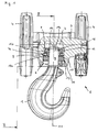
- FIG. 1 to Figure 5 show two embodiments of the Embodiment of the suspension of a load hook 1, which in a recess. 2 a supporting body 3 is mounted.
- the supporting body 3 as two pulleys 4 a lower block 5 supporting Formed connecting body.
- This fuse element 12 can, as in the figures, Figure 1 to Figure 5 represented, for example, be designed as a snap ring, the one Undercut 13, in particular an annular groove in the support body 3 engages behind.
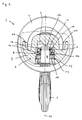
- FIG. 2 The sectional side view of Figure 2 it can be seen that the Facilitation of handling in the support body 3 recessed grips 17 are formed.
- the Training the recessed grips 17 on the support body 3 is particularly advantageous because a provided with recessed grips 17 supporting body 3 simple and inexpensive than Casting is to be finished, while a forged grips 17 forged Load hook 1, as known from the prior art, a complex and represents expensive to be manufactured special component.
- the pivot bearing ring 20 the bearing shells of the thrust bearing 8
- the Thrust bearing 8 had its own storage cage.
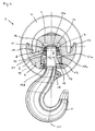
- FIGs 4 and 5 is a concrete embodiment of the Swivel bearing ring 20 and the receiving ring 10 can be seen by the The load hook 1, on the one hand, can easily be pivoted about the axis 18, on the other hand also the pivot angle can be limited.
- side walls 10b are through-holes of the receiving ring 10 at least in the pivoting plane of the load hook 1 in the direction of the load hook. 1 is formed conically widened to the pivoting of the load hook 1 to enable.
- the mutually facing contact surfaces 10a, 20a of the receiving ring 10 and the Swivel bearing ring 20 and / or the conical side walls 10b of the receiving ring 10 thus form the pivot angle of the load hook 1 limiting Stop surfaces.
- Such trained suspensions for hooks 1 are on the one hand by their compact design with low height and wise on the other the advantage that the entire bearing assembly 6 outside the support body. 3 can be pre-assembled. For the actual assembly on the support body 3 is required Finally, only the onset of the shaft 9 of the load hook. 1 preassembled bearing assembly 6 in the recess 2 in the support body 3 and the Fixing the bearing assembly 6 via the securing element 12 on the support body Third
Abstract
Description
Die Erfindung betrifft eine Aufhängung für Lasthaken, insbesondere für Unterflaschen von Seilzügen, mit einem in einer Ausnehmung eines Tragkörpers um eine vertikale Achse drehbar gelagerten Schaft, der sich, in einer Durchgangsbohrung eines Abstützelements gelagert, über mindestens ein Axiallager am Tragkörper abstützt.The invention relates to a suspension for load hook, in particular for Bottoms of cables, with one in a recess of a supporting body to a vertical axis rotatably mounted shaft, which, in one Through hole of a support member mounted over at least one Axial bearing supported on the support body.
Aufhängungen für Lasthaken sind aus der Praxis in den verschiedensten Ausführungsformen bekannt. Aus der DIN 15 411 ist eine Unterflasche mit zwei Seilrollen bekannt, bei der der Lasthaken um eine vertikale und eine horizontale Achse drehbar an einer Lasthaken-Aufhängung gelagert ist, die unterhalb des die Seilrollen tragenden Verbindungskörpers angeordnet ist. Aufgrund der Verwendung einerseits des Verbindungskörpers und andererseits der separaten Lasthaken-Aufhängung weist diese bekannte Bauweise eine relativ große Bauhöhe und zudem viele Bauteile auf.Suspensions for load hooks are from practice in the most varied Embodiments known. From DIN 15 411 is a lower bottle with two Pulleys are known in which the load hook around a vertical and a horizontal Axis is rotatably mounted on a load hook suspension, below the the Cable pulleys bearing connecting body is arranged. Due to the use on the one hand the connecting body and on the other hand the separate load hook suspension This known construction has a relatively large height and also many components on.
Eine gattungsgemäße Lasthaken-Aufhängung ist aus dem deutsche Patent DE 196 02 931 C2 bekannt. Bei dieser Aufhängung ist der Schaft des Lasthakens in einer Ausnehmung des die Seilrollen tragenden Verbindungskörpers einer Unterflasche gelagert. Das in die Ausnehmung eingesetzte und den Schaft des Lasthakens lagernde Axiallager wird über tangential verlaufende Schrauben in der Ausnehmung gehalten, die von den Seilrollen her in Tangentialnuten des Lagerkäfigs eingeschraubt werden. Durch dieses tangentiale Verschrauben des Axiallagers in der Ausnehmung ist die Montage dieser bekannten Aufhängung sehr aufwendig und da es einer exakten Positionierung des Lagerkäfigs mit dem darin gelagerten Lasthaken in der Ausnehmung des Verbindungskörpers bedarf, weil die Tangentialschrauben nur in einer Stellung fixierend in die Tangentialnuten des Lagerkäfigs einschraubbar sind.A generic load hook suspension is known from German patent DE 196 02 931 C2 known. In this suspension, the shaft of the load hook is in one Recess of the pulleys bearing connecting body of a lower bottle stored. The inserted into the recess and the shaft of the load hook superimposed thrust bearing is tangentially extending screws in the recess held by the pulleys ago in Tangentialnuten the bearing cage be screwed. By this tangential screwing of the thrust bearing in the recess is the mounting of this known suspension very expensive and since it is an exact positioning of the bearing cage with the stored therein Loading hook in the recess of the connecting body requires because the Tangential screws only in one position fixing into the tangential grooves of the Bearing cage can be screwed.
Eine weitere Aufhängung für Lasthaken ist aus der deutschen Offenlegungsschrift DE 198 17 011 A1 bekannt. Bei dieser bekannten Lasthaken-Aufhängung für eine Unterflasche ist der Lasthaken sowohl um eine vertikale als auch um eine horizontale Achse drehbar gelagert. Zu diesem Zweck umfasst die in der Ausnehmung des die Seilrollen tragenden Verbindungskörpers angeordnete Lageranordnung für den Lasthakenschaft neben dem Axiallager für die Drehung um die vertikale Achse einen zylindrischen Zapfen, der die Ausnehmung überbrückend drehbar im Verbindungskörper gelagert ist. Zur Aufnahme des Lasthakenschaftes weist der zylindrische Zapfen eine Durchgangsbohrung auf. Auf das aus der Durchgangsbohrung herausragende freie Ende des Lasthakenschaftes wird eine Mutter aufgeschraubt und so der Lasthaken an dem zylindrischen Zapfen festgelegt. Durch die Verwendung des zylindrischen Lagerzapfens weist die gesamte Lageranordnung eine relativ große Bauhöhe auf und besteht zudem aus vielen nicht vormontierbaren Bauteilen.Another suspension for hooks is from the German patent application DE 198 17 011 A1. In this known load hook suspension for a Unterflasche is the load hook both around a vertical as well as around a horizontal axis rotatably mounted. For this purpose, the includes in the Recess of the rope pulleys carrying connecting body arranged Bearing arrangement for the load hook shaft next to the thrust bearing for rotation around the vertical axis a cylindrical pin, bridging the recess is rotatably mounted in the connecting body. For receiving the load hook shaft the cylindrical pin has a through hole. On the from the Through hole outstanding free end of the load hook shaft is a Screwed nut and set the load hook on the cylindrical pin. Through the use of the cylindrical journal, the entire Bearing arrangement a relatively large height and also consists of many not pre-assembled components.
Davon ausgehend liegt der Erfindung die Aufgabe zugrunde, eine kurz bauende und einfach aufgebaute Aufhängung für einen Lasthaken zu schaffen.Based on this, the present invention seeks to provide a short-building and to create a simple suspension for a load hook.
Die Lösung dieser Aufgabenstellung ist erfindungsgemäß dadurch gekennzeichnet, dass der Schaft des Lasthakens über eine aus dem Abstützelement, dem mindestens einen Axiallager sowie einem den Schaft ringförmig umgebenden Aufnahmering bestehende Lageranordnung in dem Tragkörper gelagert ist, wobei die Lageranordnung, vorzugsweise der Aufnahmering, über ein Sicherungselement, insbesondere einen Sprengring, im Tragkörper festgelegt ist.The solution to this problem is inventively characterized that the shaft of the load hook on a from the support element, the at least one thrust bearing and a ring surrounding the shaft Receiving ring existing bearing assembly is mounted in the support body, wherein the bearing arrangement, preferably the receiving ring, via a securing element, in particular a snap ring, is fixed in the support body.
Die erfindungsgemäße Lagerung ermöglicht es, die gesamte Lageranordnung vor dem Einsetzen in die Ausnehmung des Tragkörpers vorzumontieren. Darüber hinaus bedarf es zum Festlegen der Lageranordnung in der Ausnehmung lediglich eines Sicherungselements, wie beispielsweise eines Sprengrings. Die Montage ist somit einfach und schnell durchführbar, zumal es keiner besonderen Positionierung der Lageranordnung zum Tragkörper und/oder der Ausnehmung bedarf.The storage according to the invention allows the entire bearing arrangement to pre-assemble the insertion in the recess of the support body. About that In addition, it only needs to set the bearing assembly in the recess a fuse element, such as a snap ring. The assembly is thus easy and quick to carry out, especially since there is no special positioning requires the bearing assembly to the support body and / or the recess.
Schließlich wird mit der Erfindung vorgeschlagen, dass das Sicherungselement zur Sicherung der Lageranordnung einerseits eine Hinterschneidung des Tragkörpers hintergreift und andererseits an einer Anlagefläche des Aufnahmerings anliegt. Die gesamte Lageranordnung lagert bei dieser Ausgestaltungsform auf dem sich am Tragkörper abstützenden Sicherungselement. Vorteilhafterweise ist die Hinterschneidung zur Aufnahme des Sicherungselements als umlaufende Ringnut im Tragkörper ausgebildet.Finally, it is proposed with the invention that the securing element for Securing the bearing assembly on the one hand an undercut of the support body engages behind and on the other hand rests against a contact surface of the receiving ring. The entire bearing assembly stored in this embodiment on the on Supporting body supporting securing element. Advantageously, the Undercut for receiving the securing element as a circumferential annular groove formed in the support body.
Das Festlegen des Lasthakenschaftes am Abstützelement erfolgt gemäß einer bevorzugten Ausführungsform der Erfindung über ein Sicherungselement, insbesondere einen Sprengring, das im montierten Zustand einerseits eine Hinterschneidung am freien Ende des Schaftes hintergreift und andererseits in einer Vertiefung des Abstützelements angeordnet ist.The setting of the load hook shaft on the support element is carried out according to a preferred embodiment of the invention via a securing element, in particular a snap ring, the one hand in the mounted state Undercut at the free end of the shaft engages behind and on the other hand in one Deepening of the support element is arranged.
Bei einer ersten praktischen Ausführungsform ist die die Hinterschneidung zur Aufnahme des Sicherungselements als umlaufende Ringnut im Lasthakenschaft ausgebildet ist.In a first practical embodiment, which is the undercut for Recording of the securing element as a circumferential annular groove in the load hook shaft is trained.
Zur Verringerung der auftretenden Kerbspannungen wird gemäß einer zweiten Ausführungsform vorgeschlagen, dass die Hinterschneidung zur Aufnahme des Sicherungselements als vom freien Ende des Schaftes fortweisende Verjüngung des Schaftquerschnittes ausgebildet ist.To reduce the notch stresses occurring in accordance with a second Embodiment suggested that the undercut to accommodate the Fuse element as the free end of the shaft-facing taper the shank cross-section is formed.
Vorteilhafterweise ist die dem Axiallager zugewandte Fläche des Abstützelements und/oder des Aufnahmerings als plane Anlagefläche für das insbesondere als Axialnadellager ausgebildete Axiallager ausgebildet.Advantageously, the thrust bearing facing surface of the support element and / or the receiving ring as a plane contact surface for the particular as Axial needle bearing trained thrust bearing formed.
Gemäß einer alternativen Ausführungsform der Erfindung bildet das Abstützelement selbst die obere Lagerschale des Axiallagers, wodurch die Anzahl der Bauteile weiter verringert werden kann.According to an alternative embodiment of the invention, the support element forms even the upper bearing shell of the thrust bearing, reducing the number of components can be further reduced.
Mit einer bevorzugten Weiterbildung der Erfindung wird vorgeschlagen, dass der Lasthaken zusätzlich zu der Verdrehbarkeit um die vertikale Achse um eine horizontale Achse verschwenkbar im Tragkörper gelagert ist. Durch diesen zusätzlichen Freiheitsgrad lassen sich die Handhabung und Einsatzmöglichkeit eines erfindungsgemäß gelagerten Lasthakens deutlich erhöhen. Diese Verschwenkbarkeit um eine horizontale Achse wird vorteilhafterweise durch zwei zwischen der unteren Lagerschale des Axiallagers und dem Aufnahmering angeordnete Zylinderrollen erzielt, die die horizontale Schwenkachse bilden, wobei die Zylinderrollen einander gegenüberliegend beidseitig des Schaftes des Lasthakens in der Lageranordnung angeordnet sind.With a preferred development of the invention it is proposed that the Load hook in addition to the twistability about the vertical axis by one horizontal axis is pivotally mounted in the support body. Through this additional degree of freedom can be the handling and use significantly increase a load hook mounted according to the invention. This Pivotability about a horizontal axis is advantageously by two between the lower bearing shell of the thrust bearing and the receiving ring arranged cylindrical rollers achieved, which form the horizontal pivot axis, wherein the cylindrical rollers opposite each other on both sides of the shank of Load hooks are arranged in the bearing assembly.
Die Anzahl der zur Ausbildung der erfindungsgemäßen Lageranordnung notwendigen Bauteile kann dadurch weiter verringert werden, dass die Zylinderrollen zwischen dem Aufnahmering und einem die untere Lagerschale des Axiallagers bildenden, den Schaft ringförmig umgebenden Schwenklagerring angeordnet sind.The number of the formation of the bearing assembly according to the invention necessary components can be further reduced that the Cylindrical rollers between the receiving ring and a lower bearing shell of the Thrust bearing forming the shaft annularly surrounding pivot bearing ring are arranged.
Das Verschwenken um die horizontale Achse kann dadurch erleichtert und auch im Verschwenkwinkel begrenzt werde, dass einerseits in einer Ebene rechtwinklig zur Schwenkachse zwischen den einander zugewandten Flächen des Aufnahmerings und des Schwenklagerrings ein Spalt ausgebildet ist und andererseits die Seitenwände der Durchgangsbohrung des Aufnahmerings zumindest in der Verschwenkebene des Lasthakens in Richtung zum Lasthaken konisch erweitert ausgebildet sind.The pivoting about the horizontal axis can be facilitated and also in the Verschwenkwinkel is limited, that on the one hand in a plane perpendicular to the Pivot axis between the mutually facing surfaces of the receiving ring and the pivot bearing ring is formed a gap and on the other hand the Side walls of the through hole of the receiving ring at least in the The pivoting plane of the load hook is conically widened in the direction of the load hook are formed.
Die Begrenzung des Verschwenkwinkels wird dadurch ermöglicht, dass die einander zugewandten Flächen des Aufnahmerings und des Schwenklagerrings und/oder die konischen Seitenwände der Durchgangsbohrung des Aufnahmerings den Verschwenkwinkel des Lasthakens begrenzende Anschlagflächen bilden. Der Spalt zwischen den einander zugewandten Flächen des Aufnahmerings und des Schwenklagerring ist dabei vorteilhafterweise sich in radial nach außen weisender Richtung erweiternd ausgebildet.The limitation of the pivoting angle is made possible by the fact that the facing surfaces of the receiving ring and the pivot bearing ring and / or the conical side walls of the through hole of the receiving ring form the pivoting angle of the load hook limiting stop surfaces. The gap between the facing surfaces of the receiving ring and the pivot bearing ring is advantageously in radially outward pointing direction widening trained.
Schließlich wird mit der Erfindung vorgeschlagen, dass die Handhabung der mit dem Lasthaken versehenen Vorrichtung erleichternde mindestens eine Griffmulde im Tragkörper ausgebildet. Der beispielsweise als Verbindungskörper einer Unterflasche ausgebildete und mit der mindestens einen Griffmulde versehene Tragkörper ist einfach und kostengünstig als Gussteil zu fertigen, während ein mit Griffmulden versehener geschmiedeter Lasthaken, wie er aus dem Stand der Technik bekannt ist, ein aufwendig und teuer zu fertigendes Sonderbauteil darstellt.Finally, it is proposed with the invention that the handling of the load hook provided device facilitating at least one recessed grip formed in the support body. For example, as a connecting body of a Bottom trained and provided with the at least one recessed grip Support body is easy and inexpensive to manufacture as a casting, while a with Handholds provided with forged load hook, as he from the state of Technology is known, represents a complex and expensive to manufacture special component.
Weitere Merkmale und Vorteile der Erfindung ergeben sich anhand der zugehörigen Zeichnung, in der zwei Ausführungsbeispiele einer erfindungsgemäßen Aufhängung für Lasthaken nur beispielhaft dargestellt sind. In der Zeichnung zeigt:
Figur 1- eine teilweise geschnittene Vorderansicht einer an einer Unterflasche angeordneten Lasthaken-Aufhängung gemäß einer ersten erfindungsgemäßen Ausführungsform;
Figur 2- einen Schnitt entlang der Linie II-II gemäß
Figur 1; Figur 3- eine teilweise geschnittene Vorderansicht einer an einer Unterflasche angeordneten Lasthaken-Aufhängung gemäß einer zweiten erfindungsgemäßen Ausführungsform;
Figur 4- einen Schnitt entlang der Linie IV-IV gemäß
Figur 3 und Figur 5- eine Ansicht gemäß
Figur 4, jedoch den Lasthaken in einer verschwenkten Position darstellend.
- FIG. 1
- a partially sectioned front view of a arranged on a lower block load hook suspension according to a first embodiment of the invention;
- FIG. 2
- a section along the line II-II of Figure 1;
- FIG. 3
- a partially sectioned front view of a hook arranged on a bottom hook hook suspension according to a second embodiment of the invention;
- FIG. 4
- a section along the line IV-IV according to Figure 3 and
- FIG. 5
- a view according to Figure 4, but the load hook in a pivoted position performing.
Die Abbildungen Figur 1 bis Figur 5 zeigen zwei Ausführungsbeispiele zur
Ausgestaltung der Aufhängung eines Lasthakens 1, der in einer Ausnehmung 2
eines Tragkörpers 3 gelagert ist. Bei den dargestellten Ausführungsbeispielen ist
der Tragkörper 3 als zwei Seilrollen 4 einer Unterflasche 5 tragender
Verbindungskörper ausgebildet.The figures Figure 1 to Figure 5 show two embodiments of the
Embodiment of the suspension of a
Wie aus den Abbildungen ersichtlich, besteht eine die Aufhängung des Lasthakens
1 bildende Lageranordnung 6 zumindest aus einem ringförmigen Abstützelement 7,
einem Axiallager 8 sowie einem einen Schaft 9 des Lasthakens 1 ringförmig
umgebenden Aufnahmering 10, wobei der Lasthaken 1 durch den Einsatz des
Axiallagers 8 um eine vertikale Achse 11 drehbar gelagert ist. Die gesamte in der
Ausnehmung 2 des Tragkörpers 3 gelagerte Lageranordnung 6 wird über ein
Sicherungselement 12 in der Ausnehmung 2 des Tragkörpers 3 gehalten.As can be seen from the figures, there is a suspension of the
Dieses Sicherungselement 12 kann, wie in den Abbildungen Figur 1 bis Figur 5
dargestellt, beispielsweise als Sprengring ausgebildet sein, der eine
Hinterschneidung 13, insbesondere eine Ringnut, im Tragkörper 3 hintergreift. This
Bei der in den Abbildungen Figur 1 und 2 dargestellten ersten Ausführungsform ist
der Lasthaken 1 ausschließlich um die vertikale Achse 11 drehbar im Tragkörper 3
gelagert. Zur Lagerung des Axiallagers 8 weisen bei dieser Ausführungsform sowohl
das Abstützelement 7 als auch der Aufnahmering 10 plane Anlageflächen 7a, 10a
auf, an denen die Lagerschalen des Axiallagers anliegen.In the first embodiment shown in Figures 1 and 2 is
the
Das Festlegen des Schaftes 9 des Lasthakens 1 erfolgt über ein Sicherungselement
14, wie beispielsweise einen Sprengring, das im montierten Zustand einerseits eine
Hinterschneidung 15 am freien Ende des Schaftes 9 hintergreift und andererseits in
einer Vertiefung 16 des Abstützelements 7 angeordnet ist. Diese Bauweise hat den
Vorteil, dass sie eine besonders geringe Bauhöhe der Lageranordnung 6
ermöglicht, da das freie Ende des Schaftes 9 nur geringfügig über die Oberkante
des Abstützelements 7 hinausragt. Bei der Darstellung gemäß Figur 1 sind zwei
Ausführungsformen zur Ausgestaltung der Hinterschneidung 15 zur Aufnahme des
Sicherungselements 14 am Schaft 9 dargestellt, obwohl in der Praxis
selbstverständlicher Weise immer nur eine Ausführungsform bei einer
Lageranordnung 6 verwendet wird.The setting of the shaft 9 of the
Auf der rechten Hälfte des Schaftes 9 ist die das Sicherungselement 14
aufnehmende Hinterschneidung 15 als umlaufende Ringnut 15a ausgebildet,
während die Hinterschneidung 15 auf der linken Hälfte des Schaftes 9 als
Verjüngung 15b des Schaftquerschnitts ausgebildet ist. Die Ausbildung der
Verjüngung 15b hat dabei den Vorteil, dass im Vergleich zur Ringnut 15a geringere
Kerbspannungen auftreten.On the right half of the shaft 9 which is the securing element 14th
receiving undercut 15 designed as a circumferential
Der geschnittenen Seitenansicht gemäß Figur 2 ist zu entnehmen, dass zur
Erleichterung der Handhabung im Tragkörper 3 Griffmulden 17 ausgebildet sind. Die
Ausbildung der Griffmulden 17 am Tragkörper 3 ist dabei besonders vorteilhaft, da
ein mit Griffmulden 17 versehener Tragkörper 3 einfach und kostengünstig als
Gussteil zu fertigen ist, während ein mit Griffmulden 17 versehener geschmiedeter
Lasthaken 1, wie er aus dem Stand der Technik bekannt ist, ein aufwendig und
teuer zu fertigendes Sonderbauteil darstellt.The sectional side view of Figure 2 it can be seen that the
Facilitation of handling in the
Die in den Abbildungen Figur 3 bis Figur 5 dargestellte zweite Ausführungsform zur
Ausgestaltung der Aufhängung eines Lasthakens 1 unterscheidet sich von der zuvor
beschriebenen Ausführungsform im wesentlichen dadurch, dass der Lasthaken 1
zusätzlich zur Verdrehbarkeit um die vertikale Drehachse 11 um eine horizontale
Achse 18 verschwenkbar im Tragkörper 3 gelagert ist.The illustrated in Figures 3 to Figure 5 second embodiment of
Design of the suspension of a
Zu diesem Zweck sind zwischen der unteren Lagerschale des Axiallagers 8 und
dem Aufnahmering 10 zwei Zylinderrollen 19 angeordnet, die horizontale
Schwenkachse 18 bilden, wobei die Zylinderrollen 19 einander gegenüberliegend
beidseitig des Schaftes 9 des Lasthakens 1 in der Lageranordnung 6 angeordnet
sind.For this purpose, between the lower bearing shell of the
Bei der dargestellten Ausführungsform sind die Zylinderrollen 19 zwischen dem
Aufnahmering 10 und einem die untere Lagerschale des Axiallagers 8 bildenden,
den Schaft 9 ringförmig umgebenden Schwenklagerring 20 angeordnet. Wie
weiterhin aus diesen Abbildungen ersichtlich, bilden einerseits das Abstützelement 7
und andererseits der Schwenklagerring 20 die Lagerschalen des Axiallagers 8,
wohingegen bei der Ausgestaltungsform gemäß den Abbildungen Figur 1 und 2 das
Axiallager 8 einen eigenen Lagerkäfig aufwies.In the illustrated embodiment, the
Den Abbildungen Figur 4 und 5 ist eine konkrete Ausgestaltungsform des
Schwenklagerrings 20 sowie des Aufnahmerings 10 zu entnehmen, durch die der
Lasthaken 1 einerseits leicht um die Achse 18 verschwenkbar ist andererseits aber
auch der Verschwenkwinkel begrenzbar ist.Figures 4 and 5 is a concrete embodiment of the
Wie aus Figuren 4 und 5 ersichtlich, ist in einer Ebene rechtwinklig zur
Schwenkachse 18 zwischen den einander zugewandten Flächen 10a, 20a des
Aufnahmerings 10 und des Schwenklagerrings 20 ein Spalt 21 ausgebildet, der ein
Verschwenken der beiden Bauteile 10 und 20 gegeneinander ermöglicht. Der
Verschwenkwinkel des Lasthakens 1 lässt sich dadurch einstellen, dass der Spalt
21 sich in radial nach außen weisender Richtung erweiternd ausgebildet ist. Dieser
sich nach außen verbreiternde Spalt 21 ist dadurch herstellbar, dass, wie in Figur 4
und 5 dargestellt, die Anlagefläche 20a des Schwenklagerring 20 gegenüber der
Anlagefläche 10a des Aufnahmerings 10 geneigt ausgebildet sind.
Selbstverständlich besteht auch die Möglichkeit, nur die Anlagefläche 10a des
Aufnahmerings 10 gegenüber der die Anlagefläche 20a des Schwenklagerring 20
geneigt auszubilden oder aber auch beide Anlageflächen 10a, 20a geneigt
auszubilden. As can be seen from Figures 4 and 5, in a plane perpendicular to the
Weiterhin sind Seitenwände 10b Durchgangsbohrung des Aufnahmerings 10
zumindest in der Verschwenkebene des Lasthakens 1 in Richtung zum Lasthaken 1
konisch erweitert ausgebildet ist, um das Verschwenken des Lasthakens 1 zu
ermöglichen.Furthermore, side walls 10b are through-holes of the receiving
Die einander zugewandten Anlageflächen 10a, 20a des Aufnahmerings 10 und des
Schwenklagerrings 20 und/oder die konischen Seitenwände 10b des Aufnahmerings
10 bilden somit den Verschwenkwinkel des Lasthakens 1 begrenzende
Anschlagflächen.The mutually facing
Solchermaßen ausgebildete Aufhängungen für Lasthaken 1 zeichnen sich einerseits
durch ihre kompakte Bauweise mit geringer Bauhöhe aus und weisen andererseits
den Vorteil auf, dass die gesamte Lageranordnung 6 außerhalb des Tragkörpers 3
vormontiert werden kann. Zur eigentlichen Montage am Tragkörper 3 bedarf es
abschließend nur noch des Einsetzens der am Schaft 9 des Lasthakens 1
vormontierten Lageranordnung 6 in die Ausnehmung 2 im Tragkörper 3 und des
Festlegens der Lageranordnung 6 über das Sicherungselement 12 am Tragkörper
3. Such trained suspensions for
- 11
- Lasthakenload hook
- 22
- Ausnehmungrecess
- 33
- Tragkörpersupporting body
- 44
- Seilrollepulley
- 55
- UnterflascheBottom block
- 66
- Lageranordnungbearing arrangement
- 77
- Abstützelementsupporting
- 7a7a
- Anlageflächecontact surface
- 88th
- Axiallagerthrust
- 99
- Schaftshaft
- 1010
- Aufnahmeringreceiving ring
- 10a10a
- Anlageflächecontact surface
- 10b10b
- SeitenwandSide wall
- 1111
- Achse (Drehachse)Axis (rotation axis)
- 1212
- Sicherungselementfuse element
- 1313
- Hinterschneidungundercut
- 1414
- Sicherungselementfuse element
- 1515
- Hinterschneidungundercut
- 15a15a
- Ringnutring groove
- 15b15b
- Verjüngungrejuvenation
- 1616
- Vertiefungdeepening
- 1717
- Griffmuldegrip
- 1818
- Achse (Schwenkachse)Axis (swivel axis)
- 1919
- Zylinderrollecylindrical roller
- 2020
- SchwenklagerringPivot ring
- 20a20a
- Anlageflächecontact surface
- 2121
- Spaltgap
Claims (18)
dadurch gekennzeichnet, dass der Schaft (9) des Lasthakens (1) über eine aus dem Abstützelement (7), dem mindestens einen Axiallager (8) sowie einem den Schaft (9) ringförmig umgebenden Aufnahmering (10) bestehende Lageranordnung (6) in dem Tragkörper (3) gelagert ist, wobei die Lageranordnung (6) über ein Sicherungselement (12), insbesondere einen Sprengring, im Tragkörper (3) festgelegt ist.Suspension for load hooks, in particular for lower bottles of cables, with a shaft (9) which is mounted rotatably about a vertical axis (11) in a recess (2) of a support body (3) and which is mounted in a through bore of a support element (7), via at least one thrust bearing (8) on the support body (3) is supported,
characterized in that the shank (9) of the load hook (1) comprises a bearing arrangement (6) consisting of the support element (7), the at least one thrust bearing (8), and a receiving ring (10) annularly surrounding the shank (9) Supporting body (3) is mounted, wherein the bearing assembly (6) via a securing element (12), in particular a snap ring, in the supporting body (3) is fixed.
Applications Claiming Priority (2)
| Application Number | Priority Date | Filing Date | Title |
|---|---|---|---|
| DE10310087 | 2003-03-06 | ||
| DE10310087A DE10310087A1 (en) | 2003-03-06 | 2003-03-06 | Suspension for load hooks |
Publications (3)
| Publication Number | Publication Date |
|---|---|
| EP1454870A2 true EP1454870A2 (en) | 2004-09-08 |
| EP1454870A3 EP1454870A3 (en) | 2004-10-06 |
| EP1454870B1 EP1454870B1 (en) | 2011-01-19 |
Family
ID=32797877
Family Applications (1)
| Application Number | Title | Priority Date | Filing Date |
|---|---|---|---|
| EP04004899A Expired - Lifetime EP1454870B1 (en) | 2003-03-06 | 2004-03-03 | Suspension means for a lifting hook |
Country Status (6)
| Country | Link |
|---|---|
| US (1) | US7219937B2 (en) |
| EP (1) | EP1454870B1 (en) |
| CN (1) | CN100402405C (en) |
| AT (1) | ATE495997T1 (en) |
| DE (2) | DE10310087A1 (en) |
| ES (1) | ES2358796T3 (en) |
Cited By (3)
| Publication number | Priority date | Publication date | Assignee | Title |
|---|---|---|---|---|
| US7607707B2 (en) | 2005-12-24 | 2009-10-27 | Demag Cranes & Components Gmbh | Load hook |
| US8608215B2 (en) | 2009-04-11 | 2013-12-17 | Demag Cranes & Components Gmbh | Load-receiving means, in particular a hook block of a lifting gear |
| EP2706032A1 (en) * | 2012-09-11 | 2014-03-12 | RIW-Maschinenbau GmbH | Load bearing device, in particular lower pulley block for a lifting device |
Families Citing this family (5)
| Publication number | Priority date | Publication date | Assignee | Title |
|---|---|---|---|---|
| EP2388227B1 (en) * | 2010-05-20 | 2015-01-21 | Rotzler Gmbh + Co. Kg | Crane hook with a hook weight assembly |
| DE102011054148B4 (en) * | 2011-10-04 | 2015-10-22 | Terex Mhps Gmbh | Load-receiving means, in particular load hooks |
| CN102701094A (en) * | 2012-06-28 | 2012-10-03 | 河南省黄河防爆起重机有限公司 | Steel wire rope twisting stress release mechanism |
| US10280055B2 (en) * | 2017-05-02 | 2019-05-07 | William von Eberstein | Ball joint lifting assembly and method |
| CN109437027B (en) * | 2018-12-19 | 2023-09-26 | 厦门厦工中铁重型机械有限公司 | Cutter lifting device of shield tunneling machine |
Citations (3)
| Publication number | Priority date | Publication date | Assignee | Title |
|---|---|---|---|---|
| DE882606C (en) | 1951-05-12 | 1953-07-09 | Heuer Hammer Schwerschmieden B | hook |
| DE19817011A1 (en) | 1998-04-17 | 1999-10-28 | Stahl R Foerdertech Gmbh | Cable hook with cast basic body of two side plates |
| DE19602931C2 (en) | 1996-01-18 | 2001-04-26 | Mannesmann Ag | Bottom block |
Family Cites Families (12)
| Publication number | Priority date | Publication date | Assignee | Title |
|---|---|---|---|---|
| DE725114C (en) * | 1939-09-27 | 1942-09-14 | Maschb Act Ges Vorm Beck & Hen | Load hook for cranes or the like. |
| FR920416A (en) * | 1945-09-28 | 1947-04-08 | Cable tie device for lifting devices and other applications | |
| US2625005A (en) * | 1947-06-12 | 1953-01-13 | Keller Tool Co | Hoist hook assembly |
| US2500459A (en) * | 1948-05-24 | 1950-03-14 | William S Hoover | Work supporting attachment for hoists |
| US2823944A (en) * | 1955-08-18 | 1958-02-18 | Heppenstall Co | Movable load supporting device |
| SE410214B (en) * | 1978-04-11 | 1979-10-01 | Bergs Smide Ab K A | BALL BEARING PLAYER |
| US4708382A (en) * | 1987-01-20 | 1987-11-24 | Cooper Industries | Separable lifting hook |
| DD274806A1 (en) * | 1988-08-12 | 1990-01-03 | Freiberger Zellstoff Papier | HOOK STRAPS FOR DOUBLE HOOKS |
| CN2199971Y (en) * | 1993-02-09 | 1995-06-07 | 刘永德 | Rigid crane hook group |
| CN2176352Y (en) * | 1993-12-11 | 1994-09-07 | 张玉锦 | Closed hook |
| CN2218170Y (en) * | 1994-11-23 | 1996-01-24 | 钟宗勇 | Hook |
| CN2516519Y (en) * | 2002-01-17 | 2002-10-16 | 徐建 | Enclosed hook |
-
2003
- 2003-03-06 DE DE10310087A patent/DE10310087A1/en not_active Withdrawn
-
2004
- 2004-03-03 ES ES04004899T patent/ES2358796T3/en not_active Expired - Lifetime
- 2004-03-03 DE DE502004012117T patent/DE502004012117D1/en not_active Expired - Lifetime
- 2004-03-03 EP EP04004899A patent/EP1454870B1/en not_active Expired - Lifetime
- 2004-03-03 AT AT04004899T patent/ATE495997T1/en active
- 2004-03-03 US US10/792,188 patent/US7219937B2/en active Active
- 2004-03-05 CN CNB2004100077828A patent/CN100402405C/en not_active Expired - Fee Related
Patent Citations (3)
| Publication number | Priority date | Publication date | Assignee | Title |
|---|---|---|---|---|
| DE882606C (en) | 1951-05-12 | 1953-07-09 | Heuer Hammer Schwerschmieden B | hook |
| DE19602931C2 (en) | 1996-01-18 | 2001-04-26 | Mannesmann Ag | Bottom block |
| DE19817011A1 (en) | 1998-04-17 | 1999-10-28 | Stahl R Foerdertech Gmbh | Cable hook with cast basic body of two side plates |
Cited By (3)
| Publication number | Priority date | Publication date | Assignee | Title |
|---|---|---|---|---|
| US7607707B2 (en) | 2005-12-24 | 2009-10-27 | Demag Cranes & Components Gmbh | Load hook |
| US8608215B2 (en) | 2009-04-11 | 2013-12-17 | Demag Cranes & Components Gmbh | Load-receiving means, in particular a hook block of a lifting gear |
| EP2706032A1 (en) * | 2012-09-11 | 2014-03-12 | RIW-Maschinenbau GmbH | Load bearing device, in particular lower pulley block for a lifting device |
Also Published As
| Publication number | Publication date |
|---|---|
| CN1530317A (en) | 2004-09-22 |
| US20040189033A1 (en) | 2004-09-30 |
| EP1454870A3 (en) | 2004-10-06 |
| ES2358796T3 (en) | 2011-05-13 |
| CN100402405C (en) | 2008-07-16 |
| EP1454870B1 (en) | 2011-01-19 |
| DE502004012117D1 (en) | 2011-03-03 |
| US7219937B2 (en) | 2007-05-22 |
| DE10310087A1 (en) | 2004-09-23 |
| ATE495997T1 (en) | 2011-02-15 |
Similar Documents
| Publication | Publication Date | Title |
|---|---|---|
| EP0445591B1 (en) | Device for connecting a steering column of a motor vehicle to the stub shaft of a steering gear | |
| EP1477690A2 (en) | Ball joint | |
| DE2755280A1 (en) | SWIVELING SHEAR CONNECTION | |
| EP0775841B1 (en) | Device for fixing the lining of a joint in a receiving opening | |
| EP1456111B1 (en) | Attaching device for lifting or lashing means | |
| DE4112132B4 (en) | leverage | |
| DE19602931C2 (en) | Bottom block | |
| EP1454870B1 (en) | Suspension means for a lifting hook | |
| DE4436484C2 (en) | Swiveling fastening device for fastening building panels | |
| AT401080B (en) | BRACKET FOR TORQUE-FREE STORAGE OF GLASS PANELS | |
| DE2231267C3 (en) | Metal termination for strands and SeUe | |
| DE2241221A1 (en) | SMALL ENGINE | |
| CH616733A5 (en) | ||
| EP0269666B1 (en) | Connection system | |
| DE10310086B4 (en) | Suspension for load hook | |
| DE102012011048A1 (en) | Alignable hinge device for use as e.g. floating bearing, for door installation, has eccentric cam cases arranged in bearing device, so that bearing device is displaceable relative to pivotable insert in X-Y plane by eccentric cam | |
| DE19905299B4 (en) | Arrangement with trunnions | |
| EP3574813A1 (en) | Hinge for a toilet seat set | |
| DE10236408A1 (en) | Suspension of a load hook, especially for the underbottles of hoists | |
| EP0942136B1 (en) | Height adjustable hinge pin support | |
| DE2417773A1 (en) | ADJUSTABLE CABLE CONNECTION DEVICE | |
| DE3705126C2 (en) | ||
| DE2317833C3 (en) | Revolving door | |
| DE1982736U (en) | FASTENING ELEMENT. | |
| DE102021004706A1 (en) | Holding device with joint |
Legal Events
| Date | Code | Title | Description |
|---|---|---|---|
| PUAI | Public reference made under article 153(3) epc to a published international application that has entered the european phase |
Free format text: ORIGINAL CODE: 0009012 |
|
| PUAL | Search report despatched |
Free format text: ORIGINAL CODE: 0009013 |
|
| AK | Designated contracting states |
Kind code of ref document: A2 Designated state(s): AT BE BG CH CY CZ DE DK EE ES FI FR GB GR HU IE IT LI LU MC NL PL PT RO SE SI SK TR |
|
| AX | Request for extension of the european patent |
Extension state: AL LT LV MK |
|
| AK | Designated contracting states |
Kind code of ref document: A3 Designated state(s): AT BE BG CH CY CZ DE DK EE ES FI FR GB GR HU IE IT LI LU MC NL PL PT RO SE SI SK TR |
|
| AX | Request for extension of the european patent |
Extension state: AL LT LV MK |
|
| 17P | Request for examination filed |
Effective date: 20041221 |
|
| AKX | Designation fees paid |
Designated state(s): AT BE BG CH CY CZ DE DK EE ES FI FR GB GR HU IE IT LI LU MC NL PL PT RO SE SI SK TR |
|
| 17Q | First examination report despatched |
Effective date: 20090525 |
|
| GRAP | Despatch of communication of intention to grant a patent |
Free format text: ORIGINAL CODE: EPIDOSNIGR1 |
|
| GRAS | Grant fee paid |
Free format text: ORIGINAL CODE: EPIDOSNIGR3 |
|
| GRAA | (expected) grant |
Free format text: ORIGINAL CODE: 0009210 |
|
| AK | Designated contracting states |
Kind code of ref document: B1 Designated state(s): AT BE BG CH CY CZ DE DK EE ES FI FR GB GR HU IE IT LI LU MC NL PL PT RO SE SI SK TR |
|
| REG | Reference to a national code |
Ref country code: GB Ref legal event code: FG4D Free format text: NOT ENGLISH |
|
| REG | Reference to a national code |
Ref country code: CH Ref legal event code: EP |
|
| REG | Reference to a national code |
Ref country code: IE Ref legal event code: FG4D Free format text: LANGUAGE OF EP DOCUMENT: GERMAN |
|
| REF | Corresponds to: |
Ref document number: 502004012117 Country of ref document: DE Date of ref document: 20110303 Kind code of ref document: P |
|
| REG | Reference to a national code |
Ref country code: DE Ref legal event code: R096 Ref document number: 502004012117 Country of ref document: DE Effective date: 20110303 |
|
| REG | Reference to a national code |
Ref country code: ES Ref legal event code: FG2A Ref document number: 2358796 Country of ref document: ES Kind code of ref document: T3 Effective date: 20110503 |
|
| REG | Reference to a national code |
Ref country code: NL Ref legal event code: VDEP Effective date: 20110119 |
|
| PG25 | Lapsed in a contracting state [announced via postgrant information from national office to epo] |
Ref country code: GR Free format text: LAPSE BECAUSE OF FAILURE TO SUBMIT A TRANSLATION OF THE DESCRIPTION OR TO PAY THE FEE WITHIN THE PRESCRIBED TIME-LIMIT Effective date: 20110420 Ref country code: PT Free format text: LAPSE BECAUSE OF FAILURE TO SUBMIT A TRANSLATION OF THE DESCRIPTION OR TO PAY THE FEE WITHIN THE PRESCRIBED TIME-LIMIT Effective date: 20110519 Ref country code: SE Free format text: LAPSE BECAUSE OF FAILURE TO SUBMIT A TRANSLATION OF THE DESCRIPTION OR TO PAY THE FEE WITHIN THE PRESCRIBED TIME-LIMIT Effective date: 20110119 |
|
| REG | Reference to a national code |
Ref country code: IE Ref legal event code: FD4D |
|
| PG25 | Lapsed in a contracting state [announced via postgrant information from national office to epo] |
Ref country code: SI Free format text: LAPSE BECAUSE OF FAILURE TO SUBMIT A TRANSLATION OF THE DESCRIPTION OR TO PAY THE FEE WITHIN THE PRESCRIBED TIME-LIMIT Effective date: 20110119 Ref country code: CY Free format text: LAPSE BECAUSE OF FAILURE TO SUBMIT A TRANSLATION OF THE DESCRIPTION OR TO PAY THE FEE WITHIN THE PRESCRIBED TIME-LIMIT Effective date: 20110119 Ref country code: NL Free format text: LAPSE BECAUSE OF FAILURE TO SUBMIT A TRANSLATION OF THE DESCRIPTION OR TO PAY THE FEE WITHIN THE PRESCRIBED TIME-LIMIT Effective date: 20110119 Ref country code: BG Free format text: LAPSE BECAUSE OF FAILURE TO SUBMIT A TRANSLATION OF THE DESCRIPTION OR TO PAY THE FEE WITHIN THE PRESCRIBED TIME-LIMIT Effective date: 20110419 Ref country code: PL Free format text: LAPSE BECAUSE OF FAILURE TO SUBMIT A TRANSLATION OF THE DESCRIPTION OR TO PAY THE FEE WITHIN THE PRESCRIBED TIME-LIMIT Effective date: 20110119 Ref country code: FI Free format text: LAPSE BECAUSE OF FAILURE TO SUBMIT A TRANSLATION OF THE DESCRIPTION OR TO PAY THE FEE WITHIN THE PRESCRIBED TIME-LIMIT Effective date: 20110119 |
|
| BERE | Be: lapsed |
Owner name: DEMAG CRANES & COMPONENTS G.M.B.H. Effective date: 20110331 |
|
| PG25 | Lapsed in a contracting state [announced via postgrant information from national office to epo] |
Ref country code: DK Free format text: LAPSE BECAUSE OF FAILURE TO SUBMIT A TRANSLATION OF THE DESCRIPTION OR TO PAY THE FEE WITHIN THE PRESCRIBED TIME-LIMIT Effective date: 20110119 Ref country code: IE Free format text: LAPSE BECAUSE OF FAILURE TO SUBMIT A TRANSLATION OF THE DESCRIPTION OR TO PAY THE FEE WITHIN THE PRESCRIBED TIME-LIMIT Effective date: 20110119 Ref country code: EE Free format text: LAPSE BECAUSE OF FAILURE TO SUBMIT A TRANSLATION OF THE DESCRIPTION OR TO PAY THE FEE WITHIN THE PRESCRIBED TIME-LIMIT Effective date: 20110119 Ref country code: MC Free format text: LAPSE BECAUSE OF NON-PAYMENT OF DUE FEES Effective date: 20110331 |
|
| REG | Reference to a national code |
Ref country code: CH Ref legal event code: PL |
|
| PLBE | No opposition filed within time limit |
Free format text: ORIGINAL CODE: 0009261 |
|
| STAA | Information on the status of an ep patent application or granted ep patent |
Free format text: STATUS: NO OPPOSITION FILED WITHIN TIME LIMIT |
|
| PG25 | Lapsed in a contracting state [announced via postgrant information from national office to epo] |
Ref country code: CZ Free format text: LAPSE BECAUSE OF FAILURE TO SUBMIT A TRANSLATION OF THE DESCRIPTION OR TO PAY THE FEE WITHIN THE PRESCRIBED TIME-LIMIT Effective date: 20110119 Ref country code: RO Free format text: LAPSE BECAUSE OF FAILURE TO SUBMIT A TRANSLATION OF THE DESCRIPTION OR TO PAY THE FEE WITHIN THE PRESCRIBED TIME-LIMIT Effective date: 20110119 Ref country code: SK Free format text: LAPSE BECAUSE OF FAILURE TO SUBMIT A TRANSLATION OF THE DESCRIPTION OR TO PAY THE FEE WITHIN THE PRESCRIBED TIME-LIMIT Effective date: 20110119 |
|
| 26N | No opposition filed |
Effective date: 20111020 |
|
| PG25 | Lapsed in a contracting state [announced via postgrant information from national office to epo] |
Ref country code: BE Free format text: LAPSE BECAUSE OF NON-PAYMENT OF DUE FEES Effective date: 20110331 |
|
| PG25 | Lapsed in a contracting state [announced via postgrant information from national office to epo] |
Ref country code: LI Free format text: LAPSE BECAUSE OF NON-PAYMENT OF DUE FEES Effective date: 20110331 Ref country code: CH Free format text: LAPSE BECAUSE OF NON-PAYMENT OF DUE FEES Effective date: 20110331 |
|
| REG | Reference to a national code |
Ref country code: DE Ref legal event code: R097 Ref document number: 502004012117 Country of ref document: DE Effective date: 20111020 |
|
| REG | Reference to a national code |
Ref country code: AT Ref legal event code: MM01 Ref document number: 495997 Country of ref document: AT Kind code of ref document: T Effective date: 20110303 |
|
| PG25 | Lapsed in a contracting state [announced via postgrant information from national office to epo] |
Ref country code: AT Free format text: LAPSE BECAUSE OF NON-PAYMENT OF DUE FEES Effective date: 20110303 |
|
| PG25 | Lapsed in a contracting state [announced via postgrant information from national office to epo] |
Ref country code: LU Free format text: LAPSE BECAUSE OF NON-PAYMENT OF DUE FEES Effective date: 20110303 |
|
| PG25 | Lapsed in a contracting state [announced via postgrant information from national office to epo] |
Ref country code: TR Free format text: LAPSE BECAUSE OF FAILURE TO SUBMIT A TRANSLATION OF THE DESCRIPTION OR TO PAY THE FEE WITHIN THE PRESCRIBED TIME-LIMIT Effective date: 20110119 |
|
| PG25 | Lapsed in a contracting state [announced via postgrant information from national office to epo] |
Ref country code: HU Free format text: LAPSE BECAUSE OF FAILURE TO SUBMIT A TRANSLATION OF THE DESCRIPTION OR TO PAY THE FEE WITHIN THE PRESCRIBED TIME-LIMIT Effective date: 20110119 |
|
| REG | Reference to a national code |
Ref country code: FR Ref legal event code: PLFP Year of fee payment: 13 |
|
| REG | Reference to a national code |
Ref country code: DE Ref legal event code: R081 Ref document number: 502004012117 Country of ref document: DE Owner name: KONECRANES GLOBAL CORP., FI Free format text: FORMER OWNER: DEMAG CRANES & COMPONENTS GMBH, 58300 WETTER, DE Ref country code: DE Ref legal event code: R082 Ref document number: 502004012117 Country of ref document: DE Representative=s name: MOSER GOETZE & PARTNER PATENTANWAELTE MBB, DE Ref country code: DE Ref legal event code: R081 Ref document number: 502004012117 Country of ref document: DE Owner name: TEREX MHPS GMBH, DE Free format text: FORMER OWNER: DEMAG CRANES & COMPONENTS GMBH, 58300 WETTER, DE Ref country code: DE Ref legal event code: R081 Ref document number: 502004012117 Country of ref document: DE Owner name: KONECRANES GLOBAL CORPORATION, FI Free format text: FORMER OWNER: DEMAG CRANES & COMPONENTS GMBH, 58300 WETTER, DE |
|
| REG | Reference to a national code |
Ref country code: FR Ref legal event code: PLFP Year of fee payment: 14 |
|
| REG | Reference to a national code |
Ref country code: DE Ref legal event code: R081 Ref document number: 502004012117 Country of ref document: DE Owner name: KONECRANES GLOBAL CORP., FI Free format text: FORMER OWNER: TEREX MHPS GMBH, 40597 DUESSELDORF, DE Ref country code: DE Ref legal event code: R082 Ref document number: 502004012117 Country of ref document: DE Representative=s name: MOSER GOETZE & PARTNER PATENTANWAELTE MBB, DE Ref country code: DE Ref legal event code: R081 Ref document number: 502004012117 Country of ref document: DE Owner name: KONECRANES GLOBAL CORPORATION, FI Free format text: FORMER OWNER: TEREX MHPS GMBH, 40597 DUESSELDORF, DE |
|
| REG | Reference to a national code |
Ref country code: FR Ref legal event code: PLFP Year of fee payment: 15 |
|
| PGFP | Annual fee paid to national office [announced via postgrant information from national office to epo] |
Ref country code: DE Payment date: 20180322 Year of fee payment: 15 Ref country code: GB Payment date: 20180321 Year of fee payment: 15 |
|
| PGFP | Annual fee paid to national office [announced via postgrant information from national office to epo] |
Ref country code: FR Payment date: 20180323 Year of fee payment: 15 |
|
| REG | Reference to a national code |
Ref country code: GB Ref legal event code: 732E Free format text: REGISTERED BETWEEN 20180531 AND 20180606 |
|
| PGFP | Annual fee paid to national office [announced via postgrant information from national office to epo] |
Ref country code: ES Payment date: 20180427 Year of fee payment: 15 |
|
| PGFP | Annual fee paid to national office [announced via postgrant information from national office to epo] |
Ref country code: IT Payment date: 20180327 Year of fee payment: 15 |
|
| REG | Reference to a national code |
Ref country code: ES Ref legal event code: PC2A Owner name: KONECRANES GLOBAL CORPORATION Effective date: 20181024 |
|
| REG | Reference to a national code |
Ref country code: ES Ref legal event code: PC2A Owner name: TEREX MHPS GMBH Effective date: 20181019 |
|
| REG | Reference to a national code |
Ref country code: ES Ref legal event code: PC2A Owner name: KONECRANES GLOBAL CORPORATION Effective date: 20181024 |
|
| REG | Reference to a national code |
Ref country code: DE Ref legal event code: R119 Ref document number: 502004012117 Country of ref document: DE |
|
| GBPC | Gb: european patent ceased through non-payment of renewal fee |
Effective date: 20190303 |
|
| PG25 | Lapsed in a contracting state [announced via postgrant information from national office to epo] |
Ref country code: GB Free format text: LAPSE BECAUSE OF NON-PAYMENT OF DUE FEES Effective date: 20190303 Ref country code: DE Free format text: LAPSE BECAUSE OF NON-PAYMENT OF DUE FEES Effective date: 20191001 |
|
| PG25 | Lapsed in a contracting state [announced via postgrant information from national office to epo] |
Ref country code: IT Free format text: LAPSE BECAUSE OF NON-PAYMENT OF DUE FEES Effective date: 20190303 Ref country code: FR Free format text: LAPSE BECAUSE OF NON-PAYMENT OF DUE FEES Effective date: 20190331 |
|
| REG | Reference to a national code |
Ref country code: ES Ref legal event code: FD2A Effective date: 20200724 |
|
| PG25 | Lapsed in a contracting state [announced via postgrant information from national office to epo] |
Ref country code: ES Free format text: LAPSE BECAUSE OF NON-PAYMENT OF DUE FEES Effective date: 20190304 |