EP1544039A1 - Dispositif de retenue de charge - Google Patents
Dispositif de retenue de charge Download PDFInfo
- Publication number
- EP1544039A1 EP1544039A1 EP04300849A EP04300849A EP1544039A1 EP 1544039 A1 EP1544039 A1 EP 1544039A1 EP 04300849 A EP04300849 A EP 04300849A EP 04300849 A EP04300849 A EP 04300849A EP 1544039 A1 EP1544039 A1 EP 1544039A1
- Authority
- EP
- European Patent Office
- Prior art keywords
- load
- strap
- retaining device
- rear seat
- trunk
- Prior art date
- Legal status (The legal status is an assumption and is not a legal conclusion. Google has not performed a legal analysis and makes no representation as to the accuracy of the status listed.)
- Granted
Links
Images


Classifications
-
- B—PERFORMING OPERATIONS; TRANSPORTING
- B60—VEHICLES IN GENERAL
- B60R—VEHICLES, VEHICLE FITTINGS, OR VEHICLE PARTS, NOT OTHERWISE PROVIDED FOR
- B60R7/00—Stowing or holding appliances inside vehicle primarily intended for personal property smaller than suit-cases, e.g. travelling articles, or maps
- B60R7/02—Stowing or holding appliances inside vehicle primarily intended for personal property smaller than suit-cases, e.g. travelling articles, or maps in separate luggage compartment
Definitions
- the present invention relates to a device for retaining load, adapted to maintain a load bearing against at least one wall of a trunk of a motor vehicle.
- Motor vehicle trunks have a floor and are separated from a passenger compartment, including a rear seat.
- the loads that are deposited on the floor of the trunk tend to move when the vehicle is moving if they are not held in a fixed position at least in a horizontal plane.
- An object of the present invention is then to provide a device for load restraint that does not deprive the safe of part of its capacity storage.
- the present invention proposes a device for retaining load adapted to maintain a load bearing against at least one wall a trunk of a motor vehicle, said trunk being delimited by a rear seat, and said device comprising a retractable strap whose first end is connected to a wall portion of said trunk, while a second end is adapted to be hooked into a another wall portion in a service position to maintain said strap against said load; said first end of said strap having a free end which is secured to said rear seat.
- a feature of the invention lies in the attachment from the first end of the strap, not to an organ additional, but directly to the rear seat of the vehicle that itself forms a wall of the trunk.
- a chest part which was according to the prior art intended for the housing of the additional organ consisting of a cylindrical device is now released for the storage.
- said free end of the strap can be attached for example on one or the other side edges of the rear seat in its slice.
- said bench rear has two leaves defining two slices of bench and it comprises a housing between said slices, adapted to receive said strap in a retracted position. In this way, not only the space for receiving said cylindrical device is recovered, but in addition the strap is easily retractable between the two wings of the bench.
- said end free is adapted to be connected to a pivot adapted to the pivoting of said leaves.
- said strap is elastically deformable longitudinally in such a way that it can be stretched elastically to surround and forcefully apply on the charges after she was hooked. In this way, the charges are held by force against the wall.
- said strap is made of a plastic material elastomer type.
- said second end has first means hooking adapted to cooperate with second means fastening integral with said wall portion.
- Figure 1 shows a rear seat 10 with two wings of a vehicle, a first leaf 12 in a sitting position and a second flap 14 in the folded position.
- the wings 12, 14 present each a posterior wall 15 and they are pivotally mounted around of a pivot 16, towards the rear of the vehicle from the rear wall 15 wings, extends a floor 18 substantially at the pivot 16.
- the flap 12 in the seating position appears on the slice 20 in which is extended a retractable strap 22 which a free end 24 is directly pivotally mounted on the pivot 16 while the second end 25 is hooked close to an edge upper 26 of the wing 12, opposite the pivot 16, by means of a hook adapted to cooperate with boude means, integral with the beating 12.
- the retractable strap 22 consists of a blade of material plastic, for example an elastomer of the polyurethane type, and is housed in a housing 28 provided for this purpose and formed of a recess in the slice 20. In this way, when the leaf 14 in the folded position in Figure 1, is driven in the sitting position, he touches the strap 22 which is then completely hidden in the bench 10.
- the other beating 14 may also have a strap 22. This is also a mode of implementation which is illustrated in Figure 3 and will be described below.
- Figure 2 illustrates partially in vertical section the elements shown in Figure 1, but there is found the wing 12 in the sitting position and the pivot 16 around which he is adapted to rotate, as well as the floor 18.
- retractable strap 22 not in a retracted position but in an active position. In this position, the second end 25, after having been unhooked and driven in pivoting outside its housing 20, was hooked into a sidewall portion, consisting of a wheel arch liner.
- retractable strap 22 is here flush with the floor 18, because on the one hand its free end 24 is mounted on the pivot 16 which is substantially on the same level as the floor and this for practical reasons and on the other hand, that his other end 25 is hung in attachment means also located flush with the 18.
- pivot 16 to connect the retractable strap 22 to the flap 12 and thus save another liaison point, it is nevertheless quite possible to carry out a specific connection point in the housing 28 of the slice 20 and spaced pivot 16, to mount the retractable strap 22 and to extend it above and away from the floor 18.
- FIG 3 which are illustrated in view from above the rear seat 10 and its wings 12, 14 in position sitting, while two retractable straps appear stretched in the trunk by clasping charges; the first strap 22 that we have described with reference to the preceding figures and a second strap 22 'retractable.
- the second end 25 of the first strap 22 is attached to the wall 30 which corresponds to the wheel arch liner aforementioned, while the strap 22 extended against first charges 32, maintains them in support against the wall 30 and the wall posterior 15.
- the second strap 22 ' has a second end 25 'which is also hooked against a wall 34 corresponding to the opposite wheel well trim, the second strap 22 'being extended against second loads 36 for the keep in support against the wall 34 and the posterior wall 15 of the other beating 14.
- the invention is not limited to the mode of implementation. as shown in Figure 3 and it is expected that, without departing from the the invention, to connect a retractable strap by its first end directly into one of the side edges of the rear seat proximity to one of the wheel well pads so as to be able to extend it transversely into the trunk and hang it in the trim opposite wheel well.
- a plurality of loops are provided latching in said opposite liner so as to adapt the position the retractable strap to the dimensions of the loads.
- the retractable strap has a free end whose position of the point of attachment is adjustable
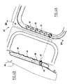
- Figure 4A shows a rear seat 40 showing tubular armatures 42 in which is formed a slot longitudinal 44 facing backwards and through which the free end said strap is adapted to extend.
- This free end is connected to a retention system 45 housed in the tubular reinforcement 42 and which is likely to slide there without being able to leave through the slot longitudinal 44.
- the free end is integral with the frames tubular 42 which then forms a rail.
- tubular armatures have pre-positioning points 46 formed by hollow deformations inside the tubular reinforcements 42, intended to block said end free in translation.
- these deformations are consistent concavely and the retaining system 45 is of spherical symmetry to partially accommodate at least in these deformations. So, when said restraint system 45 is housed in a deformation 46 and that the strap is pulled back, substantially perpendicularly tubular reinforcement 42, it is partially blocked in translation.
Landscapes
- Engineering & Computer Science (AREA)
- Mechanical Engineering (AREA)
- Seats For Vehicles (AREA)
- Supplying Of Containers To The Packaging Station (AREA)
- Sink And Installation For Waste Water (AREA)
- Photoreceptors In Electrophotography (AREA)
- Jellies, Jams, And Syrups (AREA)
- Registering, Tensioning, Guiding Webs, And Rollers Therefor (AREA)
Abstract
Description
- la Figure 1 est une vue schématique partielle en coupe verticale montrant une banquette arrière et un coffre de véhicule automobile dans laquelle est installé le dispositif conforme à l'invention dans une première position ;
- la Figure 2 est une vue schématique en coupe partielle montrant le dispositif conforme à l'invention dans une seconde position ;
- la Figure 3 est une vue schématique de dessus montrant la banquette et le coffre illustrés sur la Figure 1, et le dispositif dans ladite seconde position selon un mode particulier de mise en oeuvre;
- la Figure 4A est une vue schématique de face et arrière d'une banquette arrière selon une autre variante de réalisation ; et,
- la Figure 4B est une vue de profil en coupe selon le plan IVB-IVB illustré sur la Figure 4A.
Claims (9)
- Dispositif de retenue de charge adapté à maintenir une charge en appui contre au moins une paroi d'un coffre de véhicule automobile, ledit coffre étant délimité par une banquette arrière (10), ledit dispositif comprenant une sangle escamotable (22) dont une première extrémité est reliée à une portion de paroi dudit coffre, tandis qu'une seconde extrémité (25) est adaptée à être accrochée dans une autre portion de paroi dans une position de service pour maintenir ladite sangle escamotable (22) contre ladite charge ;
caractérisé en ce que ladite première extrémité de ladite sangle escamotable (22) présente une extrémité libre (24) qui est solidaire de ladite banquette arrière (10). - Dispositif de retenue de charge selon la revendication 1, caractérisé en ce que ladite banquette arrière comporte un rail de positionnement dans lequel ladite extrémité libre est adaptée à coulisser.
- Dispositif de retenue de charge selon la revendication 2, caractérisé en ce que ledit rail présente des points de pré-positionnement destinés à bloquer ladite extrémité libre en translation.
- Dispositif de retenue de charge selon la revendication 2 ou 3, caractérisé en ce que, ladite banquette arrière présentant une armature tubulaire, ledit rail est formé par ladite armature dans laquelle est ménagée une fente longitudinale.
- Dispositif de retenue de charge selon la revendication 1, caractérisé en ce que ladite banquette arrière (10) présente deux battants (12, 14) définissant deux tranches de banquette et en ce qu'elle comprend un logement (28) entre lesdites tranches, adapté à recevoir ladite sangle escamotable (22) dans une position escamotée.
- Dispositif de retenue de charge selon la revendication 5, caractérisé en ce que ladite extrémité libre (24) est adaptée à être reliée à un pivot (16) adapté au pivotement desdits battants (12,14).
- Dispositif de retenue de charge selon l'une quelconque des revendications 1 à 6, caractérisé en ce que ladite sangle escamotable (22) est élastiquement déformable longitudinalement,
- Dispositif de retenue de charge selon la revendication 7, caractérisé en ce que ladite sangle escamotable (22) est réalisée dans une matière plastique de type élastomère.
- Dispositif de retenue de charge selon l'une quelconque des revendications 1 à 8, caractérisé en ce que ladite seconde extrémité (25) présente des premiers moyens d'accrochage adaptés à coopérer avec des seconds moyens d'accrochage solidaires de ladite portion de paroi.
Applications Claiming Priority (2)
| Application Number | Priority Date | Filing Date | Title |
|---|---|---|---|
| FR0314936 | 2003-12-18 | ||
| FR0314936A FR2863978B1 (fr) | 2003-12-18 | 2003-12-18 | Dispositif de retenue de charge |
Publications (2)
| Publication Number | Publication Date |
|---|---|
| EP1544039A1 true EP1544039A1 (fr) | 2005-06-22 |
| EP1544039B1 EP1544039B1 (fr) | 2006-06-21 |
Family
ID=34508701
Family Applications (1)
| Application Number | Title | Priority Date | Filing Date |
|---|---|---|---|
| EP04300849A Expired - Lifetime EP1544039B1 (fr) | 2003-12-18 | 2004-12-06 | Dispositif de retenue de charge |
Country Status (5)
| Country | Link |
|---|---|
| EP (1) | EP1544039B1 (fr) |
| AT (1) | ATE330820T1 (fr) |
| DE (1) | DE602004001324T2 (fr) |
| ES (1) | ES2262106T3 (fr) |
| FR (1) | FR2863978B1 (fr) |
Citations (5)
| Publication number | Priority date | Publication date | Assignee | Title |
|---|---|---|---|---|
| FR2677592A1 (fr) * | 1991-06-17 | 1992-12-18 | Peugeot | Dispositif de maintien de charges, en particulier pour coffre de vehicule automobile. |
| DE29500366U1 (de) * | 1995-01-11 | 1995-03-02 | Maile, Björn, 70195 Stuttgart | Schnellbefestigungsvorrichtung für lose Gegenstände in Transportmitteln |
| EP0949119A1 (fr) * | 1998-04-09 | 1999-10-13 | Volkswagen Aktiengesellschaft | Dispositif pour la fixation de la charge dans un coffre de véhicule |
| US6007283A (en) * | 1997-06-17 | 1999-12-28 | Peter Butz Gmbh & Co. Verwaltungs-Kg | Motor-vehicle cargo restraint |
| DE10134887A1 (de) * | 2001-07-18 | 2003-02-27 | Daimler Chrysler Ag | Befestigungsvorrichtung zum Haltern und/oder Sichern von Gegenständen in einem Fahrzeugladeraum |
-
2003
- 2003-12-18 FR FR0314936A patent/FR2863978B1/fr not_active Expired - Fee Related
-
2004
- 2004-12-06 DE DE602004001324T patent/DE602004001324T2/de not_active Expired - Lifetime
- 2004-12-06 EP EP04300849A patent/EP1544039B1/fr not_active Expired - Lifetime
- 2004-12-06 AT AT04300849T patent/ATE330820T1/de not_active IP Right Cessation
- 2004-12-06 ES ES04300849T patent/ES2262106T3/es not_active Expired - Lifetime
Patent Citations (5)
| Publication number | Priority date | Publication date | Assignee | Title |
|---|---|---|---|---|
| FR2677592A1 (fr) * | 1991-06-17 | 1992-12-18 | Peugeot | Dispositif de maintien de charges, en particulier pour coffre de vehicule automobile. |
| DE29500366U1 (de) * | 1995-01-11 | 1995-03-02 | Maile, Björn, 70195 Stuttgart | Schnellbefestigungsvorrichtung für lose Gegenstände in Transportmitteln |
| US6007283A (en) * | 1997-06-17 | 1999-12-28 | Peter Butz Gmbh & Co. Verwaltungs-Kg | Motor-vehicle cargo restraint |
| EP0949119A1 (fr) * | 1998-04-09 | 1999-10-13 | Volkswagen Aktiengesellschaft | Dispositif pour la fixation de la charge dans un coffre de véhicule |
| DE10134887A1 (de) * | 2001-07-18 | 2003-02-27 | Daimler Chrysler Ag | Befestigungsvorrichtung zum Haltern und/oder Sichern von Gegenständen in einem Fahrzeugladeraum |
Also Published As
| Publication number | Publication date |
|---|---|
| DE602004001324T2 (de) | 2007-05-10 |
| FR2863978A1 (fr) | 2005-06-24 |
| EP1544039B1 (fr) | 2006-06-21 |
| DE602004001324D1 (de) | 2006-08-03 |
| FR2863978B1 (fr) | 2006-02-17 |
| ES2262106T3 (es) | 2006-11-16 |
| ATE330820T1 (de) | 2006-07-15 |
Similar Documents
| Publication | Publication Date | Title |
|---|---|---|
| EP1882608A2 (fr) | Siège automobile pour enfant, comprenant des moyens de guidage d'une sangle ventrale | |
| FR2962699A1 (fr) | Banquette pour vehicule utilitaire a espace de chargement utile allonge | |
| FR3061095A1 (fr) | Fauteuil comportant une tetiere reglable | |
| WO2015001247A2 (fr) | Système cache-bagages pour véhicule automobile | |
| EP1544039B1 (fr) | Dispositif de retenue de charge | |
| EP0741057B1 (fr) | Cache-bagages pour véhicule automobile | |
| FR2914595A3 (fr) | Agencement de rangement pour un element d'habitacle de vehicule automobile | |
| FR2745535A3 (fr) | Dispositif de fixation de siege-auto pour enfant par ceinture trois points dans les vehicules automobiles | |
| EP4419422B1 (fr) | Structure souple pour la création d'un espace de repos a l'intérieur d'une cabine d'aéronef | |
| FR2929898A3 (fr) | Cache bagage occultant a fixation elastique-ensemble permettant le montage d'un tel cache bagage | |
| EP2121363B1 (fr) | Dispositif de protection des sieges arriere d'un vehicule automobile du type cabriolet | |
| FR2964616A1 (fr) | Tendelet escamotable et structure arriere de vehicule automobile associee | |
| FR2928594A3 (fr) | Dispositif de maintien d'une canette de boisson et d'un telephone mobile | |
| FR3095999A1 (fr) | Support interne d’objet pour véhicule automobile. | |
| FR3022870A1 (fr) | Systeme de montage d’un cache-bagages de vehicule automobile | |
| FR2999495A1 (fr) | Tablette centrale et systeme de montage a liberation automatique de la tablette | |
| FR2950007A1 (fr) | Console amovible destinee a etre disposee dans une zone arriere d'habitacle d'un vehicule, equipee de sieges arriere | |
| FR2983811A1 (fr) | Siege pour vehicule de transport | |
| EP0223659A1 (fr) | Tablette arrière pour véhicule automobile et véhicule équipé de cette tablette | |
| FR3167083A1 (fr) | Vehicule du type quadricycle a moteur ou quadricycle leger, dote d’un dispositif enrouleur de forme tubulaire equipe d’une bâche | |
| FR2844228A1 (fr) | Siege escamotable comportant des butees d'appui en position d'utilisation | |
| FR2871751A1 (fr) | Agencement de tablette arriere de securite pour vehicule automobile | |
| FR2872465A1 (fr) | Agencement de planche de bord de vehicule automobile | |
| FR3141118A1 (fr) | Support de charge à l’intérieur d’un véhicule automobile. | |
| FR2950578A1 (fr) | Haut de siege embarque sur lunette arriere |
Legal Events
| Date | Code | Title | Description |
|---|---|---|---|
| PUAI | Public reference made under article 153(3) epc to a published international application that has entered the european phase |
Free format text: ORIGINAL CODE: 0009012 |
|
| AK | Designated contracting states |
Kind code of ref document: A1 Designated state(s): AT BE BG CH CY CZ DE DK EE ES FI FR GB GR HU IE IS IT LI LT LU MC NL PL PT RO SE SI SK TR |
|
| AX | Request for extension of the european patent |
Extension state: AL BA HR LV MK YU |
|
| 17P | Request for examination filed |
Effective date: 20050726 |
|
| GRAP | Despatch of communication of intention to grant a patent |
Free format text: ORIGINAL CODE: EPIDOSNIGR1 |
|
| GRAJ | Information related to disapproval of communication of intention to grant by the applicant or resumption of examination proceedings by the epo deleted |
Free format text: ORIGINAL CODE: EPIDOSDIGR1 |
|
| GRAP | Despatch of communication of intention to grant a patent |
Free format text: ORIGINAL CODE: EPIDOSNIGR1 |
|
| AKX | Designation fees paid |
Designated state(s): AT BE BG CH CY CZ DE DK EE ES FI FR GB GR HU IE IS IT LI LT LU MC NL PL PT RO SE SI SK TR |
|
| GRAS | Grant fee paid |
Free format text: ORIGINAL CODE: EPIDOSNIGR3 |
|
| GRAA | (expected) grant |
Free format text: ORIGINAL CODE: 0009210 |
|
| AK | Designated contracting states |
Kind code of ref document: B1 Designated state(s): AT BE BG CH CY CZ DE DK EE ES FI GB GR HU IE IS IT LI LT LU MC NL PL PT RO SE SI SK TR |
|
| PG25 | Lapsed in a contracting state [announced via postgrant information from national office to epo] |
Ref country code: IT Free format text: LAPSE BECAUSE OF FAILURE TO SUBMIT A TRANSLATION OF THE DESCRIPTION OR TO PAY THE FEE WITHIN THE PRESCRIBED TIME-LIMIT;WARNING: LAPSES OF ITALIAN PATENTS WITH EFFECTIVE DATE BEFORE 2007 MAY HAVE OCCURRED AT ANY TIME BEFORE 2007. THE CORRECT EFFECTIVE DATE MAY BE DIFFERENT FROM THE ONE RECORDED. Effective date: 20060621 Ref country code: RO Free format text: LAPSE BECAUSE OF FAILURE TO SUBMIT A TRANSLATION OF THE DESCRIPTION OR TO PAY THE FEE WITHIN THE PRESCRIBED TIME-LIMIT Effective date: 20060621 Ref country code: CZ Free format text: LAPSE BECAUSE OF FAILURE TO SUBMIT A TRANSLATION OF THE DESCRIPTION OR TO PAY THE FEE WITHIN THE PRESCRIBED TIME-LIMIT Effective date: 20060621 Ref country code: PL Free format text: LAPSE BECAUSE OF FAILURE TO SUBMIT A TRANSLATION OF THE DESCRIPTION OR TO PAY THE FEE WITHIN THE PRESCRIBED TIME-LIMIT Effective date: 20060621 Ref country code: SI Free format text: LAPSE BECAUSE OF FAILURE TO SUBMIT A TRANSLATION OF THE DESCRIPTION OR TO PAY THE FEE WITHIN THE PRESCRIBED TIME-LIMIT Effective date: 20060621 Ref country code: SK Free format text: LAPSE BECAUSE OF FAILURE TO SUBMIT A TRANSLATION OF THE DESCRIPTION OR TO PAY THE FEE WITHIN THE PRESCRIBED TIME-LIMIT Effective date: 20060621 Ref country code: LT Free format text: LAPSE BECAUSE OF FAILURE TO SUBMIT A TRANSLATION OF THE DESCRIPTION OR TO PAY THE FEE WITHIN THE PRESCRIBED TIME-LIMIT Effective date: 20060621 Ref country code: NL Free format text: LAPSE BECAUSE OF FAILURE TO SUBMIT A TRANSLATION OF THE DESCRIPTION OR TO PAY THE FEE WITHIN THE PRESCRIBED TIME-LIMIT Effective date: 20060621 Ref country code: FI Free format text: LAPSE BECAUSE OF FAILURE TO SUBMIT A TRANSLATION OF THE DESCRIPTION OR TO PAY THE FEE WITHIN THE PRESCRIBED TIME-LIMIT Effective date: 20060621 Ref country code: AT Free format text: LAPSE BECAUSE OF FAILURE TO SUBMIT A TRANSLATION OF THE DESCRIPTION OR TO PAY THE FEE WITHIN THE PRESCRIBED TIME-LIMIT Effective date: 20060621 Ref country code: IE Free format text: LAPSE BECAUSE OF FAILURE TO SUBMIT A TRANSLATION OF THE DESCRIPTION OR TO PAY THE FEE WITHIN THE PRESCRIBED TIME-LIMIT Effective date: 20060621 |
|
| REG | Reference to a national code |
Ref country code: GB Ref legal event code: FG4D Free format text: NOT ENGLISH |
|
| REG | Reference to a national code |
Ref country code: CH Ref legal event code: EP |
|
| REG | Reference to a national code |
Ref country code: IE Ref legal event code: FG4D Free format text: LANGUAGE OF EP DOCUMENT: FRENCH |
|
| REF | Corresponds to: |
Ref document number: 602004001324 Country of ref document: DE Date of ref document: 20060803 Kind code of ref document: P |
|
| GBT | Gb: translation of ep patent filed (gb section 77(6)(a)/1977) |
Effective date: 20060726 |
|
| PG25 | Lapsed in a contracting state [announced via postgrant information from national office to epo] |
Ref country code: SE Free format text: LAPSE BECAUSE OF FAILURE TO SUBMIT A TRANSLATION OF THE DESCRIPTION OR TO PAY THE FEE WITHIN THE PRESCRIBED TIME-LIMIT Effective date: 20060921 Ref country code: DK Free format text: LAPSE BECAUSE OF FAILURE TO SUBMIT A TRANSLATION OF THE DESCRIPTION OR TO PAY THE FEE WITHIN THE PRESCRIBED TIME-LIMIT Effective date: 20060921 |
|
| REG | Reference to a national code |
Ref country code: ES Ref legal event code: FG2A Ref document number: 2262106 Country of ref document: ES Kind code of ref document: T3 |
|
| PG25 | Lapsed in a contracting state [announced via postgrant information from national office to epo] |
Ref country code: PT Free format text: LAPSE BECAUSE OF FAILURE TO SUBMIT A TRANSLATION OF THE DESCRIPTION OR TO PAY THE FEE WITHIN THE PRESCRIBED TIME-LIMIT Effective date: 20061121 |
|
| NLV1 | Nl: lapsed or annulled due to failure to fulfill the requirements of art. 29p and 29m of the patents act | ||
| PG25 | Lapsed in a contracting state [announced via postgrant information from national office to epo] |
Ref country code: MC Free format text: LAPSE BECAUSE OF NON-PAYMENT OF DUE FEES Effective date: 20061231 Ref country code: BE Free format text: LAPSE BECAUSE OF NON-PAYMENT OF DUE FEES Effective date: 20061231 |
|
| REG | Reference to a national code |
Ref country code: IE Ref legal event code: FD4D |
|
| PLBE | No opposition filed within time limit |
Free format text: ORIGINAL CODE: 0009261 |
|
| STAA | Information on the status of an ep patent application or granted ep patent |
Free format text: STATUS: NO OPPOSITION FILED WITHIN TIME LIMIT |
|
| 26N | No opposition filed |
Effective date: 20070322 |
|
| BERE | Be: lapsed |
Owner name: RENAULT S.A.S. Effective date: 20061231 |
|
| PG25 | Lapsed in a contracting state [announced via postgrant information from national office to epo] |
Ref country code: GR Free format text: LAPSE BECAUSE OF FAILURE TO SUBMIT A TRANSLATION OF THE DESCRIPTION OR TO PAY THE FEE WITHIN THE PRESCRIBED TIME-LIMIT Effective date: 20060922 |
|
| PG25 | Lapsed in a contracting state [announced via postgrant information from national office to epo] |
Ref country code: EE Free format text: LAPSE BECAUSE OF FAILURE TO SUBMIT A TRANSLATION OF THE DESCRIPTION OR TO PAY THE FEE WITHIN THE PRESCRIBED TIME-LIMIT Effective date: 20060621 Ref country code: BG Free format text: LAPSE BECAUSE OF FAILURE TO SUBMIT A TRANSLATION OF THE DESCRIPTION OR TO PAY THE FEE WITHIN THE PRESCRIBED TIME-LIMIT Effective date: 20060921 |
|
| PG25 | Lapsed in a contracting state [announced via postgrant information from national office to epo] |
Ref country code: TR Free format text: LAPSE BECAUSE OF FAILURE TO SUBMIT A TRANSLATION OF THE DESCRIPTION OR TO PAY THE FEE WITHIN THE PRESCRIBED TIME-LIMIT Effective date: 20060621 Ref country code: LU Free format text: LAPSE BECAUSE OF NON-PAYMENT OF DUE FEES Effective date: 20061206 Ref country code: IS Free format text: LAPSE BECAUSE OF FAILURE TO SUBMIT A TRANSLATION OF THE DESCRIPTION OR TO PAY THE FEE WITHIN THE PRESCRIBED TIME-LIMIT Effective date: 20060621 Ref country code: HU Free format text: LAPSE BECAUSE OF FAILURE TO SUBMIT A TRANSLATION OF THE DESCRIPTION OR TO PAY THE FEE WITHIN THE PRESCRIBED TIME-LIMIT Effective date: 20061222 |
|
| PG25 | Lapsed in a contracting state [announced via postgrant information from national office to epo] |
Ref country code: CY Free format text: LAPSE BECAUSE OF FAILURE TO SUBMIT A TRANSLATION OF THE DESCRIPTION OR TO PAY THE FEE WITHIN THE PRESCRIBED TIME-LIMIT Effective date: 20060621 |
|
| REG | Reference to a national code |
Ref country code: CH Ref legal event code: PL |
|
| PG25 | Lapsed in a contracting state [announced via postgrant information from national office to epo] |
Ref country code: CH Free format text: LAPSE BECAUSE OF NON-PAYMENT OF DUE FEES Effective date: 20081231 Ref country code: LI Free format text: LAPSE BECAUSE OF NON-PAYMENT OF DUE FEES Effective date: 20081231 |
|
| PGFP | Annual fee paid to national office [announced via postgrant information from national office to epo] |
Ref country code: DE Payment date: 20161213 Year of fee payment: 13 Ref country code: GB Payment date: 20161222 Year of fee payment: 13 |
|
| PGFP | Annual fee paid to national office [announced via postgrant information from national office to epo] |
Ref country code: ES Payment date: 20161213 Year of fee payment: 13 |
|
| REG | Reference to a national code |
Ref country code: DE Ref legal event code: R119 Ref document number: 602004001324 Country of ref document: DE |
|
| GBPC | Gb: european patent ceased through non-payment of renewal fee |
Effective date: 20171206 |
|
| PG25 | Lapsed in a contracting state [announced via postgrant information from national office to epo] |
Ref country code: DE Free format text: LAPSE BECAUSE OF NON-PAYMENT OF DUE FEES Effective date: 20180703 |
|
| PG25 | Lapsed in a contracting state [announced via postgrant information from national office to epo] |
Ref country code: GB Free format text: LAPSE BECAUSE OF NON-PAYMENT OF DUE FEES Effective date: 20171206 |
|
| REG | Reference to a national code |
Ref country code: ES Ref legal event code: FD2A Effective date: 20190702 |
|
| PG25 | Lapsed in a contracting state [announced via postgrant information from national office to epo] |
Ref country code: ES Free format text: LAPSE BECAUSE OF NON-PAYMENT OF DUE FEES Effective date: 20171207 |