EP1543877B1 - Analyzer and reagent container - Google Patents
Analyzer and reagent container Download PDFInfo
- Publication number
- EP1543877B1 EP1543877B1 EP03028679A EP03028679A EP1543877B1 EP 1543877 B1 EP1543877 B1 EP 1543877B1 EP 03028679 A EP03028679 A EP 03028679A EP 03028679 A EP03028679 A EP 03028679A EP 1543877 B1 EP1543877 B1 EP 1543877B1
- Authority
- EP
- European Patent Office
- Prior art keywords
- reagent
- connectional
- container
- passage
- reagent container
- Prior art date
- Legal status (The legal status is an assumption and is not a legal conclusion. Google has not performed a legal analysis and makes no representation as to the accuracy of the status listed.)
- Expired - Lifetime
Links
- 239000003153 chemical reaction reagent Substances 0.000 title claims abstract description 210
- 230000000903 blocking effect Effects 0.000 claims abstract description 19
- 239000012491 analyte Substances 0.000 claims abstract description 4
- 210000000601 blood cell Anatomy 0.000 claims description 17
- 230000002949 hemolytic effect Effects 0.000 claims description 7
- 230000006835 compression Effects 0.000 description 19
- 238000007906 compression Methods 0.000 description 19
- 238000003780 insertion Methods 0.000 description 10
- 230000037431 insertion Effects 0.000 description 10
- 239000011347 resin Substances 0.000 description 9
- 229920005989 resin Polymers 0.000 description 9
- 239000011800 void material Substances 0.000 description 9
- 230000014759 maintenance of location Effects 0.000 description 6
- 239000002184 metal Substances 0.000 description 6
- 229920001971 elastomer Polymers 0.000 description 5
- 230000008602 contraction Effects 0.000 description 2
- 239000011096 corrugated fiberboard Substances 0.000 description 2
- 210000003743 erythrocyte Anatomy 0.000 description 2
- 230000002093 peripheral effect Effects 0.000 description 2
- 229910052710 silicon Inorganic materials 0.000 description 2
- 239000010703 silicon Substances 0.000 description 2
- 229920006346 thermoplastic polyester elastomer Polymers 0.000 description 2
- 229930182556 Polyacetal Natural products 0.000 description 1
- 239000004698 Polyethylene Substances 0.000 description 1
- 238000004873 anchoring Methods 0.000 description 1
- 230000000694 effects Effects 0.000 description 1
- 210000000265 leukocyte Anatomy 0.000 description 1
- 238000000034 method Methods 0.000 description 1
- 239000004033 plastic Substances 0.000 description 1
- 229920003023 plastic Polymers 0.000 description 1
- -1 polyethylene Polymers 0.000 description 1
- 229920000573 polyethylene Polymers 0.000 description 1
- 229920006324 polyoxymethylene Polymers 0.000 description 1
Images


Classifications
-
- G—PHYSICS
- G01—MEASURING; TESTING
- G01N—INVESTIGATING OR ANALYSING MATERIALS BY DETERMINING THEIR CHEMICAL OR PHYSICAL PROPERTIES
- G01N35/00—Automatic analysis not limited to methods or materials provided for in any single one of groups G01N1/00 - G01N33/00; Handling materials therefor
- G01N35/10—Devices for transferring samples or any liquids to, in, or from, the analysis apparatus, e.g. suction devices, injection devices
- G01N35/1002—Reagent dispensers
Definitions
- the present invention relates to an analyzer and a reagent container, and more particularly, it relates to an analyzer analyzing an analyte with a reagent and a reagent container.
- a structure obtained by connecting a reagent container for storing an analytical reagent employed in a clinical test apparatus with the clinical test apparatus through a tube is known in general.
- Such a structure is disclosed in Japanese Patent Laying-Open No. 9-297146 (1997 ), for example.
- a flexible tube is connected to an opening of the reagent container, in which a suction pipe is arranged. The suction pipe sucks the reagent stored in the reagent container for supplying the sucked reagent to the clinical test apparatus through the tube mounted on the opening of the reagent container.
- the reagent When the reagent is almost used up and the tube is detached from the reagent container for exchanging the same in the aforementioned structure disclosed in Japanese Patent Laying-Open No. 9-297146 , however, the reagent partially remaining in the reagent container or the tube disadvantageously comes into contact with the air. If the reagent coming into contact with the air is a reagent hemolyzing blood cells which is giving off a malodor, for example, the user of the reagent disadvantageously breathes in such a malodor when exchanging the reagent container.
- An object of the present invention is to provide an analyzer enabling the user to hardly breathe in a malodor given off from a reagent when exchanging a reagent container.
- Another object of the present invention is to provide a reagent container enabling the user to hardly breathe in a malodor given off from a reagent stored therein when exchanging the reagent container.
- a further object is to provide an analyzer in combination with a reagent container.
- an analyzer to be connected with a reagent container, comprises an analyzer body for analyzing an analyte with the reagent and reagent transport means having a first end connected to the analyzer body and a second end connected to the reagent container.
- the reagent transport means includes a first connectional part, detachably connectable to the reagent container, having a first switching member forming and blocking a first passage between the analyzer body and the reagent container. The first switching member blocks the first passage when the first connectional part is separated from the reagent container, and forms the first passage when the first connectional part is connected to the reagent container.
- the analyzer according to the first aspect is provided with the first connectional part having the first switching member forming and blocking the first passage between the analyzer body and the reagent container while the first switching member is so structured as to block the first passage when the first connectional part is separated from the reagent container and form the first passage when the first connectional part is connected to the reagent container, whereby the first switching part blocks the first passage between the analyzer body and the reagent container when the first connectional part is separated from the reagent container for exchanging the reagent container and hence the reagent partially remaining in the reagent container and the reagent transport means can be inhibited from coming into contact with the air when the reagent container is exchanged. Even if the reagent gives off a malodor when coming into contact with the air, therefore, the user of the analyzer hardly breathes in such a malodor when exchanging the reagent container.
- the first switching member preferably moves to a position for blocking the first passage with the urging force of a first elastic member when the first connectional part is separated from the reagent container, and preferably moves to an opposite direction against the urging force of the first elastic member for forming the first passage when the first connectional part is connected to the reagent container.
- the first switching member can automatically block the first passage between the analyzer body and the reagent container with the urging force of the first elastic member when the first connectional part is separated from the reagent container for exchanging the reagent container.
- the aforementioned analyzer according to the first aspect is combined with a reagent container which includes a second connectional part detachably connected to the first connectional part, and the first connectional part includes a recess portion at least partially storing the second connectional part of the reagent container, a fixing member mounted to be capable of advancing in/retreating from the recess portion for fixing the second connectional part of the reagent container to the first connectional part and a pressing member movably mounted with respect to the recess portion for pressing the fixing member into the recess portion on a first position while canceling the pressing against the fixing member on a second position.
- the first connectional part can be easily detachably connected to the second connectional part of the reagent container by moving the pressing member to the first position and the second position.
- a second elastic member preferably urges the pressing member with its urging force to locate the pressing member on the first position for pressing the fixing member.
- the first connectional part can be kept mounted/fixed on/to the second connectional part of the reagent container with the urging force of the second elastic member.
- the reagent transport means preferably includes a sensor for determining presence/nonpresence of the reagent in the container body. According to this structure, it is possible to easily detect that the reagent is used up and the container body must be exchanged.
- the senor preferably includes a light source part applying light to the first passage and a photodetector receiving the light from the light source part. According to this structure, presence/nonpresence of the reagent can be easily detected through the light source part and the photodetector.
- the aforementioned analyzer according to the first aspect is combined with a reagent container which includes a second connectional part provided on an opening of the aforementioned flexible container body and detachably connected to the first connectional part, the second connectional part includes a second switching member forming and blocking a second passage between the reagent transport means and the container body, and the second switching member blocks the second passage when the second connectional part is separated from the first connectional part, and forms the second passage when the second connectional part is connected to the first connectional part.
- the second switching member blocks the second passage between the reagent transport means and the container body when the second connectional part is separated from the first connectional part for exchanging the reagent container, whereby the reagent partially remaining in the container body can be inhibited from coming into contact with the external air when the reagent container is exchanged. Even if the reagent gives off a malodor when coming into contact with the air, therefore, the user hardly breathes in such a malodor.
- the connectional part includes a switching member forming and blocking a passage between the reagent transport means and the container body, and the switching member blocks the passage when the connectional part is separated from the reagent transport means, and forms the passage when the connectional part is connected to the reagent transport means.
- the reagent container according to the second aspect is provided with the connectional part including the switching member forming and blocking the passage between the reagent transport means and the container body while the switching member is so structured as to block the passage when the connectional part is separated from the reagent transport means and form the passage when the connectional part is connected to the reagent transport means, whereby the switching part blocks the passage between the reagent transport means and the container body when the connectional part is separated from the reagent transport means of the analyzer for exchanging the reagent container and hence the reagent partially remaining in the container body can be inhibited from coming into contact with the external air when the reagent container is exchanged. Even if the reagent gives off a malodor when coming into contact with the air, therefore, the user of the reagent container hardly breathes in such a malodor when exchanging the container body.
- the switching member preferably moves to a position for blocking the passage with the urging force of an elastic member when the connectional part is separated from the reagent transport means, and preferably moves to an opposite direction against the urging force of the elastic member for forming the passage when the connectional part is connected to the reagent transport means.
- the container body preferably includes a flexible tube connected to the connectional part therein. According to this structure, it is possible to deform the tube in response to the degree of contraction of the flexible container body, whereby the reagent can be easily transported to the reagent transport means through the tube also when the volume of the reagent remaining in the container body is reduced.
- the container body includes an anchor, mounted on the forward end of the tube, having a hole for sucking the reagent. According to this structure, the forward end of the tube can be regularly positioned on the bottom of the container body while the reagent can be sucked through the hole of the anchor.
- the aforementioned reagent container according to the second aspect preferably further comprises a box storing the container body.
- the aforementioned box can inhibit the flexible container body storing the reagent from damage caused by external force.
- the reagent preferably includes a reagent hemolyzing blood cells.
- a reagent hemolyzing blood cells may give off a malodor when coming into contact with the air.
- the user With the reagent container according to the present invention, however, the user hardly breathes in such a malodor when exchanging the reagent container.
- the flexible container body preferably consists of a bag contracting in response to the residual quantity of the reagent.
- the container body may be provided with no air hole, whereby the reagent stored in the container body can be more reliably prevented from coming into contact with the air.
- the aforementioned reagent container according to the second aspect preferably further comprises the reagent stored in the container body.
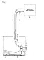
- a blood cell analyzer and a reagent container according to the embodiment of the present invention are described with reference to Fig. 1 .
- the analyzer and the reagent container according to the present invention are applied to the blood cell analyzer and the reagent container employed for this blood cell analyzer.
- the reagent container stores a reagent for hemolyzing red blood cells employed for measuring immature white blood cells in the blood cell analyzer according to this embodiment.
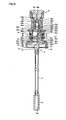
- the blood cell analyzer body 12 and a container body 1 consisting of a flexible bag for storing the reagent for hemolyzing red blood cells are connected with each other through flexible tubes 8 and 10 of silicon, as shown in Fig. 1 .
- the container body 1 contracts as shown in Fig. 2 without incorporating the outside air.
- the forward end of the tube 8 is connected to a socket 4, which in turn is connected to a plug 3.
- the plug 3 is an example of the "second connectional part” or the "connectional part” in the present invention
- the socket 4 is an example of the "first connectional part" or the "reagent transport means" in the present invention.
- the plug 3 is mounted on the container body 1 through a cap screw 2. Still another flexible tube 5 of silicon is arranged in the container body 1 for sucking the reagent.
- the tube 5 has a first end connected to the plug 3 and a second end mounted with an anchor 6 of resin. This anchor 6 is provided for regularly positioning the forward end of the tube 5 on the bottom of the container body 1.
- a bubble sensor 9 is arranged between the tubes 8 and 10, in order to detect presence/nonpresence of the reagent supplied from the tube 8 to the tube 10.
- the tubes 8 and 10 are examples of the "reagent transport means” in the present invention, and the bubble sensor 9 is an example of the "sensor” or the “reagent transport means” in the present invention.
- a power supply line 11 from the blood cell analyzer body 12 is connected to the bubble sensor 9.
- the tube 10 is provided with a check valve 13 for preventing the reagent from regurgitating from the blood cell analyzer body 12 to the tube 10.
- the container body 1 of the reagent container is stored in a corrugated fiberboard box 7.
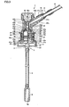
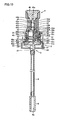
- cap screw 2 The structures of the cap screw 2, the plug 3, the socket 4, the tube 5 and the anchor 6 are now described in detail with reference to Figs. 3 to 7 .
- the socket 4 includes a connectional part 41, a body part 42 of resin, a switching member 43 of resin, O-rings 44a and 44b of rubber, a helical compression spring 45 of a metal, a lid member 46 of resin, balls 47 of a metal, a pressing member 48 of resin and another helical compression spring 49 of a metal.
- the connectional part 41 is provided with a screw part 41a and a reagent supply hole 41b.
- a tube joint member 14 of a metal is mounted on the forward end of the connectional part 41.
- the tube joint member 14 is fixed by fitting a fixing nut 15 with the screw part 41a of the connectional part 41.
- the tube 8 is engaged with the forward end of the tube joint member 14.
- the body part 42 of the socket 4 is provided with a recess portion 42a for receiving the plug 3.
- a void 42d is provided above the recess portion 42a through a passage forming hole 42b.
- a switching member 43 of resin is vertically movably arranged in the passage forming hole 42b and the void 42d.
- the switching member 43 is arranged to be movable between a lower position for closing the passage forming hole 42b and blocking a passage and an upper position for opening the passage forming hole 42b and forming the passage.
- the switching member 43 is an example of the "first switching member" in the present invention.
- a cylindrical forward end 43a of the switching member 43 closer to the void 42a comes into contact with the plug 3, as shown in Fig. 3 .
- the switching member 43 is also provided with a tapered part 43b continuous with the forward end 43a.
- the tapered part 43b has a shape capable of blocking the passage forming hole 42b.
- the aforementioned O-ring 44a of rubber is arranged between the tapered part 43b and a flange part 43c. This O-ring 44a has a function of preventing the reagent from leaking from the passage forming hole 42b blocked with the tapered part 43b toward the void 42a.
- the switching member 43 is further provided with a barrel 43d continuous with the flange part 43c and a forward end 43e, closer to the lid member 46 and continuous with the barrel 43d, having a smaller diameter than the barrel 43d.
- the forward end 43e closer to the lid member 46 is vertically movably inserted in an insertion hole 46a of the lid member 46.
- the aforementioned helical compression spring 45 is arranged between the flange part 43c and the lid member 46.
- the helical compression spring 45 is an example of the "first elastic member” in the present invention. This helical compression spring 45 is arranged to urge the tapered part 43b of the switching member 43 and the O-ring 44a to the lower position for closing the passage forming hole 42b.
- the O-ring 44b is arranged between the lower surface of the lid member 46 arranged in the void 42d of the body part 42 and the body part 42, in order to prevent the reagent from leaking from between the lid member 46 and the body part 42.
- the body part 42 is provided with a hole 42e for connecting the void 42d and the supply hole 41b of the connectional part 41 with each other.
- Ball retention holes 42c are provided on prescribed portions of the recess portion 42a of the body part 42.
- the aforementioned balls 47 of a metal are mounted in the ball retention holes 42c to be able to advance in/retreat from the recess portion 42a.
- the ball retention holes 42c have octagonal openings, and the balls 47 have diameters incapable of passing through the ball retention holes 42c.
- the balls 47 are arranged between the body part 42 and the pressing member 48, not to drop also when the socket 4 is detached from the plug 3. While the ball retention holes 42c may alternatively have circular openings, polygonal openings capable of preventing the balls 47 from anchoring to the ball retention holes 42c, are more preferable.
- the balls 47 are examples of the "fixing member" in the present invention.
- the aforementioned pressing member 48 is provided outside the position of the body part 42 formed with the recess portion 42a, in order to press the balls 47 into the recess portion 42a.
- This pressing member 48 presses the balls 47 when located on a lower position while canceling the pressing against the balls 47 when located on an upper position.
- the pressing member 48 is provided with a grip part 48b easily graspable for vertically moving the pressing member 48.
- the aforementioned helical compression spring 49 is provided between the outer peripheral surface of the body part 42 and the inner peripheral surface of the pressing member 48, in order to urge the pressing member 48 downward.
- the helical compression spring 49 is an example of the "second elastic member" in the present invention.
- the body part 42 is further provided with a stopper 42f coming into contact with a pressing part 48a of the downwardly urged pressing member 48.
- the pressing part 48a of the pressing member 48 is arranged on the lower position for pressing the balls 47 with the urging force of the helical compression spring 49.
- the cap screw 2 includes a screw part 21 formed on its inner surface, a lower hole 22, an upper hole 23 and a protruding portion 24 formed on its outer side surface.
- the plug 3 includes a tube joint part 31, a flange part 32, an insertion part 33, an O-ring 34 of rubber, a switching member 35, a helical compression spring 36 of a metal and a support part 37.
- the tube joint part 31, the flange part 32, the insertion part 33 and the support part 37 are made of resin such as polyethylene or polyacetal.
- the switching member 35 consists of thermoplastic polyester elastomer such as Hytrel by Du Pont-Toray Co., Ltd., for example. This thermoplastic polyester elastomer has intermediate softness between those of rubber and plastic.
- the tube joint part 31 of the plug 3 is constituted of a plurality of tapered parts capable of connecting the tube 5.
- the flange part 32 is formed to be integrally continuous with the tube joint part 31. As shown in Fig. 3 , the flange part 32 is engaged with the upper hole 23 of the cap screw 2.
- the insertion part 33 is formed to be integrally continuous with the flange part 32. As shown in Fig. 3 , the insertion part 33 is inserted into the recess portion 42a of the body part 42 of the socket 4.
- the insertion part 33 is provided with a fixing groove 33a and an O-ring receiving groove 33b.
- the fixing groove 33a has a width smaller than the outer diameter of the balls 47 of the socket 4, and both ends of this fixing groove 33a closer to an opening are chamfered.
- the aforementioned O-ring 34 of rubber is arranged in the O-ring receiving groove 33b. As shown in Fig. 3 , this O-ring 34 is provided for preventing the reagent from leaking from the recess portion 42a when the insertion part 33 of the plug 3 is inserted in the recess portion 42a of the socket 4.
- the plug 3 is provided therein with a void 33c and a passage forming hole 33d formed above the void 33c.
- the void 33c is provided therein with the aforementioned support part 37 having a hole 37a vertically movably receiving a shank 35d of the aforementioned switching member 35.
- the switching member 35 is movable between a position for closing the passage forming hole 33d and blocking a passage and a position for opening the passage forming hole 33d and forming the passage.
- the switching member 35 is an example of the "second switching member" in the present invention.
- the switching member 35 is provided on its upper end with a contact part 35a coming into contact with the forward end 43a of the switching member 43 of the socket 4.
- a tapered part 35b is formed to be continuous with the contact part 35a.
- This tapered part 35b has a shape capable of blocking the passage forming hole 33d from inside.
- the switching member 35 is also provided with a flange part 35c.
- the helical compression spring 36 is arranged between the flange part 35c and the support part 37.
- the helical compression spring 36 has a function of urging the tapered part 35b to block the passage forming hole 33d.
- the helical compression spring 36 is an example of the "elastic member" in the present invention.
- the anchor 6 of resin connected to an end of the tube 5 is provided with a hole 6a for sucking the reagent.
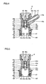
- the recess portion 42a of the socket 4 is engaged with the insertion part 33 of the plug 3 while the pressing member 48 is elevated in the aforementioned manner, to attain the state shown in Fig. 9 .
- the contact part 35a of the switching member 35 of the plug 3 is pushed down by the forward end 43a of the switching member 43 of the socket 4 while the forward end 43a of the switching member 43 of the socket 4 is pushed up due to reaction from the contact part 35a of the switching member 35 of the plug 3.
- both of the passage forming holes 42b and 33d of the socket 4 and the plug 3 are opened to form the passages.
- the O-ring 34 mounted on the insertion part 33 of the plug 3 comes into close contact with the inner surface of the recess portion 42a of the socket 4, thereby preventing the reagent from leaking from the recess portion 42a.
- the pressing member 48 is returned downward for urging the helical compression spring 49 as shown in Fig. 10 , so that the pressing part 48a of the pressing member 48 externally presses the balls 47 inward.
- the balls 47 move into the recess portion 42a to engage with the fixing groove 33a of the insertion part 33 of the plug 3, thereby fixing the plug 3 and the socket 4 to each other.
- the socket 4 is attached to the plug 3.
- the socket 4 is detached from the plug 3 contrarily to the above attaching operation.
- the grip part 48b of the pressing member 48 is elevated from the state shown in Fig. 10 thereby moving up the pressing member 48 as shown in Fig. 9 , for extracting the socket 4 upward from the plug 3.
- the switching member 35 of the plug 3 closes the passage forming hole 33d with the urging force of the helical compression spring 36 while the switching member 43 of the socket 4 also closes the passage forming hole 42b with the urging force of the helical compression .spring 45, as shown in Fig. 8 .
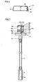
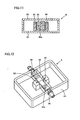
- the bubble sensor 9 shown in Fig. 1 is now described in detail with reference to Figs. 11 and 12 .
- a light-emitting diode 93 and a photodetector 94 are oppositely arranged in a case 91 of resin at a prescribed interval.
- the light-emitting diode 93 is an example of the "light source part" in the present invention.
- a square pole-shaped light-transmittable transparent member 95 having an elongated passage 95a is arranged between the light-emitting diode 93 and the photodetector 94.
- Joint members 96 are provided on both ends of the transparent member 95, in order to connect the tubes 8 and 10 (see Fig. 1 ) with the bubble sensor 9.
- a lid 92 is mounted on the upper portion of the case 91.
- a method of detecting presence/nonpresence of the reagent flowing through the passage 95a with the light-emitting diode 93 and the photodetector 94 is described with reference to Fig. 11 .
- the photodetector 94 receives no light from the light-emitting diode 93.
- the photodetector 94 receives the light from the light-emitting diode 93.
- the photodetector 94 determines whether or not the reagent is present in the passage 95a by determining whether or not the photodetector 94 receives the light from the light-emitting diode 93. If the photodetector 94 receives no light from the light-emitting diode 93 although the blood cell analyzer body 12 operates to suck the reagent from the container body 1, it is determined that the reagent stored in the container body 1 is used up.
- the socket 4 is provided with the switching member 43 blocking the passage when the socket 4 is separated from the plug 3 while forming the passage when the socket 4 is connected with the plug 3 and the plug 3 is provided with the switching member 35 blocking the passage when the plug 3 is separated from the socket 4 while forming the passage when the plug 3 is connected with the socket 4 as described above.
- the passages are so blocked that the reagent partially remaining in the container body 1 and the tube 8 can be inhibited from coming into contact with the air.
- employing the reagent for hemolyzing blood cells giving off a malodor when coming into contact with the air, therefore, the user hardly breathes in such a malodor when exchanging the container body 1.
- the switching member 43 of the socket 4 is so structured as to block the passage with the urging force of the helical compression spring 45 while the switching member 35 of the plug 3 is also so structured as to block the passage with the urging force of the helical compression spring 36, whereby the passages formed between the plug 3 and the socket 4 can be automatically blocked with the urging force of the helical compression springs 36 and 45 when the socket 4 is detached from the plug 3 mounted on the container body 1.
- the pressing member 48 is so provided on the socket 4 as to press the balls 47 on the lower position and cancel the pressing against the balls 47 on the upper position as hereinabove described, whereby the socket 4 can be easily detachably connected to the plug 3.
- the socket 4 can be easily kept attached and fixed to the plug 3 by urging the pressing member 48 to the lower position for pressing the balls 47 with the urging force of the helical compression spring 49.
- the bubble sensor 9 detecting presence/nonpresence of the reagent is provided for detecting presence/nonpresence of the reagent in the passage 95a as hereinabove described, whereby it is possible to easily detect that the reagent stored in the container body 1 is used up and the container body 1 must be exchanged.
- the flexible tube 5 is arranged in the container body 1 as hereinabove described, whereby the tube 5 can be deformed in response to the degree of contraction of the flexible container body 1 so that the reagent can be easily sucked through the tube 5 also when the volume of the reagent stored in the container body 1 is reduced.
- the anchor 6 having the hole 6a for sucking the reagent is mounted on the forward end of the tube 5, so that the forward end of the tube 5 can be regularly positioned on the bottom of the container body 1 and the reagent can be sucked through the hole 6a of the anchor 6.
- the container body 1 is arranged in the corrugated fiberboard box 7 as hereinabove described, whereby the flexible container body 1 storing the reagent can be inhibited from damage caused by external force.
- the container body 1 is constituted of the bag contracting in response to the residue of the reagent so that the container body 1 may be provided with no air hole as hereinabove described, whereby the reagent stored in the container body 1 can be further reliably prevented from coming into contact with the air.
- the present invention is not restricted to this but is also applicable to an analyzer body, other than the blood cell analyzer body 12, employing a reagent.
- the present invention is effective for employing a reagent giving off a malodor when coming into contact with the air.
- bubble sensor 9 consists of the light-.emitting diode 93 and the photodetector 94 in the aforementioned embodiment
- the present invention is not restricted to this but another sensor capable of detecting presence/nonpresence of a reagent may alternatively be employed.
- the present invention is not restricted to this but a similar effect can also be attained by employing fixing members having shapes other than those of balls.
Landscapes
- Physics & Mathematics (AREA)
- Health & Medical Sciences (AREA)
- Life Sciences & Earth Sciences (AREA)
- Chemical & Material Sciences (AREA)
- Analytical Chemistry (AREA)
- Biochemistry (AREA)
- General Health & Medical Sciences (AREA)
- General Physics & Mathematics (AREA)
- Immunology (AREA)
- Pathology (AREA)
- Investigating Or Analysing Biological Materials (AREA)
- Automatic Analysis And Handling Materials Therefor (AREA)
Priority Applications (5)
| Application Number | Priority Date | Filing Date | Title |
|---|---|---|---|
| DE60331748T DE60331748D1 (de) | 2003-12-16 | 2003-12-16 | Analysevorrichtung und Reagenzbehälter |
| AT03028679T ATE460986T1 (de) | 2003-12-16 | 2003-12-16 | Analysevorrichtung und reagenzbehälter |
| EP03028679A EP1543877B1 (en) | 2003-12-16 | 2003-12-16 | Analyzer and reagent container |
| JP2004353685A JP4512480B2 (ja) | 2003-12-16 | 2004-12-07 | 分析装置および試薬容器 |
| US11/013,993 US8017092B2 (en) | 2003-12-16 | 2004-12-16 | Analyzer and reagent container |
Applications Claiming Priority (1)
| Application Number | Priority Date | Filing Date | Title |
|---|---|---|---|
| EP03028679A EP1543877B1 (en) | 2003-12-16 | 2003-12-16 | Analyzer and reagent container |
Publications (2)
| Publication Number | Publication Date |
|---|---|
| EP1543877A1 EP1543877A1 (en) | 2005-06-22 |
| EP1543877B1 true EP1543877B1 (en) | 2010-03-17 |
Family
ID=34486200
Family Applications (1)
| Application Number | Title | Priority Date | Filing Date |
|---|---|---|---|
| EP03028679A Expired - Lifetime EP1543877B1 (en) | 2003-12-16 | 2003-12-16 | Analyzer and reagent container |
Country Status (5)
| Country | Link |
|---|---|
| US (1) | US8017092B2 (enExample) |
| EP (1) | EP1543877B1 (enExample) |
| JP (1) | JP4512480B2 (enExample) |
| AT (1) | ATE460986T1 (enExample) |
| DE (1) | DE60331748D1 (enExample) |
Families Citing this family (9)
| Publication number | Priority date | Publication date | Assignee | Title |
|---|---|---|---|---|
| CA2548220A1 (en) * | 2003-12-01 | 2005-09-09 | Introgen Therapeutics, Inc. | Use of mda-7 to inhibit infection by pathogenic organisms |
| JP4297922B2 (ja) * | 2006-06-27 | 2009-07-15 | 株式会社日立ハイテクノロジーズ | キャピラリ電気泳動装置 |
| CA2697645A1 (en) * | 2007-08-29 | 2009-03-05 | Dako Denmark A/S | On-site liquid production |
| KR100886914B1 (ko) * | 2007-11-01 | 2009-03-09 | 주식회사 아이센스 | 혈액 분석 장치용 카트리지 및 이를 이용한 혈액 분석 장치 |
| KR100873915B1 (ko) * | 2007-11-01 | 2008-12-12 | 주식회사 아이센스 | 혈액 분석 장치용 용액 용기 |
| JP5789404B2 (ja) | 2011-04-22 | 2015-10-07 | シスメックス株式会社 | 試薬容器 |
| JP6116124B2 (ja) | 2012-03-15 | 2017-04-19 | シスメックス株式会社 | 生体試料分析装置用の試薬容器及び試薬容器の製造方法 |
| JP6385800B2 (ja) | 2014-11-11 | 2018-09-05 | 日本電子株式会社 | 液体吸引具、液体供給ユニット及び自動分析装置 |
| CN115541913A (zh) * | 2022-09-29 | 2022-12-30 | 时新(上海)产品设计有限公司 | 加样机构及包含其的加样系统 |
Family Cites Families (19)
| Publication number | Priority date | Publication date | Assignee | Title |
|---|---|---|---|---|
| US3729023A (en) * | 1972-01-26 | 1973-04-24 | Hansen Mfg Co | Coupling assembly |
| US3851666A (en) * | 1973-03-09 | 1974-12-03 | Hansen Mfg Co | Coupling assembly |
| US3953136A (en) * | 1974-03-15 | 1976-04-27 | Hach Chemical Company | Method and apparatus for automatically analyzing fluids |
| DE3513205C1 (de) * | 1985-04-12 | 1987-01-15 | Fresenius Ag | Konnektor fuer die Peritonealdialyse |
| CH672363A5 (enExample) * | 1986-09-29 | 1989-11-15 | Contempo Products | |
| JPS6399852A (ja) | 1986-10-16 | 1988-05-02 | アロカ株式会社 | 超音波破砕装置 |
| JPS6399852U (enExample) * | 1986-12-18 | 1988-06-28 | ||
| JPH04145289A (ja) * | 1990-10-08 | 1992-05-19 | Fujitsu Ltd | セルフシール管継手 |
| US5207645A (en) * | 1991-06-25 | 1993-05-04 | Medication Delivery Devices | Infusion pump, treatment fluid bag therefor, and method for the use thereof |
| JP3302080B2 (ja) | 1993-03-19 | 2002-07-15 | 株式会社東芝 | 自動分析装置 |
| FR2723735B1 (fr) * | 1994-08-18 | 1996-10-31 | Abx Sa | Boitier a branchement automatique pour distribution de reactifs dans un appareil notamment un analyseur hematologique. |
| JP3479380B2 (ja) | 1995-03-31 | 2003-12-15 | シスメックス株式会社 | 液体吸引装置 |
| US5570815A (en) * | 1995-06-06 | 1996-11-05 | International Business Machine Corp. | Chemical delivery system |
| US6250130B1 (en) * | 1995-07-10 | 2001-06-26 | Bayer Corporation | Method and apparatus for monitoring an aspirating and dispensing system |
| JP2758148B2 (ja) * | 1995-08-14 | 1998-05-28 | 日機装株式会社 | 血液浄化器用カプラ |
| JPH09297146A (ja) | 1996-05-02 | 1997-11-18 | Toa Medical Electronics Co Ltd | 液体吸引装置 |
| DE19914536A1 (de) * | 1999-03-31 | 2000-10-05 | Bayerische Motoren Werke Ag | Scheibenwischanlage |
| US6810923B2 (en) * | 2000-01-04 | 2004-11-02 | Biodevices, Inc. | Pipet for liquid exchange |
| JP4458644B2 (ja) * | 2000-08-21 | 2010-04-28 | サーパス工業株式会社 | 接続器具 |
-
2003
- 2003-12-16 EP EP03028679A patent/EP1543877B1/en not_active Expired - Lifetime
- 2003-12-16 DE DE60331748T patent/DE60331748D1/de not_active Expired - Lifetime
- 2003-12-16 AT AT03028679T patent/ATE460986T1/de not_active IP Right Cessation
-
2004
- 2004-12-07 JP JP2004353685A patent/JP4512480B2/ja not_active Expired - Fee Related
- 2004-12-16 US US11/013,993 patent/US8017092B2/en not_active Expired - Fee Related
Also Published As
| Publication number | Publication date |
|---|---|
| EP1543877A1 (en) | 2005-06-22 |
| US20050191211A1 (en) | 2005-09-01 |
| JP4512480B2 (ja) | 2010-07-28 |
| DE60331748D1 (de) | 2010-04-29 |
| US8017092B2 (en) | 2011-09-13 |
| ATE460986T1 (de) | 2010-04-15 |
| JP2005181309A (ja) | 2005-07-07 |
Similar Documents
| Publication | Publication Date | Title |
|---|---|---|
| EP1543877B1 (en) | Analyzer and reagent container | |
| JP4319590B2 (ja) | 採便容器 | |
| US8367024B2 (en) | Test tube holder | |
| JP2004501745A (ja) | 自動ピペット識別および先端部取外し | |
| US6680027B2 (en) | Fluid sample collection and isolation cup | |
| CN101290295B (zh) | 流体处理装置 | |
| JP4869762B2 (ja) | 塗布容器 | |
| ATE279298T1 (de) | Vorrichtung zur überwachung des spannzustands einer spannvorrichtung | |
| US12306091B2 (en) | Non-absorbent cleaning member with transport arm working end coupling element for use in a sample testing system | |
| JP2007271427A (ja) | ピペットチップ | |
| US11898697B1 (en) | Oil gun for automatic fluid pump | |
| TWI895460B (zh) | 提取系統 | |
| JPH11171217A (ja) | 弾性エラストマーシールを組込んだ試料収集容器用ボール及びソケット蓋 | |
| JPH0852343A (ja) | 流体配給システム | |
| US9423351B2 (en) | Sensor attachment arrangement for flexible bags | |
| JP5167047B2 (ja) | 煙感知器の作動試験器 | |
| US20210078850A1 (en) | Removal System | |
| KR20150059321A (ko) | 유체 시료 검사장치 및 그 제어방법 | |
| CN211505585U (zh) | 三维上样装置 | |
| US7546936B2 (en) | Liquid aspiration device and method | |
| US7131450B2 (en) | Method for washing a sample tube and its washing apparatus | |
| WO2005030033A3 (en) | Fluid sample test device | |
| KR102406481B1 (ko) | 실험실용 안전 시약 용기 세트 | |
| KR100673064B1 (ko) | 피펫필러용 연결구 | |
| JP2008056296A (ja) | ガラス容器及びガラス容器の位置決め装置 |
Legal Events
| Date | Code | Title | Description |
|---|---|---|---|
| PUAI | Public reference made under article 153(3) epc to a published international application that has entered the european phase |
Free format text: ORIGINAL CODE: 0009012 |
|
| AK | Designated contracting states |
Kind code of ref document: A1 Designated state(s): AT BE BG CH CY CZ DE DK EE ES FI FR GB GR HU IE IT LI LU MC NL PT RO SE SI SK TR |
|
| AX | Request for extension of the european patent |
Extension state: AL LT LV MK |
|
| 17P | Request for examination filed |
Effective date: 20050927 |
|
| AKX | Designation fees paid |
Designated state(s): DE FR GB |
|
| GRAP | Despatch of communication of intention to grant a patent |
Free format text: ORIGINAL CODE: EPIDOSNIGR1 |
|
| RBV | Designated contracting states (corrected) |
Designated state(s): AT BE BG CH CY CZ DE DK EE ES FI FR GB GR HU IE IT LI LU MC NL PT RO SE SI SK TR |
|
| GRAS | Grant fee paid |
Free format text: ORIGINAL CODE: EPIDOSNIGR3 |
|
| GRAA | (expected) grant |
Free format text: ORIGINAL CODE: 0009210 |
|
| AK | Designated contracting states |
Kind code of ref document: B1 Designated state(s): AT BE BG CH CY CZ DE DK EE ES FI FR GB GR HU IE IT LI LU MC NL PT RO SE SI SK TR |
|
| REG | Reference to a national code |
Ref country code: GB Ref legal event code: FG4D |
|
| REG | Reference to a national code |
Ref country code: CH Ref legal event code: EP |
|
| REG | Reference to a national code |
Ref country code: IE Ref legal event code: FG4D |
|
| REF | Corresponds to: |
Ref document number: 60331748 Country of ref document: DE Date of ref document: 20100429 Kind code of ref document: P |
|
| REG | Reference to a national code |
Ref country code: NL Ref legal event code: VDEP Effective date: 20100317 |
|
| PG25 | Lapsed in a contracting state [announced via postgrant information from national office to epo] |
Ref country code: SI Free format text: LAPSE BECAUSE OF FAILURE TO SUBMIT A TRANSLATION OF THE DESCRIPTION OR TO PAY THE FEE WITHIN THE PRESCRIBED TIME-LIMIT Effective date: 20100317 Ref country code: FI Free format text: LAPSE BECAUSE OF FAILURE TO SUBMIT A TRANSLATION OF THE DESCRIPTION OR TO PAY THE FEE WITHIN THE PRESCRIBED TIME-LIMIT Effective date: 20100317 Ref country code: AT Free format text: LAPSE BECAUSE OF FAILURE TO SUBMIT A TRANSLATION OF THE DESCRIPTION OR TO PAY THE FEE WITHIN THE PRESCRIBED TIME-LIMIT Effective date: 20100317 |
|
| PG25 | Lapsed in a contracting state [announced via postgrant information from national office to epo] |
Ref country code: EE Free format text: LAPSE BECAUSE OF FAILURE TO SUBMIT A TRANSLATION OF THE DESCRIPTION OR TO PAY THE FEE WITHIN THE PRESCRIBED TIME-LIMIT Effective date: 20100317 Ref country code: CY Free format text: LAPSE BECAUSE OF FAILURE TO SUBMIT A TRANSLATION OF THE DESCRIPTION OR TO PAY THE FEE WITHIN THE PRESCRIBED TIME-LIMIT Effective date: 20100317 Ref country code: BE Free format text: LAPSE BECAUSE OF FAILURE TO SUBMIT A TRANSLATION OF THE DESCRIPTION OR TO PAY THE FEE WITHIN THE PRESCRIBED TIME-LIMIT Effective date: 20100317 Ref country code: SE Free format text: LAPSE BECAUSE OF FAILURE TO SUBMIT A TRANSLATION OF THE DESCRIPTION OR TO PAY THE FEE WITHIN THE PRESCRIBED TIME-LIMIT Effective date: 20100317 Ref country code: RO Free format text: LAPSE BECAUSE OF FAILURE TO SUBMIT A TRANSLATION OF THE DESCRIPTION OR TO PAY THE FEE WITHIN THE PRESCRIBED TIME-LIMIT Effective date: 20100317 Ref country code: NL Free format text: LAPSE BECAUSE OF FAILURE TO SUBMIT A TRANSLATION OF THE DESCRIPTION OR TO PAY THE FEE WITHIN THE PRESCRIBED TIME-LIMIT Effective date: 20100317 Ref country code: GR Free format text: LAPSE BECAUSE OF FAILURE TO SUBMIT A TRANSLATION OF THE DESCRIPTION OR TO PAY THE FEE WITHIN THE PRESCRIBED TIME-LIMIT Effective date: 20100618 Ref country code: ES Free format text: LAPSE BECAUSE OF FAILURE TO SUBMIT A TRANSLATION OF THE DESCRIPTION OR TO PAY THE FEE WITHIN THE PRESCRIBED TIME-LIMIT Effective date: 20100628 |
|
| PG25 | Lapsed in a contracting state [announced via postgrant information from national office to epo] |
Ref country code: BG Free format text: LAPSE BECAUSE OF FAILURE TO SUBMIT A TRANSLATION OF THE DESCRIPTION OR TO PAY THE FEE WITHIN THE PRESCRIBED TIME-LIMIT Effective date: 20100617 Ref country code: SK Free format text: LAPSE BECAUSE OF FAILURE TO SUBMIT A TRANSLATION OF THE DESCRIPTION OR TO PAY THE FEE WITHIN THE PRESCRIBED TIME-LIMIT Effective date: 20100317 Ref country code: CZ Free format text: LAPSE BECAUSE OF FAILURE TO SUBMIT A TRANSLATION OF THE DESCRIPTION OR TO PAY THE FEE WITHIN THE PRESCRIBED TIME-LIMIT Effective date: 20100317 |
|
| PLBE | No opposition filed within time limit |
Free format text: ORIGINAL CODE: 0009261 |
|
| STAA | Information on the status of an ep patent application or granted ep patent |
Free format text: STATUS: NO OPPOSITION FILED WITHIN TIME LIMIT |
|
| PG25 | Lapsed in a contracting state [announced via postgrant information from national office to epo] |
Ref country code: DK Free format text: LAPSE BECAUSE OF FAILURE TO SUBMIT A TRANSLATION OF THE DESCRIPTION OR TO PAY THE FEE WITHIN THE PRESCRIBED TIME-LIMIT Effective date: 20100317 Ref country code: PT Free format text: LAPSE BECAUSE OF FAILURE TO SUBMIT A TRANSLATION OF THE DESCRIPTION OR TO PAY THE FEE WITHIN THE PRESCRIBED TIME-LIMIT Effective date: 20100719 |
|
| 26N | No opposition filed |
Effective date: 20101220 |
|
| PG25 | Lapsed in a contracting state [announced via postgrant information from national office to epo] |
Ref country code: IT Free format text: LAPSE BECAUSE OF FAILURE TO SUBMIT A TRANSLATION OF THE DESCRIPTION OR TO PAY THE FEE WITHIN THE PRESCRIBED TIME-LIMIT Effective date: 20100317 |
|
| PG25 | Lapsed in a contracting state [announced via postgrant information from national office to epo] |
Ref country code: MC Free format text: LAPSE BECAUSE OF NON-PAYMENT OF DUE FEES Effective date: 20101231 |
|
| REG | Reference to a national code |
Ref country code: CH Ref legal event code: PL |
|
| GBPC | Gb: european patent ceased through non-payment of renewal fee |
Effective date: 20101216 |
|
| REG | Reference to a national code |
Ref country code: FR Ref legal event code: ST Effective date: 20110831 |
|
| PG25 | Lapsed in a contracting state [announced via postgrant information from national office to epo] |
Ref country code: LI Free format text: LAPSE BECAUSE OF NON-PAYMENT OF DUE FEES Effective date: 20101231 Ref country code: IE Free format text: LAPSE BECAUSE OF NON-PAYMENT OF DUE FEES Effective date: 20101216 Ref country code: CH Free format text: LAPSE BECAUSE OF NON-PAYMENT OF DUE FEES Effective date: 20101231 Ref country code: FR Free format text: LAPSE BECAUSE OF NON-PAYMENT OF DUE FEES Effective date: 20110103 |
|
| PG25 | Lapsed in a contracting state [announced via postgrant information from national office to epo] |
Ref country code: GB Free format text: LAPSE BECAUSE OF NON-PAYMENT OF DUE FEES Effective date: 20101216 |
|
| PG25 | Lapsed in a contracting state [announced via postgrant information from national office to epo] |
Ref country code: HU Free format text: LAPSE BECAUSE OF FAILURE TO SUBMIT A TRANSLATION OF THE DESCRIPTION OR TO PAY THE FEE WITHIN THE PRESCRIBED TIME-LIMIT Effective date: 20100918 Ref country code: LU Free format text: LAPSE BECAUSE OF NON-PAYMENT OF DUE FEES Effective date: 20101216 |
|
| PG25 | Lapsed in a contracting state [announced via postgrant information from national office to epo] |
Ref country code: TR Free format text: LAPSE BECAUSE OF FAILURE TO SUBMIT A TRANSLATION OF THE DESCRIPTION OR TO PAY THE FEE WITHIN THE PRESCRIBED TIME-LIMIT Effective date: 20100317 |
|
| PGFP | Annual fee paid to national office [announced via postgrant information from national office to epo] |
Ref country code: DE Payment date: 20141209 Year of fee payment: 12 |
|
| REG | Reference to a national code |
Ref country code: DE Ref legal event code: R119 Ref document number: 60331748 Country of ref document: DE |
|
| PG25 | Lapsed in a contracting state [announced via postgrant information from national office to epo] |
Ref country code: DE Free format text: LAPSE BECAUSE OF NON-PAYMENT OF DUE FEES Effective date: 20160701 |