EP1543604B1 - Lame en forme de bande et empilage de toles de stator pour une machine electrique - Google Patents
Lame en forme de bande et empilage de toles de stator pour une machine electrique Download PDFInfo
- Publication number
- EP1543604B1 EP1543604B1 EP03798074A EP03798074A EP1543604B1 EP 1543604 B1 EP1543604 B1 EP 1543604B1 EP 03798074 A EP03798074 A EP 03798074A EP 03798074 A EP03798074 A EP 03798074A EP 1543604 B1 EP1543604 B1 EP 1543604B1
- Authority
- EP
- European Patent Office
- Prior art keywords
- teeth
- strip
- stator core
- stator
- laminated stator
- Prior art date
- Legal status (The legal status is an assumption and is not a legal conclusion. Google has not performed a legal analysis and makes no representation as to the accuracy of the status listed.)
- Expired - Lifetime
Links
- 238000003475 lamination Methods 0.000 claims description 15
- 230000007704 transition Effects 0.000 claims description 6
- 238000005452 bending Methods 0.000 description 17
- 241000446313 Lamella Species 0.000 description 16
- 230000002349 favourable effect Effects 0.000 description 6
- 238000005520 cutting process Methods 0.000 description 5
- XEEYBQQBJWHFJM-UHFFFAOYSA-N Iron Chemical compound [Fe] XEEYBQQBJWHFJM-UHFFFAOYSA-N 0.000 description 4
- 230000015572 biosynthetic process Effects 0.000 description 4
- 238000010422 painting Methods 0.000 description 4
- 238000004804 winding Methods 0.000 description 4
- 230000008901 benefit Effects 0.000 description 3
- 238000005304 joining Methods 0.000 description 3
- 238000000034 method Methods 0.000 description 3
- 230000002093 peripheral effect Effects 0.000 description 3
- 230000035508 accumulation Effects 0.000 description 2
- 238000009825 accumulation Methods 0.000 description 2
- 238000005516 engineering process Methods 0.000 description 2
- 229910052742 iron Inorganic materials 0.000 description 2
- 238000003754 machining Methods 0.000 description 2
- 230000008569 process Effects 0.000 description 2
- 238000001816 cooling Methods 0.000 description 1
- 230000003247 decreasing effect Effects 0.000 description 1
- 230000003340 mental effect Effects 0.000 description 1
- 230000004048 modification Effects 0.000 description 1
- 238000012986 modification Methods 0.000 description 1
- 238000004806 packaging method and process Methods 0.000 description 1
- 230000000717 retained effect Effects 0.000 description 1
Images


Classifications
-
- H—ELECTRICITY
- H02—GENERATION; CONVERSION OR DISTRIBUTION OF ELECTRIC POWER
- H02K—DYNAMO-ELECTRIC MACHINES
- H02K1/00—Details of the magnetic circuit
- H02K1/06—Details of the magnetic circuit characterised by the shape, form or construction
- H02K1/12—Stationary parts of the magnetic circuit
- H02K1/16—Stator cores with slots for windings
- H02K1/165—Shape, form or location of the slots
-
- H—ELECTRICITY
- H02—GENERATION; CONVERSION OR DISTRIBUTION OF ELECTRIC POWER
- H02K—DYNAMO-ELECTRIC MACHINES
- H02K15/00—Methods or apparatus specially adapted for manufacturing, assembling, maintaining or repairing of dynamo-electric machines
- H02K15/02—Methods or apparatus specially adapted for manufacturing, assembling, maintaining or repairing of dynamo-electric machines of stator or rotor bodies
- H02K15/024—Methods or apparatus specially adapted for manufacturing, assembling, maintaining or repairing of dynamo-electric machines of stator or rotor bodies with slots
Definitions
- the invention relates to a strip-shaped blade for a stator of an electric machine and a stator core of such strip-shaped fins.
- a stand for an electric machine is already known, which is made of an initially present in flat form iron package.
- strip-shaped, grooved slats are arranged so that they form a flat plate pack.
- all the grooves of the individual slats are oriented in the same direction, so that the overall result is a comb-like arrangement of this package.
- This flat package is hereinafter referred to as flat package.
- This flat package is bent in a further step so round that results in a customary as annular stator laminations usable stator core. Another example has been published in US 4901428.
- a flat package in the prior art, which has on its side facing away from the teeth back of the flat package grooves, which are to act as preferred folding points. It should result in a cylindrical surface with a polygonal base, wherein the tips of the polygon are formed by the axes of the grooves.
- a flat package that has a groove behind each tooth facing a later rotor. Both stator laminations is common that the round curved flat packs are not only relatively strong polygonal despite their extensive roundness, but also at the same time relatively strong swells of the slats exhibit. These swells affect the properties of the flat package or the round package more or less strong. From a certain yoke height, the deformations are so great that the required shape and position tolerances of the package are inadmissible.
- the strip-like blade according to the invention with the features of the main claim has the advantage that by positioning the second teeth at a position of the first teeth this leads to a relatively long unattenuated cross section of the yoke or yoke and thus a very good roundness of the curved strip-shaped lamella or made of such strip-shaped lamella stator laminations results. Ovality leading kinks are largely avoided. In order to obtain a good efficiency between the finished stand and the rotor, a very good roundness and thus a small, uniform as possible gap between the stator and rotor is required. The proposed measures do not require reworking on the inside of the stand, so the proposed measures are of economic importance. The bending result and thus the roundness of the stand is promoted by a groove bottom extending substantially straight between each two first teeth.
- a particularly good bending result is told, if the groove bottom between every two first teeth is at least 50% straight in the first approximation.
- a value of at least 60% is preferred.
- Particularly favorable is a value between 60% and 70%.
- a further increase in the quality of the bending result is obtained in that a groove bottom between two second teeth is also substantially straight, resulting in a further increase in quality, when the shorter of the two mutually opposite groove bases based on the longer straight section over at least 80% is straight.
- Particularly favorable is a value between 80% and 93%.
- the second groove has the smallest possible cross section and vice versa formulated that the second teeth have the largest possible cross-sectional area, but still have a relatively small transition area between the second teeth and yoke area. Accordingly, it is provided that the second groove is trapezoidal or T-shaped.
- a good roundness of the round curved strip-like lamella or of the stator lamination stack can also be achieved if a groove arranged between two second teeth has a generally round shape, for example oval or also circular.
- a stator core is provided for an electric machine that is produced from lamellae according to the invention.
- Such a stator core has a particularly good roundness and is also manufactured with only small axial tolerances. The accuracy of fit of the stator core in a housing of an electrical machine increases. Furthermore, the cooling of the stator is improved by the enlarged surface.
- an outwardly directed side of the second teeth has a radius which is smaller than the radius of the stator.
- a convex shape of the second teeth provides advantages for a flat package stand in terms of round bending, for machining and for painting. The joining in a bearing plate is simplified.
- an outer rounded tooth leads to smaller cutting angles between the cutting tool and the outer tooth.
- the chip formation is improved, the burr formation in the exit area of the tool is reduced.
- the round contour of the external teeth improves the quality of the painting, as color accumulation and stalls during painting can be avoided.
- the housing plate rests only punctiform upon joining per tooth.
- the stator core formed from the lamellae according to the invention, has at least one end lamella having second teeth, which have an axial end face, which merges through a rounded transition into the non-axial outer contour of the second teeth.
- a cutting tool for example, a turning tool with its cutting surface enters the workpiece at a very shallow angle, for example between 30 and 45 degrees. This also leads to a significantly improved chip formation and increases the tool life considerably.
- the joining process is improved in the bearing plate. Machining in the axial direction is improved.
- an electric machine is provided with a stator core that consists of lamellae according to the invention.
- This electric machine has improved efficiency.
- the load in the housing parts is lower due to the particularly good roundness of the stator core, since loads of the stator core to the housing parts now spread over a larger area, and thereby can optimize the housing parts of their strength ago.
- the housing parts are less voluminous and therefore lighter.
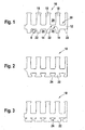
- a first embodiment of a strip-shaped blade 10 is shown in fragmentary form.
- the slat 10 has a yoke portion 12 which extends over the entire length of the slat 10.
- the yoke portion 12 has a first side 14 and a second side 16. From the first side 14, first teeth 18 extend; between the first teeth 18 are first grooves 20.
- second teeth 22 are arranged, which are integrally connected to the yoke portion 12 and the first teeth 18. Between the second teeth 22 are second grooves 24.
- an axis can be determined, which extends in Figure 1 from left to right through the yoke portion 12.
- first teeth 18 and second teeth 22 it can be stated in connection with this axis that the second teeth 22 are arranged at a position of the first teeth 18.
- the strip-like lamella 10 is intended, like all other exemplary embodiments, for the lamellae 10 to be formed from the elongated with respect to the yoke portion first of the straight state into a round shape, so that a total of an annular arrangement of each individual originally straight strip-shaped lamella 10th results.
- Each strip-shaped lamella 10 is bent with further lamellae arranged in a stack in such a way that the first teeth 18 extend to a radial inner side of a finished stand or a round, curved strip-shaped lamella.
- the second teeth 22 then point radially outward.
- the first grooves 20 and also the second grooves 24 are each formed slightly trapezoidal, wherein the shorter parallel side of an assumed trapezoid represents the radial outer side of the yoke portion 12.
- the corners of the first grooves 20, that is, the transitions from the second teeth 22 to the second side of the yoke portion 12 are rounded.
- the first grooves 20 and the second grooves 24 each have the same groove contour starting from the first side 14 or second side 16 of the yoke region 12, wherein the first groove 20 is larger and follows the length starting from a length, which corresponds to the second groove 24, of course, deviates from the second groove contour.
- the indicated half second tooth 22 is optional.
- the blade 10 is with a different outer contour, d. H. provided with other second teeth 22.
- the strip-shaped lamella 10 according to the exemplary embodiment according to FIG. 2 behaves exactly like the one shown in FIG.
- the difference between the two embodiments lies in the fact that the second teeth 22 of the second embodiment have a larger surface in the axial direction, ie. H. as in the illustration according to FIG.
- a clamping force acting in the axial direction on the stator mounted in a generator housing thus acts on the enlarged second teeth 22. It can thus be increased, the clamping force or the load on the teeth 22 is lowered.
- the second groove 24 is trapezoidal in the embodiment of Figure 2.
- the exemplary embodiment according to FIG. 3 shows an embodiment of the fin 10 which is further optimized with regard to the load due to axial clamping forces, in which the second grooves 24 only have a T-shape.
- FIG. 3a A variant of the second teeth optimized with respect to the bending deformation occurring on the outside of the yoke region 12 during the round bending of the flat package is shown in FIG. 3a.
- the second teeth 22 depicted there have a notch 25 approximately in their middle, so that the second teeth 22 deform only slightly, and thus the rigidity of the flat package for axial tensioning of the stator in the housing is largely retained.
- the second grooves 24 have a generally round shape.
- These generally round shapes include both an oval shape and a circular or semicircular shape, as shown in FIG.
- first grooves 20 and second grooves 24 on the yoke region 12 are initially two dimensions of interest.
- the first dimension b 1 represents the width of the first groove 20 that results from being theoretically extended in the tooth flanks of the first groove 20 until they intersect the first side 14 or its mental extension.
- the measure between these two Intersections is the output size.
- the second measure in the first grooves 20 is the dimension b 2 that corresponds to the pure straight portion of the groove bottom of a groove 20. It is envisaged that a groove bottom 26 between each two first teeth 18 initially extends substantially straight. Furthermore, it is provided that the groove base 26 runs between at least two first teeth 18 to at least 50% straight. The minimum value of 50% corresponds to a ratio of b 2 to b 1 .
- the width b 3 is determined analogously to the width b 1 ; the width b 4 is determined analogously to the width b 2 .
- the ratio between b 4 and b 3 is favorably such that the groove bottom 28 extends between each two second teeth 22 at least 65% straight.
- a favorable value for the ratio between b 2 and b 1 has resulted in about 65%.
- An analogous favorable ratio between b 4 and b 3 is between 60% and 85%, or better between 60% and 75%. The best showed the range between 63% and 71%.
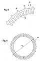
- FIG. 6 shows a detail of a stand 30 made up of lamellas 10 according to the exemplary embodiment according to FIG.
- the stator 30 has on its outer periphery second teeth 22 which transmit the corresponding axial force in known axial clamping technology.
- a stand 30 is also shown.
- These lamellae 10 also serve to absorb axial forces, but these lamellae 10 serve to realize the known in itself center lamella clamping technology.
- lamellae are without second teeth 22, so that their outer periphery is substantially cylindrical.
- a specific design is provided for the second teeth 22 on the radially outwardly directed side of the teeth 22 in order to obtain a very low friction between the outside of the strip-shaped stator lamination and a bending tool when bending the strip-shaped stator lamination.
- the second tooth 22 has a radius R in the size of half the diameter Da at its radially outwardly directed contour.
- the radius is smaller than the radius of the stator 30.
- a radius R of approximately 50-60% of the peripheral width of a second tooth 22 is provided for the radially outwardly directed contour, thus the radius is much smaller than the radius of the stator 30.
- a radius R decreasing continuously from the outer diameter Da is provided for the radially outwardly directed contour, this radius ultimately having a radius R of approximately 15-30% of the peripheral width of the second tooth 22 in FIG lateral tooth flanks merges.
- the outer diameter Da is greater than R1, R1 is greater than R2.
- the value range between 1.5 mm and 10 mm has resulted
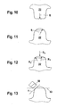
- the second teeth 22 are chamfered at their radially and axially outer corners relative to the stator, FIG. 13, or a stator fitting is turned on, d. H. is cylindrically turned off to finally simply insert the stand into an opening of the housing housing accommodating.
- Rounding on the second teeth 22 also improve the quality of painting, as resulting in significantly lower color accumulations.
- FIG. 14 shows a detail of a stator core 30, formed from the lamellae according to the invention, which has at least one end lamella with second teeth 22, which have an axial end face, which merges into the non-axial outer contour of the second teeth 22 through a rounded transition.
- This Anformung can be done, for example, by stamping on the outer lamellar strip of the flat pack, before or after packaging.
- the rounding is preferably arranged on the radially outwardly directed side of the external teeth but also on the peripheral sides of the teeth. To that the contour of the first teeth 18 is rounded, so that damage to inserted windings - especially during the round bending of the stator core with the inserted winding - can be avoided.
- FIG. 15 shows an electric machine 40 which carries a stator 30 or a stator core from the lamellae 10 according to the invention.
- stator lamination stack formed from the lamellae 10 according to the invention is provided in front of the round bending with a stator winding whose coil sides are completely in the first grooves 20 before the round bending.
- the arrangement of the coil sides depends on the winding design.
Claims (9)
- Lame en forme de bande pour un stator (30) d'une machine électrique (40), ayant une zone en forme de culasse (12) et plusieurs premières dents (18) reliées en une pièce, d'un premier côté (14), à la zone en forme de culasse (12), ainsi que des premières rainures (20) disposées entre ces dents, et des secondes dents (22) reliées en une pièce avec la zone en forme de culasse (12) d'un deuxième côté (16) situé face au premier côté (14), disposées à une position des premières dents (18), ainsi que des secondes rainures (24) disposées entre ces dents, ayant une largeur b4 qui correspond à une partie purement rectiligne au fond de la rainure (28) et une largeur b3 qui est une mesure entre deux points d'intersection, et, pour déterminer les points d'intersection, les flancs des dents de la deuxième rainure (24) sont prolongés théoriquement et les prolongements imaginaires coupent le fond de la rainure (28), le rapport entre les largeurs b4 et b3 étant de 60 % à 85 %.
- Lame en forme de bande selon la revendication 1,
caractérisée en ce qu'
un fond de rainure (26) s'étend de façon sensiblement rectiligne entre chacune des deux premières dents (18). - Lame en forme de bande selon la revendication 2,
caractérisée en ce que
le fond de rainure (26) s'étend de façon rectiligne à au moins 50 % entre chacune des deux premières dents (18). - Lame en forme de bande selon l'une des revendications précédentes,
caractérisée en ce que
le fond de rainure (26) s'étend de façon rectiligne à au moins 65 % entre chacune des deux secondes dents (22). - Lame en forme de bande selon l'une des revendications précédentes,
caractérisée en ce que
la seconde rainure (24) est trapézoïdale ou en forme de T. - Lame en forme de bande selon l'une des revendications précédentes,
caractérisée en ce qu'
une face des secondes dents (22), dirigée vers l'extérieur, présente un rayon inférieur à celui du stator (30). - Empilage de tôles de stator destiné à une machine électrique,
caractérisé en ce qu'
il est fabriqué en partie à partir de lames (10) selon l'une des revendications précédentes. - Empilage de tôles de stator selon la revendication précédente,
caractérisé en ce qu'
il présente une lame d'extrémité ayant des secondes dents (22) qui présentent une face frontale axiale, celle-ci se transformant, par une transition arrondie, en contour extérieur non axial des secondes dents (22). - Machine électrique avec un empilage de tôles de stator selon la revendication 7 ou 8.
Applications Claiming Priority (3)
| Application Number | Priority Date | Filing Date | Title |
|---|---|---|---|
| DE10243979 | 2002-09-20 | ||
| DE10243979 | 2002-09-20 | ||
| PCT/DE2003/003154 WO2004030185A1 (fr) | 2002-09-20 | 2003-09-22 | Lame en forme de bande et empilage de toles de stator pour une machine electrique |
Publications (2)
| Publication Number | Publication Date |
|---|---|
| EP1543604A1 EP1543604A1 (fr) | 2005-06-22 |
| EP1543604B1 true EP1543604B1 (fr) | 2006-11-29 |
Family
ID=32038172
Family Applications (1)
| Application Number | Title | Priority Date | Filing Date |
|---|---|---|---|
| EP03798074A Expired - Lifetime EP1543604B1 (fr) | 2002-09-20 | 2003-09-22 | Lame en forme de bande et empilage de toles de stator pour une machine electrique |
Country Status (4)
| Country | Link |
|---|---|
| US (1) | US7129614B2 (fr) |
| EP (1) | EP1543604B1 (fr) |
| DE (2) | DE50305865D1 (fr) |
| WO (1) | WO2004030185A1 (fr) |
Families Citing this family (15)
| Publication number | Priority date | Publication date | Assignee | Title |
|---|---|---|---|---|
| US7262540B2 (en) * | 2004-02-26 | 2007-08-28 | Lg Electronics Inc. | Stator of outer rotor type motor for drum type washing machine |
| US20050279274A1 (en) * | 2004-04-30 | 2005-12-22 | Chunming Niu | Systems and methods for nanowire growth and manufacturing |
| JP4640008B2 (ja) | 2005-07-15 | 2011-03-02 | 株式会社デンソー | 車両用回転電機 |
| KR100808194B1 (ko) | 2006-05-19 | 2008-02-29 | 엘지전자 주식회사 | 아우터 로터 타입 모터의 스테이터 |
| KR20080000172A (ko) * | 2006-06-26 | 2008-01-02 | 엘지전자 주식회사 | 스테이터 코어 |
| KR101154994B1 (ko) * | 2006-06-26 | 2012-06-14 | 엘지전자 주식회사 | 스테이터 코어 |
| DE102006034109A1 (de) | 2006-07-24 | 2008-01-31 | Robert Bosch Gmbh | Radiale Zentrierfläche eines Ständekerns |
| JP4523609B2 (ja) | 2007-01-26 | 2010-08-11 | 三菱電機株式会社 | 回転電機の固定子の製造方法 |
| US7659680B1 (en) | 2007-02-14 | 2010-02-09 | Mcvickers Jack C | Motor battery systems |
| US7576507B2 (en) * | 2007-02-14 | 2009-08-18 | Mcvickers Jack C | Motor battery systems |
| US20100101879A1 (en) * | 2007-02-14 | 2010-04-29 | Mcvickers Jack C | Motor Battery Systems |
| WO2009028066A1 (fr) * | 2007-08-30 | 2009-03-05 | Mitsubishi Electric Corporation | Alternateur pour véhicule |
| US8941282B2 (en) * | 2012-03-05 | 2015-01-27 | Siemens Energy, Inc. | Turbine generator stator core attachment technique |
| US20130293043A1 (en) * | 2012-05-04 | 2013-11-07 | General Electric Company | Electro-mechanical rotating machine spacer block |
| KR101940682B1 (ko) * | 2015-04-07 | 2019-01-22 | 엘지이노텍 주식회사 | 스테이터 및 이를 포함하는 모터 |
Family Cites Families (12)
| Publication number | Priority date | Publication date | Assignee | Title |
|---|---|---|---|---|
| US3886256A (en) * | 1971-07-30 | 1975-05-27 | Hitachi Ltd | Stator core for rotary electric machines and method of manufacturing the same |
| US4102040A (en) * | 1975-07-03 | 1978-07-25 | Societe Anonyme Pour L'equipement Electrique Des Vehicules S.E.V. Marchal | Method of manufacturing a curved component of a magnetic circuit |
| JPS58212336A (ja) * | 1982-05-31 | 1983-12-10 | Matsushita Electric Ind Co Ltd | 回転電機の固定子鉄心 |
| JPS5963940A (ja) * | 1982-10-05 | 1984-04-11 | Matsushita Electric Ind Co Ltd | 軸方向空隙形回転電機の巻鉄心 |
| JPS6051426A (ja) * | 1983-08-26 | 1985-03-22 | Matsushita Electric Ind Co Ltd | 軸方向空隙誘導電動機 |
| US4712292A (en) * | 1984-10-12 | 1987-12-15 | General Electric Company | Method of assembling a stationary assembly for a dynamoelectric machine |
| JP2834988B2 (ja) * | 1993-09-14 | 1998-12-14 | 株式会社三協精機製作所 | 回転電機の積層コアの製造方法 |
| JP3508445B2 (ja) * | 1997-02-12 | 2004-03-22 | 株式会社デンソー | ヘリカルステータコア |
| JP3359863B2 (ja) * | 1998-04-08 | 2002-12-24 | 三菱電機株式会社 | 固定子鉄芯の製造方法 |
| JP3716808B2 (ja) * | 2002-04-01 | 2005-11-16 | 日産自動車株式会社 | 回転電機 |
| DE10243985A1 (de) * | 2002-09-20 | 2004-04-01 | Robert Bosch Gmbh | Ständerblechpaket |
| JP4042612B2 (ja) * | 2003-04-11 | 2008-02-06 | 株式会社デンソー | 回転電機の回転子およびその製造方法 |
-
2003
- 2003-09-22 US US10/527,918 patent/US7129614B2/en not_active Expired - Lifetime
- 2003-09-22 DE DE50305865T patent/DE50305865D1/de not_active Expired - Lifetime
- 2003-09-22 EP EP03798074A patent/EP1543604B1/fr not_active Expired - Lifetime
- 2003-09-22 WO PCT/DE2003/003154 patent/WO2004030185A1/fr active IP Right Grant
- 2003-09-22 DE DE10344221A patent/DE10344221A1/de not_active Withdrawn
Also Published As
| Publication number | Publication date |
|---|---|
| DE10344221A1 (de) | 2004-05-06 |
| DE50305865D1 (de) | 2007-01-11 |
| US7129614B2 (en) | 2006-10-31 |
| EP1543604A1 (fr) | 2005-06-22 |
| WO2004030185A1 (fr) | 2004-04-08 |
| US20060125339A1 (en) | 2006-06-15 |
Similar Documents
| Publication | Publication Date | Title |
|---|---|---|
| EP1543604B1 (fr) | Lame en forme de bande et empilage de toles de stator pour une machine electrique | |
| DE102004015849B4 (de) | Anker einer rotierenden elektrischen Maschine | |
| EP1702395B1 (fr) | Procede de fabrication d'un stator et stator ainsi fabrique | |
| DE4138829C2 (de) | Kommutator für einen Motor und Verfahren zu dessen Herstellung | |
| AT505066B1 (de) | Verfahren zum maschinellen wickeln einer spule | |
| DE112013007053T5 (de) | Eisenkern-Element, Stator vom Innenrotortyp für eine elektrische Rotationsmaschine sowie Herstellungsverfahren für einen Stator vom Innenrotortyp für eine elektrische Rotationsmaschine | |
| DE3008454A1 (de) | Laeufer fuer umlaufende maschinen und herstellungsverfahren dafuer | |
| WO2004032307A1 (fr) | Stator pour une machine electrique | |
| DE102013215812A1 (de) | Elektrische Maschine | |
| EP1702396B1 (fr) | Stator de machine electrique | |
| DE112017006320T5 (de) | Statorkern für eine elektrische rotationsmaschine und zugehöriges herstellungsverfahren | |
| CH648705A5 (de) | Staenderanordnung mit luftspaltwicklung fuer elektrische maschinen grosser leistung. | |
| EP1883149B1 (fr) | Surface de centrage radial d'une carcasse statorique | |
| WO2019171218A1 (fr) | Unité rotor et moteur électrique | |
| DE4206434C2 (de) | Miniaturmotor mit einem zusammengebauten Kommutator | |
| DE19543998B4 (de) | Verfahren zum Herstellen eines Kommutatorringes für einen Kommutator | |
| WO2007000219A1 (fr) | Ebauche de conducteur pour un commutateur a tambour, procede de fabrication de ladite ebauche et commutateur a tambour ainsi obtenu | |
| DE102010043976A1 (de) | Komponente zum Herstellen einer Maschinenkomponente für eine elektrische Maschine | |
| EP1508953B1 (fr) | Elément principal d'une machine électrique | |
| DE102004045659A1 (de) | Vorrichtung und Verfahren zur Herstellung eines Stators einer elektrischen Maschine | |
| WO2012089404A2 (fr) | Dent d'enroulement pour une machine électrique, composants de machine et machine électrique | |
| DE102017100891A1 (de) | Motorständer und Verfahren zum Bilden des Motorständers | |
| DE102016116184A1 (de) | Einphasiger Permanentmagnetmotor und Ständerkern davon | |
| AT525718B1 (de) | Rotor | |
| EP1527507B1 (fr) | Segment en bande et paquet de toles statorique pour une machine electrique |
Legal Events
| Date | Code | Title | Description |
|---|---|---|---|
| PUAI | Public reference made under article 153(3) epc to a published international application that has entered the european phase |
Free format text: ORIGINAL CODE: 0009012 |
|
| 17P | Request for examination filed |
Effective date: 20050420 |
|
| AK | Designated contracting states |
Kind code of ref document: A1 Designated state(s): AT BE BG CH CY CZ DE DK EE ES FI FR GB GR HU IE IT LI LU MC NL PT RO SE SI SK TR |
|
| RBV | Designated contracting states (corrected) |
Designated state(s): DE FR IT |
|
| GRAP | Despatch of communication of intention to grant a patent |
Free format text: ORIGINAL CODE: EPIDOSNIGR1 |
|
| GRAC | Information related to communication of intention to grant a patent modified |
Free format text: ORIGINAL CODE: EPIDOSCIGR1 |
|
| GRAS | Grant fee paid |
Free format text: ORIGINAL CODE: EPIDOSNIGR3 |
|
| GRAA | (expected) grant |
Free format text: ORIGINAL CODE: 0009210 |
|
| AK | Designated contracting states |
Kind code of ref document: B1 Designated state(s): DE FR IT |
|
| REF | Corresponds to: |
Ref document number: 50305865 Country of ref document: DE Date of ref document: 20070111 Kind code of ref document: P |
|
| ET | Fr: translation filed | ||
| PLBE | No opposition filed within time limit |
Free format text: ORIGINAL CODE: 0009261 |
|
| STAA | Information on the status of an ep patent application or granted ep patent |
Free format text: STATUS: NO OPPOSITION FILED WITHIN TIME LIMIT |
|
| 26N | No opposition filed |
Effective date: 20070830 |
|
| REG | Reference to a national code |
Ref country code: FR Ref legal event code: PLFP Year of fee payment: 14 |
|
| REG | Reference to a national code |
Ref country code: FR Ref legal event code: PLFP Year of fee payment: 15 |
|
| REG | Reference to a national code |
Ref country code: DE Ref legal event code: R081 Ref document number: 50305865 Country of ref document: DE Owner name: SEG AUTOMOTIVE GERMANY GMBH, DE Free format text: FORMER OWNER: ROBERT BOSCH GMBH, 70469 STUTTGART, DE |
|
| REG | Reference to a national code |
Ref country code: FR Ref legal event code: TP Owner name: SEG AUTOMOTIVE GERMANY GMBH, DE Effective date: 20180315 |
|
| REG | Reference to a national code |
Ref country code: FR Ref legal event code: PLFP Year of fee payment: 16 |
|
| PGFP | Annual fee paid to national office [announced via postgrant information from national office to epo] |
Ref country code: DE Payment date: 20190919 Year of fee payment: 17 Ref country code: IT Payment date: 20190923 Year of fee payment: 17 Ref country code: FR Payment date: 20190918 Year of fee payment: 17 |
|
| REG | Reference to a national code |
Ref country code: DE Ref legal event code: R119 Ref document number: 50305865 Country of ref document: DE |
|
| PG25 | Lapsed in a contracting state [announced via postgrant information from national office to epo] |
Ref country code: DE Free format text: LAPSE BECAUSE OF NON-PAYMENT OF DUE FEES Effective date: 20210401 Ref country code: FR Free format text: LAPSE BECAUSE OF NON-PAYMENT OF DUE FEES Effective date: 20200930 |
|
| PG25 | Lapsed in a contracting state [announced via postgrant information from national office to epo] |
Ref country code: IT Free format text: LAPSE BECAUSE OF NON-PAYMENT OF DUE FEES Effective date: 20200922 |