EP1542750B1 - Inhalator - Google Patents
Inhalator Download PDFInfo
- Publication number
- EP1542750B1 EP1542750B1 EP03748325A EP03748325A EP1542750B1 EP 1542750 B1 EP1542750 B1 EP 1542750B1 EP 03748325 A EP03748325 A EP 03748325A EP 03748325 A EP03748325 A EP 03748325A EP 1542750 B1 EP1542750 B1 EP 1542750B1
- Authority
- EP
- European Patent Office
- Prior art keywords
- indicator member
- inhaler
- wheel
- air channel
- channel assembly
- Prior art date
- Legal status (The legal status is an assumption and is not a legal conclusion. Google has not performed a legal analysis and makes no representation as to the accuracy of the status listed.)
- Expired - Lifetime
Links
Images


Classifications
-
- A—HUMAN NECESSITIES
- A61—MEDICAL OR VETERINARY SCIENCE; HYGIENE
- A61M—DEVICES FOR INTRODUCING MEDIA INTO, OR ONTO, THE BODY; DEVICES FOR TRANSDUCING BODY MEDIA OR FOR TAKING MEDIA FROM THE BODY; DEVICES FOR PRODUCING OR ENDING SLEEP OR STUPOR
- A61M15/00—Inhalators
-
- A—HUMAN NECESSITIES
- A61—MEDICAL OR VETERINARY SCIENCE; HYGIENE
- A61M—DEVICES FOR INTRODUCING MEDIA INTO, OR ONTO, THE BODY; DEVICES FOR TRANSDUCING BODY MEDIA OR FOR TAKING MEDIA FROM THE BODY; DEVICES FOR PRODUCING OR ENDING SLEEP OR STUPOR
- A61M15/00—Inhalators
- A61M15/0065—Inhalators with dosage or measuring devices
- A61M15/0068—Indicating or counting the number of dispensed doses or of remaining doses
- A61M15/007—Mechanical counters
- A61M15/0071—Mechanical counters having a display or indicator
- A61M15/0073—Mechanical counters having a display or indicator on a ring
-
- G—PHYSICS
- G06—COMPUTING; CALCULATING OR COUNTING
- G06M—COUNTING MECHANISMS; COUNTING OF OBJECTS NOT OTHERWISE PROVIDED FOR
- G06M1/00—Design features of general application
- G06M1/04—Design features of general application for driving the stage of lowest order
- G06M1/041—Design features of general application for driving the stage of lowest order for drum-type indicating means
-
- G—PHYSICS
- G06—COMPUTING; CALCULATING OR COUNTING
- G06M—COUNTING MECHANISMS; COUNTING OF OBJECTS NOT OTHERWISE PROVIDED FOR
- G06M1/00—Design features of general application
- G06M1/14—Design features of general application for transferring a condition from one stage to a higher stage
- G06M1/16—Design features of general application for transferring a condition from one stage to a higher stage self-operating, e.g. by Geneva mechanism
- G06M1/163—Design features of general application for transferring a condition from one stage to a higher stage self-operating, e.g. by Geneva mechanism with drums
-
- G—PHYSICS
- G06—COMPUTING; CALCULATING OR COUNTING
- G06M—COUNTING MECHANISMS; COUNTING OF OBJECTS NOT OTHERWISE PROVIDED FOR
- G06M1/00—Design features of general application
- G06M1/22—Design features of general application for visual indication of the result of count on counting mechanisms, e.g. by window with magnifying lens
- G06M1/24—Drums; Dials; Pointers
- G06M1/241—Drums
-
- A—HUMAN NECESSITIES
- A61—MEDICAL OR VETERINARY SCIENCE; HYGIENE
- A61M—DEVICES FOR INTRODUCING MEDIA INTO, OR ONTO, THE BODY; DEVICES FOR TRANSDUCING BODY MEDIA OR FOR TAKING MEDIA FROM THE BODY; DEVICES FOR PRODUCING OR ENDING SLEEP OR STUPOR
- A61M2202/00—Special media to be introduced, removed or treated
- A61M2202/06—Solids
- A61M2202/064—Powder
Definitions
- This invention concerns dry powder inhalers for the delivery of metered doses of medicament, and counters associated with the inhalers for counting and displaying the number of doses administered or remaining within the inhaler.
- PMDIs pressurized metered dose inhalers
- DPIs dry powder inhalers
- US 6,182,655 and US 6,076,521 disclose different types of multidose dry powder inhaler.
- DPIs can be used for oral and nasal administration and may be presented with the drug formulation pre-metered as capsules (unit-dose inhaler), blisters and cartridges (multi-unit dose inhaler) or as bulk material in a reservoir (multi-dose inhalers).
- a necessary design feature of PMDIs and multi-dose DPIs is that they contain more formulation than strictly required to expel the labeled number of actuations/doses.
- a potential problem which may be particularly acute for PMDIs is dose inconsistency beyond the labeled number of actuations/doses.
- a patient unknowingly using a PMDI or multi-dose DPI beyond the recommended number of doses may risk not receiving the correct drug dose with possibly dangerous consequences.
- a counter integrally with the inhaler to count and display to the user the number of doses remaining within the inhaler. This will allow the user sufficient warning as to when the inhaler is running low and should, therefore, be replaced so as to avoid the potential for sub-therapeutic dose administration.
- the counter should be simple in design, reliable in operation and easy to read and interpret.
- the invention concerns a dry powder inhaler for administering a metered dose of a medicament to a user.
- the inhaler comprises a reservoir holding the medicament and an air channel assembly engaged with and movable relatively to the reservoir for receiving the dose of medicament upon the relative motion.
- the medicament is administered when the user draws a breath through the air channel assembly; the medicament, in powdered form, being entrained in the air drawn through the air channel assembly and into the user's air passageways.
- the inhaler also comprises a counter for counting the number of doses dispensed from the reservoir or the number of doses that can still be delivered before the device is considered empty.
- the counter comprises a first indicator member which moves one increment in response to the motion of the air channel assembly relative to the reservoir. The increment of movement corresponds to each dose dispensed from the reservoir.
- the counter also has a second indicator member which moves intermittently in response to motion of the first indicator member. Both indicator members have indicia thereon for displaying the number of doses dispensed from the reservoir or the number of doses that can still be delivered before the device is considered empty.
- a rotatory intermittent drive transfer mechanism is positioned between, and engaged with, the first and second indicator members.
- the first indicator member drives the rotatory intermittent drive transfer mechanism and the rotatory intermittent drive transfer mechanism drives the second indicator member intermittently upon motion of the first indicator member.
- the first indicator member is a unit wheel.
- the second indicator member moves one increment for every ten increments of the unit wheel (hereinafter a "tens" wheel), and the indicia thereon represent tens of doses, whereas the indicia on the unit wheel represent unit doses.
- the inhaler comprise a third, and optionally fourth, indicator member.
- the third indicator member can move one increment for every 100 increments of the tens wheel (hereinafter a "hundreds" wheel), and the indicia thereon represent hundreds of doses.
- the fourth indicator member can move one increment for every 1000 increments of the hundreds wheel (hereinafter a "thousands" wheel), and the indicia thereon represent thousands of doses.
- the reservoir is arranged circumferentially around a central axis and the air channel assembly is positioned coaxially with the reservoir and rotatably movable about the central axis relatively thereto.
- the first and second indicator members are also preferably positioned coaxially with the reservoir and rotatably movable about the central axis for counting the doses dispensed from the reservoir or the number of doses that can still be delivered before the device is considered empty.
- the unit wheel has a first surface on which the counting indicia representing unit doses appear, the first surface facing radially outwardly from the central axis.
- the tens wheel has a second surface on which the indicia representing tens of doses appear, the second surface being transparent and facing radially outwardly from the central axis.
- the unit wheel is preferably nested within the tens wheel and the indicia on the unit wheel juxtapose with the indicia on the tens wheel and are visible through the transparent surface of the tens wheel to display the number of the doses dispensed from the reservoir or the number of doses that can still be delivered before the device is considered empty.
- the unit and tens wheels are connected by a rotatory intermittent drive transfer mechanism which imparts intermittent motion to the tens wheel upon motion of the unit wheel.
- the rotatory intermittent drive transfer mechanism comprises a slave wheel rotatable about an offset axis offset from the central axis and substantially parallel thereto.
- the slave wheel has a drive transfer wheel on one face and a gear on the opposite face.
- the unit wheel has a foot extending therefrom for engaging the drive transfer wheel, and the tens wheel has gear teeth arranged around its interior surface circumference for meshing with the gear on the opposite face of the slave wheel.
- the foot on the unit wheel engages with the drive transfer wheel and causes the slave wheel to rotate, whereupon the gear teeth on the slave wheel engage and rotate the tens wheel one increment.
- the gear and drive transfer wheel are situated in the interior circumference, so that the drive transfer mechanism is able to drive the unit and tens wheel in the same direction.
- the drive transfer mechanism is able to drive the unit and tens wheel in the opposite direction to each other.
- the gear ratio the total number of doses that can be displayed by the counter can also be changed.
- the slave wheel may incrementally rotate the tens wheel intermittently in response to rotation of the unit wheel in accordance with the following preferred embodiment.
- the unit wheel has an inwardly facing circumferential surface with a notch therein.
- the foot which extends from the unit wheel, is positioned adjacent to the notch.
- the drive transfer wheel positioned on a face of the slave wheel facing the unit wheel, has a plurality of receptacles spaced circumferentially therearound, each for receiving the foot on the unit wheel.
- a rotation-preventing feature is embodied in a plurality of outwardly extending lobes positioned between the drive transfer wheel and the gear on the slave wheel.
- Each of the lobes is aligned with a respective receptacle on the drive transfer wheel, one or more of the lobes engaging the inner circumferential surface of the unit wheel as the unit wheel rotates, thereby preventing inadvertent rotation of the slave wheel and, thus, the tens wheel.
- One lobe of the slave wheel is received within the notch in the inner circumferential surface of the unit wheel when the foot of the unit wheel engages one of the receptacles on the drive transfer wheel aligned with the lobe to rotate the slave wheel.
- the notch provides clearance between the lobe and the inner circumferential surface of the unit wheel, allowing the slave wheel to incrementally rotate, thereby rotating the tens wheel.
- Another of the lobes then engages the inner circumferential surface of the unit wheel upon incremental rotation of the slave wheel, thereby again preventing rotation of the slave wheel until the foot on the unit wheel again engages the next one of the receptacles, aligned with the next lobe, on the drive transfer wheel.
- a first indicator member e.g. a unit wheel
- a second indicator member e.g. a tens wheel
- first indicator member e.g. a unit wheel
- second indicator member e.g. a tens wheel
- It is again another object of the invention to provide a rotatory intermittent drive transfer mechanism comprising a slave wheel with a drive transfer wheel on one face and a gear on the opposite face.
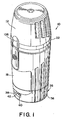
- FIG 1 is a perspective view of a preferred embodiment of an inhaler 10 according to the invention.
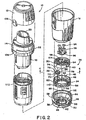
- Figure 2 is an exploded view of the inhaler 10 shown in Figure 1 .
- the inhaler comprises a dust cap 12, an air channel assembly 14, a medicament reservoir 16 for holding a powdered medicament (not shown) and a barrel 18.
- the air channel assembly 14 comprises a mouthpiece 20, a collar 22, a reservoir 16, and a drive sub-assembly 112.
- Drive sub-assembly 112 fits coaxially within barrel 18, and the reservoir 16 of air channel assembly 14 fits coaxially within the drive sub-assembly 112.
- Collar 22 and mouthpiece 20 on the end of the air channel assembly 14 extend outwardly from the reservoir 16 and barrel 18 to engage the lips of a user as described below.
- a counter 26 is mounted onto the inhaler 10 on the end of barrel 18 opposite the dust cap 12.
- Counter 26 comprises a coupling 28, a unit wheel 30, a slave wheel 32, a tens wheel 34 and a cover 36 in which the unit wheel 30, slave wheel 32 and tens wheel 34 are rotatably mounted.
- Cover 36 has a window 38 therein through which indicia 40 and 42, printed on the unit and tens wheels respectively, may be viewed, indicating the number of doses that can still be delivered before the medicament reservoir 16 is considered empty or the number of doses dispensed therefrom.
- cover 36 of counter 26 has a bottom 44 which supports the tens wheel 34 for rotational motion about a central axis 46.
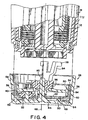
- Tens wheel 34 has an inwardly extending flange 48 which is sized to surround and engage a raised boss 50 positioned on the bottom 44 concentric with the central axis 46 (see also Figures 4 and 4A ).
- Cooperation between the flange 48 and the boss 50 keeps the tens wheel 34 concentric within the cover 36 and allows guided rotation of the tens wheel about the central axis 46.
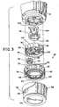
- Bottom 44 also has a circular groove 52 positioned concentric with the central axis. The groove 52 is sized to accept a tab 54, best shown in Figure 3 .
- the tab 54 extends downwardly from the tens wheel 34 and tracks within the groove 52 as the tens wheel rotates about central axis 46. As shown in Figure 2 , a stop block 56 is positioned within the groove 52. When the tens wheel 34 has rotated such that the last of the series of indicia has been displayed in the window 38, the stop block 56 engages the tab 54 to halt its rotation and thereby preventing the counter from resetting itself after it has counted down to zero and thus give a false reading of the number of doses remaining in the inhaler. Also, when incrementing the counter it is foreseeable that the stop block's 56 ability to engage the tab 54 to halt its rotation would also prevent the counter from resetting itself when the last of the series of indicia has been displayed in the window 38.
- an outwardly facing sidewall 58 on the cover 36 extends circumferentially around the bottom 44 and is attached to the end of barrel 18 to enclose the counter 26.
- the cover 36 is mounted onto the barrel 18 by means of a snap fit (not shown).
- Window 38 is positioned in sidewall 58, allowing viewing of indicia 40 and 42.
- Indicia 42 are positioned on a radially outwardly facing side surface 60 extending circumferentially around the tens wheel 34.
- the indicia 42 can be positioned on the radially inwardly facing side surface extending circumferentially around the tens wheel 34.
- Side surface 60 is positioned concentric with central axis 46 and is adjacent to sidewall 58.
- Indicia 42 thereon are positioned so as to align with and be visible through the window 38 as the tens wheel rotates within the cover 36.
- the tens wheel 34 is a decimal wheel showing tens of doses that can still be delivered before the device is considered empty, and thus, the indicia 42 thereon are positioned and spaced apart on the side surface 60 to align to the left side of the window 38, leaving room in the window for indicia 40 on the unit wheel 30 to be displayed through window 38 to the right of the indicia 42 on the tens wheel 34 to properly indicate the unit number of doses that can still be delivered before the device is considered empty.
- a set of inwardly facing gear teeth 62 are positioned circumferentially around the tens wheel 34 above the flange 48. Gear teeth 62 allow the tens wheel 34 to move only when driven by the device and thus prevents freewheeling of the tens wheel 34.
- slave wheel 32 is mounted on an offset axle 66 extending upwardly from the bottom 44 of the cover 36. Axle 66 is offset from the central axis 46 and thereby provides an offset axis of rotation 68 about which the slave wheel 32 rotates.
- a gear 70 is positioned on one face 72 of the slave wheel 32, the gear 70 meshing with the gear teeth 62 on the tens wheel 34 such that rotation of the slave wheel 32 about the offset axis 68 drives the tens wheel 34 in rotation about the central axis 46 (see also Figure 8 ).
- a geneva wheel 74 is positioned on the opposite face 76 of the slave wheel 32.
- the geneva wheel 74 has a plurality of receptacles 78, four being shown by way of example. The receptacles 78 are positioned in spaced relation circumferentially around the geneva wheel.
- Each receptacle is sized and positioned to receive a foot 80 extending downwardly from the unit wheel (see also Figure 3 ).
- the foot 80 engages one of the receptacles 78 once on each complete revolution of the unit wheel 30, and rotates the geneva wheel 74 about the offset axis 68.
- the geneva wheel 74 has four receptacles 78, the geneva wheel rotates through an angle of about 90° about the offset axis 68.
- rotation of the geneva wheel 74 causes a corresponding rotation of the gear 70 (since both the geneva wheel 74 and the gear 70 are on opposite faces of the slave wheel 32) which drives the tens wheel 34 in rotation about central axis 46.
- the geometry and positioning of the geneva wheel 74, gear 70 and the indicia 42 on the tens wheel 34 are such that rotation of the slave wheel 32 positions the next indicia 42 visible within the window 38.
- unit wheel 30 is rotatably mounted on a central axle 82 substantially aligned with the central axis 46 and extending from the bottom 44 of the cover 36.
- Unit wheel 30 comprises a radially outwardly facing side surface 84 extending circumferentially around and upon which the unit indicia 40 are positioned.
- the unit wheel may comprise a transparent radial side surface 84 extending circumferentially around, upon which the unit indicia may be positioned on the inward face of said surface so as to still be readable from the outwardly facing surface.
- the unit wheel 30 is nested within the tens wheel 34 such that the outwardly facing side surfaces 60 and 84 are coaxial with and adjacent to one another.
- the side surface 60 on the tens wheel 34 is transparent, thus, allowing the indicia 40 on the unit wheel behind it to be visible, together with the indicia on the tens wheel 34, through the window 38.
- the unit indicia 40 are positioned and spaced around side surface 84 so as to align to the right side of the window 38.
- the tens indicia 42 on the tens wheel 34 and the unit indicia 40 on the unit wheel 30 are visible together in the window 38 to show the number of doses that can still be delivered before the device is considered empty or doses already dispensed from the medicament reservoir 16.
- Positioning the foot 80 on the unit wheel 30 and the gear teeth 62 on the tens wheel 34 is the preferred configuration, although other configurations, for example, having two or more feet on the unit wheel, altering the ratio of the size of the slave wheel to the master wheel and having a plurality of receptacles, are also feasible.
- slave wheel 32 has a plurality of lobes 86 positioned between the gear 70 and the geneva wheel 74.
- the lobes 86 extend radially outwardly and are arranged in spaced relation circumferentially about the slave wheel 32, each lobe 86 being positioned next to a corresponding receptacle 78 of the geneva wheel 74.
- Lobes 86 engage an inwardly facing circumferential surface 88 on the unit wheel 30.
- the unit wheel 30 is driven by coupling 28 which couples the motion of the air channel assembly 14 to the counter 26.
- Coupling 28 has a plurality of legs 94 which extend from the counter 26 into the barrel 18 and engage tabs 111 on the mandrel 24 (not shown) of the air channel assembly 14.
- Legs 94 are arranged in spaced relation to one another so as to provide for lost motion between the mandrel 24 (not shown) and the coupling 28.
- the lost motion allows for the large rotational motion of the air channel assembly 14 relative to the drive sub-assembly needed to actuate the inhaler, yet also provides a reduced rotational motion of the air channel assembly 14 relative to the counter 26 needed to actuate the counter.
- Legs 94 are flexible and, thus, may be resiliently bent to facilitate assembly of the counter onto the inhaler by allowing the legs to flex and be inserted into barrel 18.
- ratchet 96 which engages pawls 98 on the unit wheel 30 (see also Figure 5 ).
- motion of the air channel assembly 14 relative to the barrel 18 as the inhaler is actuated is transmitted from the mandrel 24 (not shown) to the unit wheel 30 by means of the legs 94, the ratchet 96 and the pawls 98 on the unit wheel 30.
- the ratchet and pawl are used to move the unit wheel only in one direction to decrement (or increment) the counter for each actuation.
- actuation of the inhaler 10 requires a reciprocal motion of the air channel assembly 14 relative to the barrel 18, and the reciprocal motion must be converted to unidirectional motion of the counter 26, and this is effected by means of the ratchet 96 and pawls 98.
- the position of the ratchet 96 on the coupling 28 and pawls 98 on the unit wheel 30 are preferred for ease of manufacture but could easily be reversed and achieve the same desired effect.
- By keeping both sets of pawls 98 on the same part variations between the arms in the inhaler device is negated, thus providing a more consistent torque balance.
- a second ratchet 100 is positioned on the end of barrel 18.
- the ratchet 100 faces radially inwardly to engage pawls 102 which are mounted on the unit wheel 30 and face outwardly to engage the ratchet 100.
- Ratchet 100 and pawls 102 work in cooperation with ratchet 96 and pawls 98 to prevent retrograde motion of the unit wheel when it is actuated by the reciprocal motion of the air channel assembly 14 relative to the barrel 18.
- the cooperation of the ratchets and pawls is described in detail below in the description of counter operation. Uni-directional motion of the unit wheel is ensured by proper design of the ratchet angles and relative panel lengths of the ratchets 96 and 100 and pawls 98.
- unit wheel 30 also has a plurality of cantilevered fingers 104 which extend upwardly from the unit wheel and engage the coupling 28.
- the fingers 104 act as springs to bias the components of the counter 26 against the bottom 44 of cover 36 and the fingers 104 also bias the coupling 28 against the mandrel 24 (not shown).
- the unit wheel 30 is biased against the tens wheel 34, keeping the slave wheel 32 properly positioned and engaged with the unit and tens wheels.
- the biasing action of the fingers 104 also keeps the tens wheel 34 properly seated on the bottom 44 and the flange 48 firmly engaged with the raised boss 50 so as to generally ensure smooth operation of the counter and also help prevent powdered medicament from contaminating the counter mechanism.
- the barrel 18, cover 26, and cap 12 may be polypropylene
- the tens wheel 34 may be polycarbonate
- the slave wheel 32 may be polybutylene teraphthalate
- the unit wheel is preferably polycarbonate
- the coupling may be polybutylene terephthalate
- the air channel assembly is predominantly made of an acetal copolymer such as Hostaform ® .
- Drugs may be selected from, for example, analgesics, e.g. codeine, dihydromorphine, ergotamine, fentanyl or morphine, anginal preparations, e.g. diltiazem; antiallergics, e.g. cromoglycate, ketotifen or nedocromil; antiinfectives e.g.
- analgesics e.g. codeine, dihydromorphine, ergotamine, fentanyl or morphine
- anginal preparations e.g. diltiazem
- antiallergics e.g. cromoglycate, ketotifen or nedocromil
- antiinfectives e.g.
- cephalosporins e.g. mnethapyfilene
- antitussives e.g.
- beta-adrenergics that include bronchodilators such as ephedrine, adrenaline, fenoterol, forinoterol, isoprenaline, phenylephrine, phenylpropanolamine, reproterol, rimiterol, isoetharine, tulobuterol, orciprenaline, or (-)4-amino-3,5-dichloro-alpha.-[[[6-[2-(2-pyridinyl)ethoxy]hexyl]-amino]m ethyl]benzenemethanol, epinephrine (Primatene), formoterol (Foradil), isoproterenol (Isuprel), isoetharine (Bronkosol), metaproterenol (Alupent, Metaprel), albuterol (Proventil, Ventolin), terbutaline (Bricanyl, Brethine), bit
- anti-inflammatory drugs used in connection with the treatment of respiratory diseases include steroids such as ciclesonide beclomethasone dipropionate (Vanceril, Beclovent), budesonide (Pulmicort), dexamethasone, flunisolide (Aerobid), fluticasone (Flovent), salmeterol + fluticasone combination (Advair Diskus), and triamcinolone acetonide (Azmacort), and Mediator-release inhibitors such as cromolyn sodium (Intal), and nedocromil sodium (Tilade); leukotrine (LT) inhibitors, vasoactive intestinal peptide (VIP), tachykinin antagonists, bradykinin antagonists, endothelin antagonists,
- steroids such as ciclesonide beclomethasone dipropionate (Vanceril, Beclovent), budesonide (Pulmicort), dexamethasone, flunisolide (Aerobid), fluticasone
- intermittent drive transfer mechanism means a mechanism that intermittently transfers the drive from one element to another via a drive transfer wheel.
- An example of such a mechanism is a geneva mechanism.
- drive transfer wheel means a wheel capable of intermittently transferring a drive from one element to another.
- Examples of a drive transfer wheel include a geneva wheel, a star drive wheel or a maltese cross wheel.
- the drive transfer wheel is a geneva wheel.
- a user grasps the barrel 18 in one hand and the dust cap 12 in the other.
- the cap 12 and barrel 18 are rotated relatively to one another through an angle of about 105° about the central axis 46 with the cap 12 rotating clockwise and the barrel 18 counterclockwise when viewed from the cap end of the inhaler 10.
- Cap 12 has a tab 106 which engages a notch 108 in collar 22, causing the entire air channel assembly 14 to rotate clockwise along with the cap 12.
- the cap 12 and barrel 18 are then relatively rotated in the reverse direction through the same angle.
- the reciprocal rotation of the cap 12 and air channel assembly 14 causes a metered dose of powdered medicament to be scraped from the reservoir 16 and deposited in the air channel assembly 14.
- the user removes the cap 12, places his or her lips to the mouthpiece 20 and inhales.
- the medicament becomes entrained in an air stream drawn through the mouthpiece 20 and is drawn into the mouth, trachea and lungs of the user where it is absorbed.
- the relative rotation between the barrel 18 and the air channel assembly 14 is used to actuate the counter 26.
- a decrementing counter which counts down and indicates the number of doses that can still be delivered before the device is considered empty, is described below, it being understood that an incrementing counter, which counts upward and indicates the number of doses administered, functions in essentially the same way as the decrementing counter.
- Changing a decrementing counter to an incrementing counter is easily carried out by changing the arrangement of the printed numbers on the tens and unit wheels. References to clockwise and counterclockwise rotations which follow are defined as if viewed from the dust cap 12 of the inhaler along central axis 46.
- ratchet 96 on the coupling is rotated clockwise relatively to pawls 98 on the unit wheel, the pawls 98 slipping over the ratchet teeth 96a and clicking into place on the other side of the teeth, ready to move the unit wheel 30 upon the reverse rotation of the air channel assembly 14.
- the unit wheel 30 is prevented from rotating clockwise as the pawls 98 engage and slip over the teeth 96a by the second ratchet 100 located in barrel 18, engaged by outer pawls 102 on the unit wheel 30.
- the pawls 98 are stressed in bending only during motion of the coupling 28 relative to the unit wheel. At all other times, the pawls remain unstressed and, thus, will not take on a permanent set which could adversely affect the ratcheting action of the mechanism.
- ratchet 96 (see Figure 5 ), rotating counterclockwise, engages pawls 98 on the unit wheel 30 and rotates the unit wheel counterclockwise about the central axis 46 so that the next lower value of the indicia 40 is displayed in the window 38.
- gear 70 on the slave wheel 32 also rotates counterclockwise through 90°, its teeth engaging the gear teeth 62 on the tens wheel 34, and causing a counterclockwise rotation of the tens wheel 34 about the central axis 46 to bring the next lower indicia 42, indicating tens of doses, into view within the window 38.
- Indicia 40 on the unit wheel 30 are visible through the transparent tens wheel 34 and align with the indicia 42 on the tens wheel and together indicate the number of doses that can still be delivered before the device is considered empty.
- the gear ratio between gear 70 and the tens wheel 34 is designed to move the tens wheel in proportion to the number of divisions, indicated by the indicia 42, on the tens wheel 34. For example, a dose counter having 120 doses will require 13 divisions, corresponding to indicia from 1-12 and a blank space indicating zero, positioned on the tens wheel 34.
- the tens wheel 34 should move through an angle of about 27.7° (1/13 of a complete revolution). Note that this rotation must be achieved by a 90° rotation of the gear 70. A ratio of about 3.25 to 1 between the tens wheel 34 and the gear 70 will cause the desired rotation of the tens wheel 34. As best shown in Figure 3 , it is advantageous to provide colored indicators 110 on the tens wheel 34 positioned near the low numbered indicia 42 to provide a readily visible warning that few doses remain in the inhaler.
- a complete revolution of the tens wheel 34 is prevented by the engagement of tab 54 with the stop block 56 positioned within the circular groove 52 in the bottom 44 of cover 36 (see Figures 2 and 8 ).
- tab 54 is initially positioned adjacent to one side 56a of the stop block 56 (the position corresponding to the maximum indicia 42 being aligned within window 38) and initially moves counterclockwise away from the stop block as the tens wheel 34 rotates.
- the space on the tens wheel 34 aligned within window 38 is blank, displaying one of the colored indicators 110, and the tab 54 is engaged with the opposite side 56b of the stop block 56.
- the pawls 98 When the tens wheel 34 is prevented from turning, and upon application of sufficient torque by the user turning the cap 12, the pawls 98 will slip over the ratchet teeth 96a as the coupling 28 moves in the counterclockwise direction, thereby allowing a medicament dose to be loaded into the air channel assembly without actuating the counter 26. Normally, the pawls 98 engage the teeth 96a of ratchet 96 when the ratchet turns in the counterclockwise direction to actuate the counter 26. However, the pawls 98 are sufficiently flexible such that they will disengage from the ratchet rather than jam the entire inhaler mechanism when sufficient torque is applied and the tens wheel 34 is blocked by the stop block 56.
- the inhaler and counter according to the invention provides a compact, inexpensive and reliable means for administering measured doses of a powdered medicament, while knowing with a significant degree of precision how many doses are remaining in the inhaler at any given time and when an inhaler should be replaced with a new one.
Claims (37)
- Trockenpulverinhalator (10) zur Verabreichung einer Arzneimitteldosis, wobei der Inhalator Folgendes umfasst:ein das Arzneimittel aufnehmendes Behältnis (16);eine Luftkanalanordnung (14), die mit dem Behältnis (16) in Eingriff steht und bezüglich dessen beweglich ist, um die Arzneimitteldosis bei der Relativbewegung aufzunehmen; undeinen Zähler (26) zum Zählen einer Anzahl von Dosen, die aus dem Behältnis (16) ausgegeben wurden oder die noch zugeführt werden können, bevor der Inhalator (10) als leer betrachtet wird, wobei der Zähler (26) ein erstes Anzeigeglied (30), das sich als Reaktion auf die Relativbewegung um ein Inkrement bewegt, und ein zweites Anzeigeglied (34), das sich als Reaktion auf Bewegung des ersten Anzeigeglieds (30) intermittierend bewegt, umfasst, wobei ein Drehschrittantriebsübertragungsmechanismus (32) zwischen dem ersten und dem zweiten Anzeigeglied (30, 34) positioniert und mit ihnen in Eingriff bringbar ist, wobei das erste Anzeigeglied (30) den Drehschrittantriebsübertragungsmechanismus antreibt, wobei der Drehschrittantriebsübertragungsmechanismus das zweite Anzeigeglied (34) bei Bewegung des ersten Anzeigeglieds (30) intermittierend antreibt, wobei das erste und das zweite Anzeigeglied (30, 34) Angaben (40, 42) darauf zum Anzeigen der Anzahl der Dosen aufweisen, die aus dem Behältnis (16) ausgegeben wurden oder die noch zugeführt werden können, bevor der Inhalator (10) als leer betrachtet wird; dadurch gekennzeichnet, dass der Drehschrittantriebsübertragungsmechanismus ein Nachführrad (32) mit einem Antriebsübertragungsrad (74) auf einer Seite und einem Zahnrad (70) auf einer gegenüberliegenden Seite aufweisen, wobei das Nachführrad (32) um eine Achse drehbar ist, die von einer mittleren Achse (46) des Inhalators (10) versetzt und im Wesentlichen parallel zu ihr ist.
- Inhalator (10) nach Anspruch 1, der zur oralen Verabreichung des Arzneimittels ausgeführt ist.
- Inhalator (10) nach einem der Ansprüche 1 oder 2, wobei das Behältnis (16) umfangsmäßig um die mittlere Achse (46) angeordnet ist, wobei die Luftkanalanordnung (14) koaxial zu dem Behältnis (16) positioniert und um die mittlere Achse (46) relativ dazu drehbeweglich ist, wobei das erste Anzeigeglied (30) und das zweite Anzeigeglied (34) auch koaxial zu dem Behältnis (16) positioniert und um die mittlere Achse (46) drehbeweglich sind, um die Dosen, die aus dem Behältnis (16) ausgegeben wurden oder die noch zugeführt werden können, bevor der Inhalator (10) als leer betrachtet wird, zu zählen.
- Inhalator (10) nach einem der Ansprüche 1 bis 3, der weiterhin ein Klinkenrad (96) und eine Sperrklinke (98) zur Verbindung des ersten Anzeigeglieds (30) mit der Luftkanalanordnung (14) zum Bewegen des ersten Anzeigeglieds (30) als Reaktion auf eine Bewegung der Luftkanalanordnung (14) bezüglich des Behältnisses (16) umfasst, wobei das Klinkenrad (96) an dem ersten Anzeigeglied (30) oder an der Luftkanalanordnung (14) angebracht und um die mittlere Achse (46) damit drehbar ist, wobei die Sperrklinke (98) an dem jeweils anderen Element, dem ersten Anzeigeglied (30) oder der Luftkanalanordnung (14), angebracht ist und das Klinkenrad (96) in Eingriff nimmt, um eine Drehbewegung des ersten Anzeigeglieds (30) nur in einer Richtung um die mittlere Achse (46) zu bewirken.
- Inhalator (10) nach Anspruch 4, wobei die Sperrklinke (98) an dem ersten Anzeigeglied (30) und das Klinkenrad (96) an der Luftkanalanordnung (14) angebracht ist.
- Inhalator (10) nach Anspruch 4 oder 5, der weiterhin eine zwischen dem ersten Anzeigeglied (30) und der Luftkanalanordnung (14) positionierte Kupplung (28) umfasst, wobei ein Ende der Kupplung (28) mit dem ersten Anzeigeglied (30) zusammenwirkt und entweder das Klinkenrad (96) oder die Sperrklinke (98) umfasst, wobei das andere Ende der Kupplung (28) mehrere Schenkel (94) aufweist, die sich davon zur Ineingriffnahme der Luftkanalanordnung (14) erstrecken, wobei die Kupplung (28) eine Relativbewegung der Luftkanalanordnung (14) zum Zähler (26) zum Bewegen des ersten Anzeigeglieds (30) überträgt.
- Inhalator (10) nach Anspruch 6, wobei das Klinkenrad (96) an der Kupplung (28) und die Sperrklinke (98) an dem ersten Anzeigeglied (30) angebracht ist, wobei das Klinkenrad (96) die Sperrklinke (98) zur Drehung des ersten Anzeigeglieds (30) um die mittlere Achse (46) als Reaktion auf Bewegung der Luftkanalanordnung (14) in Eingriff nimmt.
- Inhalator (10) nach einem der Ansprüche 1 bis 7, wobei sich das erste Anzeigeglied (30) und das zweite Anzeigeglied (34) während des Betriebs in der gleichen Richtung drehen.
- Inhalator (10) nach einem der Ansprüche 1 bis 8, wobei das erste Anzeigeglied (30) eine erste Fläche aufweist, auf der die Angaben (40) erscheinen, wobei die erste Fläche von der mittleren Achse (46) radial nach außen weist, wobei das zweite Anzeigeglied (34) eine zweite Fläche aufweist, auf der die Angaben (42) erscheinen, wobei die zweite Fläche durchsichtig ist und von der mittleren Achse (46) radial nach außen weist, wobei das erste Anzeigeglied (30) in dem zweiten Anzeigeglied (34) verschachtelt ist, wobei die Angaben (40) auf dem ersten Anzeigeglied (30) auf die Angaben (42) auf dem zweiten Anzeigeglied (34) ausgerichtet und dadurch sichtbar sind, um die Anzahl der Dosen, die aus dem Behältnis (16) ausgegeben wurden oder die noch zugeführt werden können, bevor der Inhalator (10) als leer betrachtet wird, anzuzeigen.
- Inhalator (10) nach einem der Ansprüche 1 bis 9, wobei das erste Anzeigeglied (30) einen Fuß (80) aufweist, der sich zur Ineingriffnahme des Antriebsübertragungsrads (74) davon erstreckt, wobei das zweite Anzeigeglied (34) Zahnradzähne (62) aufweist, die umfangsmäßig dort herum angeordnet sind, um bei Drehung des ersten Anzeigeglieds (30) mit dem Zahnrad (70) auf der gegenüberliegenden Seite zu kämmen, wobei das erste Anzeigeglied (30) das Nachführrad (32) in Eingriff nimmt und dreht, wobei das Nachführrad (32) das zweite Anzeigeglied (34) intermittierend in Eingriff nimmt und dreht.
- Inhalator (10) nach Anspruch 10, wobei der Fuß (80) an dem ersten Anzeigeglied (30) angebracht ist und die Zahnradzähne (62) an dem zweiten Anzeigeglied (34) positioniert sind.
- Inhalator (10) nach einem der Ansprüche 1 bis 11, wobei das erste Anzeigeglied (30) ein Einheitenrad (30) umfasst und das zweite Anzeigeglied (34) ein Zehnerrad (34) umfasst, wobei sich das zweite Anzeigeglied (34) alle zehn Bewegungen des Einheitenrads (30) bewegt.
- Inhalator (10) nach einem der vorhergehenden Ansprüche, der weiterhin ein drittes und wahlweise ein viertes Anzeigeglied umfasst.
- Inhalator (10) nach einem der vorhergehenden Ansprüche, der weiterhin eine Abdeckung (36) umfasst, die an einem Ende des Inhalators (10) gegenüber der Luftkanalanordnung (14) angebracht ist, wobei die Abdeckung (36) einen Unterteil und eine nach außen weisende Seitenwand umfasst, die sich umfangsmäßig um den Unterteil herum erstreckt, wobei das zweite Anzeigeglied (34) (zum Beispiel ein Zehnerrad) einen Vorsprung (54) aufweist, der daran angebracht ist, wobei der Unterteil der Abdeckung einen Anschlagblock (56) aufweist, der zur Ineingriffnahme des Vorsprungs (54) positioniert ist und eine ganze Umdrehung des zweiten Anzeigeglieds (34) (zum Beispiel eines Zehnerrads) bezüglich der Abdeckung verhindert.
- Inhalator (10) nach Anspruch 1, wobei der Zähler (26) eine Kupplung umfasst, die die Luftkanalanordnung (14) und das erste Anzeigeglied (30) in Eingriff nimmt, wobei das erste Anzeigeglied (30) ein Einheitenrad (30) umfasst,
wobei die Kupplung das Einheitenrad (30) bei Drehung der Luftkanalanordnung (14) in Drehung versetzt, wobei das zweite Anzeigeglied (34) ein Zehnerrad umfasst, das sich als Reaktion auf eine Bewegung des Einheitenrads (30) intermittierend dreht, wobei eines der Räder eine durchsichtige Seitenfläche aufweist, die nach außen weist, wobei das andere der Räder koaxial in dem einen Rad verschachtelt ist und eine nach außen weisende Seitenfläche aufweist, wobei die nach außen weisende Seitenfläche neben der durchsichtigen Seitenfläche positioniert ist, wobei die Flächen Angaben (40, 42) darauf aufweisen, um die Anzahl der Dosen anzuzeigen, die aus dem Behältnis (16) ausgegeben wurden oder die noch zugeführt werden können, bevor der Inhalator (10) als leer betrachtet wird. - Inhalator (10) nach Anspruch 15, der zur oralen Verabreichung des Arzneimittels ausgeführt ist.
- Inhalator (10) nach Anspruch 15 oder 16, der weiterhin einen Drehschrittantriebsübertragungsmechanismus (32) umfasst, der zwischen dem ersten Anzeigeglied (30) und dem zweiten Anzeigeglied (34) positioniert und mit ihnen in Eingriff bringbar ist, wobei das erste Anzeigeglied (30) den Drehschrittantriebsübertragungsmechanismus antreibt, wobei der Drehschrittantriebsübertragungsmechanismus das zweite Anzeigeglied (34) bei Bewegung des ersten Anzeigeglieds (30) intermittierend antreibt.
- Inhalator (10) nach Anspruch 17, wobei der Drehschrittantriebsübertragungsmechanismus ein Nachführrad (32) umfasst, das um eine Versatzachse drehbar ist, die von der mittleren Achse (46) versetzt und im Wesentlichen parallel zu ihr ist, wobei das Nachführrad (32) ein Antriebsübertragungsrad (74) auf einer Seite und ein Zahnrad (70) auf einer gegenüberliegenden Seite aufweist.
- Inhalator (10) nach Anspruch 18, wobei das erste Anzeigeglied (30) einen Fuß (80) aufweist, der sich zur Ineingriffnahme des Antriebsübertragungsrads (74) davon erstreckt, wobei das zweite Anzeigeglied (34) Zahnradzähne (62) aufweist, die umfangsmäßig dort herum angeordnet sind, um bei Drehung des ersten Anzeigeglieds (30) mit dem Zahnrad (70) auf der gegenüberliegenden Seite zu kämmen, wobei das erste Anzeigeglied (30) das Nachführrad (32) in Eingriff nimmt und dreht, wobei das Nachführrad (32) das zweite Anzeigeglied (34) intermittierend in Eingriff nimmt und dreht.
- Inhalator (10) nach Anspruch 19, wobei der Fuß (80) an dem ersten Anzeigeglied (30) angebracht ist und die Zahnradzähne (62) an dem zweiten Anzeigeglied (34) positioniert sind.
- Inhalator (10) nach einem der Ansprüche 15 bis 20, wobei sich das zweite Anzeigeglied (34) alle zehn Inkremente des ersten Anzeigeglieds (30) um ein Inkrement bewegt.
- Inhalator (10) nach einem der Ansprüche 15 bis 21, wobei das Behältnis (16) umfangsmäßig um die mittlere Achse (46) angeordnet ist, wobei die Luftkanalanordnung (14) koaxial zu dem Behältnis (16) positioniert und um die mittlere Achse (46) relativ dazu drehbeweglich ist, wobei das erste Anzeigeglied (30) und das zweite Anzeigeglied (34) auch koaxial zu dem Behältnis (16) positioniert und um die mittlere Achse (46) drehbeweglich sind, um die Dosen, die aus dem Behältnis (16) ausgegeben wurden oder die noch zugeführt werden können, bevor der Inhalator (10) als leer betrachtet wird, zu zählen.
- Inhalator (10) nach einem der Ansprüche 15 bis 22, wobei das erste Anzeigeglied (30) koaxial in dem zweiten Anzeigeglied (34) verschachtelt ist, wobei das zweite Anzeigeglied (34) eine durchsichtige Seitenfläche aufweist.
- Inhalator (10) nach einem der Ansprüche 15 bis 23, der weiterhin ein Klinkenrad (96) und eine Sperrklinke (98) zur Drehung des ersten Anzeigeglieds (30) als Reaktion auf eine Bewegung der Luftkanalanordnung (14) und der Kupplung umfasst, wobei das Klinkenrad (96) an dem ersten Anzeigeglied (30) oder an der Kupplung angebracht ist und um die mittlere Achse (46) damit drehbar ist, wobei die Sperrklinke (98) an dem jeweils anderen Element, dem ersten Anzeigeglied (30) oder der Kupplung, angebracht ist und das Klinkenrad (96) in Eingriff nimmt, um eine Drehbewegung des ersten Anzeigeglieds (30) nur in einer Richtung um die mittlere Achse (46) zu bewirken.
- Inhalator (10) nach Anspruch 24, wobei die Sperrklinke (98) an dem ersten Anzeigeglied (30) angebracht ist.
- Inhalator (10) nach einem der Ansprüche 15 bis 25, wobei das Klinkenrad (96) mehrere Zähne umfasst, die umfangsmäßig um die Achse in einem Abstand voneinander positioniert sind, wobei die beabstandete Beziehung zwischen den Zähnen vorbestimmt ist, um einen Totgang zwischen der Kupplung und dem ersten Anzeigeglied (30) zu gestatten.
- Inhalator (10) nach einem der Ansprüche 15 bis 26, der weiterhin eine Abdeckung (36) umfasst, die an einem Ende des Inhalators gegenüber der Luftkanalanordnung (14) angebracht ist, wobei die Abdeckung (36) einen Unterteil und eine nach außen weisende Seitenwand umfasst, die sich umfangsmäßig um den Unterteil herum erstreckt, wobei das zweite Anzeigeglied (34) einen Vorsprung (54) aufweist, der daran angebracht ist, wobei der Unterteil der Abdeckung einen Anschlagblock (56) aufweist, der zur Ineingriffnahme des Vorsprungs (54) positioniert ist und eine ganze Umdrehung des zweiten Anzeigeglieds (34) bezüglich der Abdeckung (36) verhindert.
- Inhalator (10) nach einem der Ansprüche 15 bis 27, wobei das erste Anzeigeglied (30) ein Einheitenrad (30) umfasst und das zweite Anzeigeglied (34) ein Zehnerrad (34) umfasst.
- Inhalator (10) nach einem der Ansprüche 15 bis 28, wobei sich das erste Anzeigeglied (30) und das zweite Anzeigeglied (34) während des Betriebs in der gleichen Richtung drehen.
- Inhalator (10) nach einem der Ansprüche 15 bis 29, der weiterhin ein drittes und wahlweise ein viertes Anzeigeglied umfasst.
- Inhalator (10) nach Anspruch 1, wobei die Luftkanalanordnung (14) einen in einem Zylinder (18) positionierten Dorn umfasst; wobei der Drehschrittantriebsübertragungsmechanismus ein Nachführrad (32) umfasst, wobei das erste Anzeigeglied (30), das Nachführrad (32) und das zweite Anzeigeglied (34) drehbar in einer Abdeckung (36) angebracht sind, wobei der Zähler (26) weiterhin eine Kupplung (28) mit mehreren Schenkeln (94) umfasst, die sich von dem Zähler in den Zylinder (18) erstrecken und Nasen (1) am Dorn der Luftkanalanordnung (14) in Eingriff nehmen, wobei die Schenkel (94) in beabstandeter Beziehung zueinander angeordnet sind, um einen Totgang zwischen dem Dorn und der Kupplung (28) zu gewährleisten, wobei an der Kupplung (28) gegenüber den Schenkeln (94) ein Klinkenrad (96) angebracht ist, das die inneren Sperrklinken (98) am ersten Anzeigeglied (30) in Eingriff nimmt; und ein zweites Klinkenrad (100) am Ende des Zylinders (18) positioniert ist, wobei das zweite Klinkenrad (100) radial nach innen weist, um äußere Sperrklinken (102), die am ersten Anzeigeglied (30) angebracht sind, in Eingriff zu nehmen.
- Inhalator (10) nach Anspruch 31, wobei sich die Luftkanalanordnung (14) um ca. 105° vorwärts drehen kann, wobei die Drehung durch die Kupplung (28) auf das erste Anzeigeglied (30) übertragen wird, wobei die Schenkel (94) den Dorn an der Luftkanalanordnung (14) in Eingriff nehmen, um die Bewegung zu übertragen, wobei die Vorwärtsdrehung der Kupplung (28) bewirkt, das sich das Klinkenrad (96) an der Kupplung (28) bezüglich der Sperrklinken (102) am ersten Anzeigeglied (30) vorwärts dreht, was dazu führt, dass die Sperrklinken (102) über die Klinkenradzähne rutschen und auf der anderen Seite der Zähne positioniert werden, so dass die Position der Sperrklinken (102) und Zähne derart ist, dass sie bereit sind, das erste Anzeigeglied (30) bei Rückwärtsdrehung der Luftkanalanordnung (14) zu bewegen.
- Inhalator (10) nach Anspruch 32, wobei eine Vorwärtsdrehung des ersten Anzeigeglieds (30), wenn die Sperrklinken die Zähne in Eingriff nehmen und darüber hinwegrutschen, durch das zweite Klinkenrad (100) verhindert wird, das sich in dem Zylinder (18) befindet und von den Sperrklinken (102) am ersten Anzeigeglied (30) in Eingriff genommen wird.
- Inhalator (10) nach Anspruch 33, wobei sich die Luftkanalanordnung (14) um 105° rückwärts drehen kann, wodurch das Laden einer Arzneimitteldosis in die Luftkanalanordnung (14) bewirkt wird und bewirkt wird, dass der Zähler (26) die Anzahl zugemessener Dosen, die aus dem Trockenpulverinhalator (10) ausgegeben wurden oder die noch zugeführt werden können, bevor der Inhalator (10) als leer betrachtet wird, anzeigt.
- Inhalator (10) nach einem der Ansprüche 31 - 34, wobei das erste Anzeigeglied (30) ein Einheitenrad umfasst und das zweite Anzeigeglied (34) ein Zehnerrad umfasst, wobei sich das zweite Anzeigeglied (34) alle zehn Bewegungen des Einheitenrads bewegt.
- Inhalator (10) nach einem der Ansprüche 31 - 35, wobei sich das erste Anzeigeglied (30) und das zweite Anzeigeglied (34) während des Betriebs in der gleichen Richtung drehen.
- Inhalator (10) nach einem der Ansprüche 31 - 36, der weiterhin ein drittes und wahlweise ein viertes Anzeigeglied umfasst.
Applications Claiming Priority (3)
| Application Number | Priority Date | Filing Date | Title |
|---|---|---|---|
| GBGB0222023.4A GB0222023D0 (en) | 2002-09-21 | 2002-09-21 | Inhaler |
| GB0222023 | 2002-09-21 | ||
| PCT/GB2003/004137 WO2004026380A2 (en) | 2002-09-21 | 2003-09-17 | Inhaler |
Publications (2)
| Publication Number | Publication Date |
|---|---|
| EP1542750A2 EP1542750A2 (de) | 2005-06-22 |
| EP1542750B1 true EP1542750B1 (de) | 2009-02-25 |
Family
ID=9944580
Family Applications (1)
| Application Number | Title | Priority Date | Filing Date |
|---|---|---|---|
| EP03748325A Expired - Lifetime EP1542750B1 (de) | 2002-09-21 | 2003-09-17 | Inhalator |
Country Status (14)
| Country | Link |
|---|---|
| EP (1) | EP1542750B1 (de) |
| JP (1) | JP4612418B2 (de) |
| KR (1) | KR20050046800A (de) |
| CN (1) | CN1684731A (de) |
| AT (1) | ATE423590T1 (de) |
| AU (1) | AU2003267633A1 (de) |
| BR (1) | BR0314127A (de) |
| CA (1) | CA2499486A1 (de) |
| DE (1) | DE60326366D1 (de) |
| GB (1) | GB0222023D0 (de) |
| MX (1) | MXPA05003056A (de) |
| RU (1) | RU2323749C2 (de) |
| WO (1) | WO2004026380A2 (de) |
| ZA (1) | ZA200502219B (de) |
Cited By (1)
| Publication number | Priority date | Publication date | Assignee | Title |
|---|---|---|---|---|
| EA036468B1 (ru) * | 2011-11-01 | 2020-11-13 | Эро-Селтик С.А. | Конструкция колпачка дозатора |
Families Citing this family (55)
| Publication number | Priority date | Publication date | Assignee | Title |
|---|---|---|---|---|
| GB0328635D0 (en) | 2003-12-10 | 2004-01-14 | 3M Innovative Properties Co | Dose counter for dispensers |
| MXPA06009133A (es) | 2004-02-16 | 2007-01-26 | Glaxo Group Ltd | Contador para usarse con un distribuidor de medicamento. |
| WO2005102429A1 (en) | 2004-04-21 | 2005-11-03 | Innovata Biomed Limited | Inhaler |
| GB0409197D0 (en) | 2004-04-24 | 2004-05-26 | Innovata Biomed Ltd | Device |
| GB2414187B (en) * | 2004-05-21 | 2007-03-07 | Bespak Plc | Dispensing apparatus |
| CA2572790C (en) | 2004-07-16 | 2014-12-23 | Laboratorios Almirall, S.A. | Inhaler for the administration of powdered pharmaceuticals, and a powder cartridge system for use with this inhaler |
| ATE459939T1 (de) * | 2004-08-12 | 2010-03-15 | Idec Corp | Zählmechanismus für einen zuführer und zuführer mit zählmechanismus |
| GB2429166A (en) * | 2005-07-27 | 2007-02-21 | Cambridge Consultants | Inhaler counter |
| GB0518400D0 (en) | 2005-09-09 | 2005-10-19 | Clinical Designs Ltd | Dispenser |
| GB0519151D0 (en) | 2005-09-20 | 2005-10-26 | Aventis Pharma Ltd | Inhaler |
| GB0600070D0 (en) * | 2006-01-04 | 2006-02-15 | Campling Nicholas J | Dose counter |
| GB0605150D0 (en) | 2006-03-14 | 2006-04-26 | Glaxo Group Ltd | Counter For Use With A Medicament Dispenser |
| US8479732B2 (en) | 2006-04-21 | 2013-07-09 | 3M Innovative Properties Company | Dose counter |
| GB2438396B (en) | 2006-05-26 | 2008-10-01 | Bespak Plc | Improvements in or relating to dispensing apparatus |
| GB0610541D0 (en) | 2006-05-26 | 2006-07-05 | Bespak Plc | Improvements in or relating to dispensing apparatus |
| JP5241714B2 (ja) | 2006-07-07 | 2013-07-17 | プロテウス デジタル ヘルス, インコーポレイテッド | スマートな非経口送達システム |
| CA2682629C (en) | 2007-03-30 | 2013-03-19 | Sanofi-Aventis | Pyrimidine hydrazide compounds as pgds inhibitors |
| EP2211974A4 (de) | 2007-10-25 | 2013-02-27 | Proteus Digital Health Inc | Informationssystem für flüssigkeitsüberströmkanal |
| US8082873B2 (en) | 2008-05-05 | 2011-12-27 | Trudell Medical International | Drive mechanism for an indicating device |
| US8181591B1 (en) | 2008-05-23 | 2012-05-22 | Trudell Medical International | Domed actuator for indicating device |
| AU2009257311B2 (en) * | 2008-06-13 | 2014-12-04 | Mannkind Corporation | A dry powder inhaler and system for drug delivery |
| GB201020130D0 (en) * | 2010-11-26 | 2011-01-12 | Vectura Delivery Devices Ltd | Inhaler |
| DE202008017185U1 (de) | 2008-12-30 | 2010-05-12 | Siegfried Generics International Ag | Dosiervorrichtung |
| EP2432534B1 (de) | 2009-05-18 | 2018-01-17 | Adamis Pharmaceuticals Corporation | Dosiszähler für einen trockenpulverinhalator |
| BR112012007635B1 (pt) | 2009-10-08 | 2019-07-09 | Sanofi | Compostos derivados de feniloxadiazol como inibidores de pgds, composição farmacêutica compreendendo os mesmos e seus processos de preparação |
| SG182825A1 (en) | 2010-02-01 | 2012-09-27 | Proteus Biomedical Inc | Data gathering system |
| KR20120114368A (ko) | 2010-02-01 | 2012-10-16 | 프로테우스 디지털 헬스, 인코포레이티드 | 양 손목을 이용한 데이터 수집 시스템 |
| PL2563813T3 (pl) | 2010-04-30 | 2016-01-29 | Alexion Pharma Inc | Przeciwciała anty-C5a i sposoby stosowania przeciwciał |
| MX2012014975A (es) | 2010-06-22 | 2013-03-12 | Univ Colorado Regents | Anticuerpos al fragmento c3d de componente 3 de complemento. |
| EP2809780B1 (de) | 2012-02-01 | 2018-05-02 | Protalix Ltd. | Inhalierbare flüssige formulierungen der dnase i |
| CN104395916B (zh) * | 2012-05-04 | 2017-11-10 | 赛诺菲股份有限公司 | 用于药物输送装置的计数机构和药物输送装置 |
| GB201223008D0 (en) * | 2012-12-20 | 2013-01-30 | Euro Celtique Sa | Counter |
| CA2897334A1 (en) | 2013-03-29 | 2014-10-02 | Alexion Pharmaceuticals, Inc. | Compositions and methods for increasing the serum half-life of a therapeutic agent targeting complement c5 |
| RU2544801C2 (ru) * | 2013-06-11 | 2015-03-20 | Открытое Акционерное Общество "Фармацевтическая Фабрика Санкт-Петербурга" | Порошковый ингалятор |
| NZ631007A (en) | 2014-03-07 | 2015-10-30 | Alexion Pharma Inc | Anti-c5 antibodies having improved pharmacokinetics |
| US20170304459A1 (en) | 2014-10-10 | 2017-10-26 | Alnylam Pharmaceuticals, Inc. | Methods and compositions for inhalation delivery of conjugated oligonucleotide |
| TW201636068A (zh) * | 2015-01-13 | 2016-10-16 | 賽諾菲股份有限公司 | 藥物輸送裝置之組件 |
| JP6942057B2 (ja) * | 2015-05-08 | 2021-09-29 | イコノヴォ アーベー | ロック機構、投薬表示部、釣り合いおもり機構、またはそれらの組合せを備える乾燥粉末吸入器 |
| WO2017128170A1 (zh) * | 2016-01-28 | 2017-08-03 | 扬子江药业集团有限公司 | 一种储库型干粉吸入器 |
| RU2732429C2 (ru) * | 2016-03-21 | 2020-09-16 | Навех Фарма (1996) Лтд | Устройство распыления назального спрея |
| GB201610450D0 (en) * | 2016-06-15 | 2016-07-27 | Tech Partnership The Plc | Counting mechanism |
| EP3652210A1 (de) | 2017-07-14 | 2020-05-20 | CytomX Therapeutics, Inc. | Anti-cd166-antikörper und verwendungen davon |
| SI3658184T1 (sl) | 2017-07-27 | 2024-01-31 | Alexion Pharmaceuticals, Inc., | Formulacije z visoko koncentracijo protiteles proti-C5 |
| DE102018117731A1 (de) | 2018-01-16 | 2019-07-18 | F+K Innovationen Gmbh & Co. Kg | Vorrichtung zur Dosierung von Flüssigkeit |
| CA3177829A1 (en) | 2018-12-12 | 2020-06-18 | Kite Pharma, Inc. | Chimeric antigen and t cell receptors and methods of use |
| KR20220002600A (ko) | 2019-04-29 | 2022-01-06 | 인스메드 인코포레이티드 | 트레프로스티닐 전구약물의 건조 분말 조성물 및 이의 사용 방법 |
| GB2585205B (en) * | 2019-07-01 | 2021-08-11 | Merxin Ltd | Ratchet mechanism |
| BR112022021450A2 (pt) | 2020-04-24 | 2022-12-27 | Millennium Pharm Inc | O cd19 ou fragmento de ligação, método de tratamento de um câncer, composição farmacêutica, ácido nucleico, vetor, e, célula isolada |
| US20230277524A1 (en) | 2020-05-22 | 2023-09-07 | Trailhead Biosystems Inc. | Combination therapy for treatment of viral infections |
| CN117425673A (zh) | 2021-04-09 | 2024-01-19 | 武田药品工业株式会社 | 靶向补体因子d的抗体和其用途 |
| CA3216770A1 (en) | 2021-04-26 | 2022-11-03 | Tomoki Yoshihara | Anti-clec12a antibodies and uses thereof |
| CN117580860A (zh) | 2021-04-26 | 2024-02-20 | 米伦纽姆医药公司 | 抗adgre2抗体及其用途 |
| WO2023068382A2 (en) | 2021-10-20 | 2023-04-27 | Takeda Pharmaceutical Company Limited | Compositions targeting bcma and methods of use thereof |
| CN114177443A (zh) * | 2021-12-31 | 2022-03-15 | 上海臣邦医药科技股份有限公司 | 一种粉雾剂给药装置的计数器结构 |
| WO2023150747A1 (en) | 2022-02-07 | 2023-08-10 | Insmed Incorporated | Dry powder compositions of bedaquiline and salts and methods of use thereof |
Family Cites Families (6)
| Publication number | Priority date | Publication date | Assignee | Title |
|---|---|---|---|---|
| FR2721106B1 (fr) * | 1994-06-10 | 1996-09-13 | Step | Compteur de doses pour inhalateurs. |
| SE9404140D0 (sv) * | 1994-11-29 | 1994-11-29 | Astra Ab | Dose indicating device |
| DK0865302T3 (da) * | 1995-12-07 | 2000-10-02 | Jago Pharma Ag | Inhalator til gentagen dosisvis afgivelse af farmakologisk tørpulver |
| ATE216903T1 (de) * | 1996-02-21 | 2002-05-15 | Schering Corp | Inhalator für pulverartiges medikament |
| FR2799858B1 (fr) * | 1999-10-19 | 2002-01-18 | Valois Sa | Compteur de doses et distributeur de produit fluide incorporant un tel compteur |
| SE0100034D0 (sv) * | 2001-01-04 | 2001-01-04 | Astrazeneca Ab | A delivery device |
-
2002
- 2002-09-21 GB GBGB0222023.4A patent/GB0222023D0/en not_active Ceased
-
2003
- 2003-09-17 AU AU2003267633A patent/AU2003267633A1/en not_active Abandoned
- 2003-09-17 CA CA002499486A patent/CA2499486A1/en not_active Abandoned
- 2003-09-17 DE DE60326366T patent/DE60326366D1/de not_active Expired - Lifetime
- 2003-09-17 MX MXPA05003056A patent/MXPA05003056A/es unknown
- 2003-09-17 KR KR1020057004820A patent/KR20050046800A/ko not_active Application Discontinuation
- 2003-09-17 RU RU2005111770/14A patent/RU2323749C2/ru not_active IP Right Cessation
- 2003-09-17 CN CNA038224690A patent/CN1684731A/zh active Pending
- 2003-09-17 BR BR0314127-6A patent/BR0314127A/pt not_active IP Right Cessation
- 2003-09-17 AT AT03748325T patent/ATE423590T1/de not_active IP Right Cessation
- 2003-09-17 WO PCT/GB2003/004137 patent/WO2004026380A2/en active Application Filing
- 2003-09-17 EP EP03748325A patent/EP1542750B1/de not_active Expired - Lifetime
- 2003-09-17 JP JP2004537331A patent/JP4612418B2/ja not_active Expired - Lifetime
-
2005
- 2005-03-16 ZA ZA200502219A patent/ZA200502219B/en unknown
Cited By (1)
| Publication number | Priority date | Publication date | Assignee | Title |
|---|---|---|---|---|
| EA036468B1 (ru) * | 2011-11-01 | 2020-11-13 | Эро-Селтик С.А. | Конструкция колпачка дозатора |
Also Published As
| Publication number | Publication date |
|---|---|
| MXPA05003056A (es) | 2005-05-27 |
| GB0222023D0 (en) | 2002-10-30 |
| AU2003267633A1 (en) | 2004-04-08 |
| JP4612418B2 (ja) | 2011-01-12 |
| ZA200502219B (en) | 2005-09-16 |
| RU2005111770A (ru) | 2006-01-20 |
| KR20050046800A (ko) | 2005-05-18 |
| CN1684731A (zh) | 2005-10-19 |
| EP1542750A2 (de) | 2005-06-22 |
| DE60326366D1 (de) | 2009-04-09 |
| RU2323749C2 (ru) | 2008-05-10 |
| WO2004026380A2 (en) | 2004-04-01 |
| CA2499486A1 (en) | 2004-04-01 |
| BR0314127A (pt) | 2005-07-26 |
| WO2004026380A3 (en) | 2004-08-26 |
| JP2006500094A (ja) | 2006-01-05 |
| ATE423590T1 (de) | 2009-03-15 |
Similar Documents
| Publication | Publication Date | Title |
|---|---|---|
| EP1542750B1 (de) | Inhalator | |
| US7726555B2 (en) | Slave wheel counter mechanism useable with an inhaler | |
| US7827989B2 (en) | Mechanical doses counter for a powder inhaler | |
| EP1730676B1 (de) | Zähler zur verwendung in einer medikamenten-abgabevorrichtung | |
| US6769601B2 (en) | Inhaler with a dose counter | |
| US9849256B2 (en) | Medicament delivery devices | |
| WO2001031578A1 (en) | Mechanical doses counter in a powder inhaler | |
| EP2817049B1 (de) | Verbesserungen an oder im zusammenhang mit vorrichtungen zur arzneimittelabgabe | |
| US20120312301A1 (en) | Dose indicator device | |
| US20220134027A1 (en) | Dose Feedback Mechanisms and Assemblies for User Feedback | |
| WO2020163463A9 (en) | Dose feedback mechanisms and assemblies for user feedback |
Legal Events
| Date | Code | Title | Description |
|---|---|---|---|
| PUAI | Public reference made under article 153(3) epc to a published international application that has entered the european phase |
Free format text: ORIGINAL CODE: 0009012 |
|
| 17P | Request for examination filed |
Effective date: 20050316 |
|
| AK | Designated contracting states |
Kind code of ref document: A2 Designated state(s): AT BE BG CH CY CZ DE DK EE ES FI FR GB GR HU IE IT LI LU MC NL PT RO SE SI SK TR |
|
| AX | Request for extension of the european patent |
Extension state: AL LT LV MK |
|
| REG | Reference to a national code |
Ref country code: HK Ref legal event code: DE Ref document number: 1072735 Country of ref document: HK |
|
| DAX | Request for extension of the european patent (deleted) | ||
| GRAP | Despatch of communication of intention to grant a patent |
Free format text: ORIGINAL CODE: EPIDOSNIGR1 |
|
| RIN1 | Information on inventor provided before grant (corrected) |
Inventor name: LACY, GRAHAM KEITH Inventor name: SWAN, JULIAN FRANCIS RALPH Inventor name: YOUNG, DUNCAN GRANT Inventor name: LEDGEWAY, ANDREW JAMES Inventor name: WELLS, SIMON PAUL |
|
| GRAS | Grant fee paid |
Free format text: ORIGINAL CODE: EPIDOSNIGR3 |
|
| GRAA | (expected) grant |
Free format text: ORIGINAL CODE: 0009210 |
|
| AK | Designated contracting states |
Kind code of ref document: B1 Designated state(s): AT BE BG CH CY CZ DE DK EE ES FI FR GB GR HU IE IT LI LU MC NL PT RO SE SI SK TR |
|
| REG | Reference to a national code |
Ref country code: GB Ref legal event code: FG4D |
|
| REG | Reference to a national code |
Ref country code: CH Ref legal event code: EP |
|
| REG | Reference to a national code |
Ref country code: IE Ref legal event code: FG4D |
|
| REF | Corresponds to: |
Ref document number: 60326366 Country of ref document: DE Date of ref document: 20090409 Kind code of ref document: P |
|
| PG25 | Lapsed in a contracting state [announced via postgrant information from national office to epo] |
Ref country code: NL Free format text: LAPSE BECAUSE OF FAILURE TO SUBMIT A TRANSLATION OF THE DESCRIPTION OR TO PAY THE FEE WITHIN THE PRESCRIBED TIME-LIMIT Effective date: 20090225 Ref country code: FI Free format text: LAPSE BECAUSE OF FAILURE TO SUBMIT A TRANSLATION OF THE DESCRIPTION OR TO PAY THE FEE WITHIN THE PRESCRIBED TIME-LIMIT Effective date: 20090225 Ref country code: SI Free format text: LAPSE BECAUSE OF FAILURE TO SUBMIT A TRANSLATION OF THE DESCRIPTION OR TO PAY THE FEE WITHIN THE PRESCRIBED TIME-LIMIT Effective date: 20090225 |
|
| NLV1 | Nl: lapsed or annulled due to failure to fulfill the requirements of art. 29p and 29m of the patents act | ||
| PG25 | Lapsed in a contracting state [announced via postgrant information from national office to epo] |
Ref country code: SE Free format text: LAPSE BECAUSE OF FAILURE TO SUBMIT A TRANSLATION OF THE DESCRIPTION OR TO PAY THE FEE WITHIN THE PRESCRIBED TIME-LIMIT Effective date: 20090525 Ref country code: AT Free format text: LAPSE BECAUSE OF FAILURE TO SUBMIT A TRANSLATION OF THE DESCRIPTION OR TO PAY THE FEE WITHIN THE PRESCRIBED TIME-LIMIT Effective date: 20090225 |
|
| PG25 | Lapsed in a contracting state [announced via postgrant information from national office to epo] |
Ref country code: BE Free format text: LAPSE BECAUSE OF FAILURE TO SUBMIT A TRANSLATION OF THE DESCRIPTION OR TO PAY THE FEE WITHIN THE PRESCRIBED TIME-LIMIT Effective date: 20090225 |
|
| PG25 | Lapsed in a contracting state [announced via postgrant information from national office to epo] |
Ref country code: ES Free format text: LAPSE BECAUSE OF FAILURE TO SUBMIT A TRANSLATION OF THE DESCRIPTION OR TO PAY THE FEE WITHIN THE PRESCRIBED TIME-LIMIT Effective date: 20090605 Ref country code: DK Free format text: LAPSE BECAUSE OF FAILURE TO SUBMIT A TRANSLATION OF THE DESCRIPTION OR TO PAY THE FEE WITHIN THE PRESCRIBED TIME-LIMIT Effective date: 20090225 Ref country code: CZ Free format text: LAPSE BECAUSE OF FAILURE TO SUBMIT A TRANSLATION OF THE DESCRIPTION OR TO PAY THE FEE WITHIN THE PRESCRIBED TIME-LIMIT Effective date: 20090225 Ref country code: PT Free format text: LAPSE BECAUSE OF FAILURE TO SUBMIT A TRANSLATION OF THE DESCRIPTION OR TO PAY THE FEE WITHIN THE PRESCRIBED TIME-LIMIT Effective date: 20090812 Ref country code: EE Free format text: LAPSE BECAUSE OF FAILURE TO SUBMIT A TRANSLATION OF THE DESCRIPTION OR TO PAY THE FEE WITHIN THE PRESCRIBED TIME-LIMIT Effective date: 20090225 |
|
| PG25 | Lapsed in a contracting state [announced via postgrant information from national office to epo] |
Ref country code: RO Free format text: LAPSE BECAUSE OF FAILURE TO SUBMIT A TRANSLATION OF THE DESCRIPTION OR TO PAY THE FEE WITHIN THE PRESCRIBED TIME-LIMIT Effective date: 20090225 Ref country code: SK Free format text: LAPSE BECAUSE OF FAILURE TO SUBMIT A TRANSLATION OF THE DESCRIPTION OR TO PAY THE FEE WITHIN THE PRESCRIBED TIME-LIMIT Effective date: 20090225 |
|
| PLBE | No opposition filed within time limit |
Free format text: ORIGINAL CODE: 0009261 |
|
| STAA | Information on the status of an ep patent application or granted ep patent |
Free format text: STATUS: NO OPPOSITION FILED WITHIN TIME LIMIT |
|
| PG25 | Lapsed in a contracting state [announced via postgrant information from national office to epo] |
Ref country code: BG Free format text: LAPSE BECAUSE OF FAILURE TO SUBMIT A TRANSLATION OF THE DESCRIPTION OR TO PAY THE FEE WITHIN THE PRESCRIBED TIME-LIMIT Effective date: 20090525 |
|
| 26N | No opposition filed |
Effective date: 20091126 |
|
| PG25 | Lapsed in a contracting state [announced via postgrant information from national office to epo] |
Ref country code: MC Free format text: LAPSE BECAUSE OF NON-PAYMENT OF DUE FEES Effective date: 20090930 |
|
| REG | Reference to a national code |
Ref country code: CH Ref legal event code: PL |
|
| REG | Reference to a national code |
Ref country code: IE Ref legal event code: MM4A |
|
| REG | Reference to a national code |
Ref country code: FR Ref legal event code: ST Effective date: 20100531 |
|
| PG25 | Lapsed in a contracting state [announced via postgrant information from national office to epo] |
Ref country code: FR Free format text: LAPSE BECAUSE OF NON-PAYMENT OF DUE FEES Effective date: 20090930 Ref country code: IE Free format text: LAPSE BECAUSE OF NON-PAYMENT OF DUE FEES Effective date: 20090917 |
|
| PG25 | Lapsed in a contracting state [announced via postgrant information from national office to epo] |
Ref country code: GR Free format text: LAPSE BECAUSE OF FAILURE TO SUBMIT A TRANSLATION OF THE DESCRIPTION OR TO PAY THE FEE WITHIN THE PRESCRIBED TIME-LIMIT Effective date: 20090526 Ref country code: LI Free format text: LAPSE BECAUSE OF NON-PAYMENT OF DUE FEES Effective date: 20090930 Ref country code: CH Free format text: LAPSE BECAUSE OF NON-PAYMENT OF DUE FEES Effective date: 20090930 |
|
| PG25 | Lapsed in a contracting state [announced via postgrant information from national office to epo] |
Ref country code: IT Free format text: LAPSE BECAUSE OF FAILURE TO SUBMIT A TRANSLATION OF THE DESCRIPTION OR TO PAY THE FEE WITHIN THE PRESCRIBED TIME-LIMIT Effective date: 20090225 |
|
| PG25 | Lapsed in a contracting state [announced via postgrant information from national office to epo] |
Ref country code: LU Free format text: LAPSE BECAUSE OF NON-PAYMENT OF DUE FEES Effective date: 20090917 |
|
| REG | Reference to a national code |
Ref country code: HK Ref legal event code: WD Ref document number: 1072735 Country of ref document: HK |
|
| PG25 | Lapsed in a contracting state [announced via postgrant information from national office to epo] |
Ref country code: HU Free format text: LAPSE BECAUSE OF FAILURE TO SUBMIT A TRANSLATION OF THE DESCRIPTION OR TO PAY THE FEE WITHIN THE PRESCRIBED TIME-LIMIT Effective date: 20090826 |
|
| PG25 | Lapsed in a contracting state [announced via postgrant information from national office to epo] |
Ref country code: TR Free format text: LAPSE BECAUSE OF FAILURE TO SUBMIT A TRANSLATION OF THE DESCRIPTION OR TO PAY THE FEE WITHIN THE PRESCRIBED TIME-LIMIT Effective date: 20090225 |
|
| PG25 | Lapsed in a contracting state [announced via postgrant information from national office to epo] |
Ref country code: CY Free format text: LAPSE BECAUSE OF FAILURE TO SUBMIT A TRANSLATION OF THE DESCRIPTION OR TO PAY THE FEE WITHIN THE PRESCRIBED TIME-LIMIT Effective date: 20090225 |
|
| PGFP | Annual fee paid to national office [announced via postgrant information from national office to epo] |
Ref country code: GB Payment date: 20220728 Year of fee payment: 20 Ref country code: DE Payment date: 20220609 Year of fee payment: 20 |
|
| REG | Reference to a national code |
Ref country code: DE Ref legal event code: R071 Ref document number: 60326366 Country of ref document: DE |
|
| REG | Reference to a national code |
Ref country code: GB Ref legal event code: PE20 Expiry date: 20230916 |
|
| PG25 | Lapsed in a contracting state [announced via postgrant information from national office to epo] |
Ref country code: GB Free format text: LAPSE BECAUSE OF EXPIRATION OF PROTECTION Effective date: 20230916 |