EP1542007A1 - Dispositif d'analyse et de separation de cellules - Google Patents
Dispositif d'analyse et de separation de cellules Download PDFInfo
- Publication number
- EP1542007A1 EP1542007A1 EP03792842A EP03792842A EP1542007A1 EP 1542007 A1 EP1542007 A1 EP 1542007A1 EP 03792842 A EP03792842 A EP 03792842A EP 03792842 A EP03792842 A EP 03792842A EP 1542007 A1 EP1542007 A1 EP 1542007A1
- Authority
- EP
- European Patent Office
- Prior art keywords
- sample
- samples
- channel
- fluid
- separating portion
- Prior art date
- Legal status (The legal status is an assumption and is not a legal conclusion. Google has not performed a legal analysis and makes no representation as to the accuracy of the status listed.)
- Withdrawn
Links
- 239000012530 fluid Substances 0.000 claims abstract description 31
- 238000004458 analytical method Methods 0.000 claims abstract description 25
- 238000011084 recovery Methods 0.000 claims abstract description 7
- 239000007788 liquid Substances 0.000 claims description 16
- 238000001000 micrograph Methods 0.000 claims description 9
- 230000003287 optical effect Effects 0.000 claims description 8
- 230000005484 gravity Effects 0.000 claims description 3
- 210000004027 cell Anatomy 0.000 description 40
- 238000000034 method Methods 0.000 description 20
- 238000010586 diagram Methods 0.000 description 6
- 230000005684 electric field Effects 0.000 description 6
- 239000007864 aqueous solution Substances 0.000 description 2
- 230000010349 pulsation Effects 0.000 description 2
- 239000000126 substance Substances 0.000 description 2
- 241000283073 Equus caballus Species 0.000 description 1
- 108010043121 Green Fluorescent Proteins Proteins 0.000 description 1
- FAPWRFPIFSIZLT-UHFFFAOYSA-M Sodium chloride Chemical compound [Na+].[Cl-] FAPWRFPIFSIZLT-UHFFFAOYSA-M 0.000 description 1
- 230000009286 beneficial effect Effects 0.000 description 1
- 230000000903 blocking effect Effects 0.000 description 1
- 210000003743 erythrocyte Anatomy 0.000 description 1
- 239000010419 fine particle Substances 0.000 description 1
- 229910052736 halogen Inorganic materials 0.000 description 1
- 150000002367 halogens Chemical class 0.000 description 1
- 239000002502 liposome Substances 0.000 description 1
- 238000005259 measurement Methods 0.000 description 1
- 238000001393 microlithography Methods 0.000 description 1
- 239000012266 salt solution Substances 0.000 description 1
- 238000000926 separation method Methods 0.000 description 1
- 239000000243 solution Substances 0.000 description 1
- 238000010186 staining Methods 0.000 description 1
- 230000000007 visual effect Effects 0.000 description 1
- XLYOFNOQVPJJNP-UHFFFAOYSA-N water Substances O XLYOFNOQVPJJNP-UHFFFAOYSA-N 0.000 description 1
Images

Classifications
-
- G—PHYSICS
- G01—MEASURING; TESTING
- G01N—INVESTIGATING OR ANALYSING MATERIALS BY DETERMINING THEIR CHEMICAL OR PHYSICAL PROPERTIES
- G01N15/00—Investigating characteristics of particles; Investigating permeability, pore-volume or surface-area of porous materials
- G01N15/10—Investigating individual particles
- G01N15/14—Optical investigation techniques, e.g. flow cytometry
- G01N15/1468—Optical investigation techniques, e.g. flow cytometry with spatial resolution of the texture or inner structure of the particle
- G01N15/147—Optical investigation techniques, e.g. flow cytometry with spatial resolution of the texture or inner structure of the particle the analysis being performed on a sample stream
-
- G—PHYSICS
- G01—MEASURING; TESTING
- G01N—INVESTIGATING OR ANALYSING MATERIALS BY DETERMINING THEIR CHEMICAL OR PHYSICAL PROPERTIES
- G01N15/00—Investigating characteristics of particles; Investigating permeability, pore-volume or surface-area of porous materials
- G01N15/10—Investigating individual particles
- G01N15/14—Optical investigation techniques, e.g. flow cytometry
- G01N15/1484—Optical investigation techniques, e.g. flow cytometry microstructural devices
-
- G—PHYSICS
- G01—MEASURING; TESTING
- G01N—INVESTIGATING OR ANALYSING MATERIALS BY DETERMINING THEIR CHEMICAL OR PHYSICAL PROPERTIES
- G01N15/00—Investigating characteristics of particles; Investigating permeability, pore-volume or surface-area of porous materials
- G01N15/10—Investigating individual particles
- G01N15/14—Optical investigation techniques, e.g. flow cytometry
- G01N15/149—Optical investigation techniques, e.g. flow cytometry specially adapted for sorting particles, e.g. by their size or optical properties
Definitions
- the invention of this application relates to a novel cell analysis and sorting apparatus permitting easy analysis and sorting of cell samples without damage to the cells.
- Separating and recovering certain cells in a culture solution is an important technique in biological and medical analyses. Where cells are sorted by differences in specific gravity, the sorting can be carried out by sedimentometry. However, in a case where cells do not have sufficient differences to discriminate non-sensitized cells from sensitized cells, it is necessary to sort cells one by one based on information obtained either by staining with a fluorescent antibody or by visual observation. For example, a cell sorter is available as this technique. The cell sorter is the following technique. Each individual, fluorescently stained cell is isolated into a liquid drop to which an electric charge is imparted.
- an object of the invention of this application is to provide a novel cell analysis and sorting apparatus which solves the prior problems described so far, sorts samples based on microstructures of the samples and on the fluorescent distribution within each sample, and can sort and analyze cell samples easily without damage to recovered samples.
- a first aspect of the invention of this application which solves the foregoing problems provides a cell analysis and sorting apparatus comprising: a channel into which a fluid containing samples is introduced, the samples being introduced into a sample-separating portion by a laminar flow; a pair of fluid passages arranged symmetrically on both sides of the channel, a pair of streams of fluid made to meet in the sample-separating portion being introduced into the fluid passages; means for introducing an external force to the sample-separating portion only when an observed sample is discharged out of the sample-separating portion; a sample recovery channel disposed downstream of the channel into which the samples are introduced such that the fluid containing a sample selected from the sample-separating portion flows out in a laminar flow; and a pair of fluid channels which are arranged symmetrically on both sides of the sample recovery channel and into which unwanted samples are discharged. Consequently, the recovered cell samples are prevented from being damaged.
- a second aspect of the invention of this application has means capable of making at least one stereoscopic microscope image and one fluorescent microscope image correspond to each other at the same time by referring to their mutual positional relationship when samples within an apparatus are observed with an optical microscope in order to sort the samples based on microstructures of the samples and on fluorescent distribution in each sample.
- a third aspect provides means for producing a flow of low fluid velocity within the apparatus without producing pulsed flow and without using a pump or similar means. For this purpose, there is provided means making use of a flow produced by gravity according to differences in height between liquid drops introduced into the apparatus.
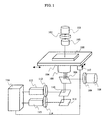
- FIG. 1 One example of the system configuration of a cell analysis and sorting apparatus of the invention of this application is schematically shown in Fig. 1.
- Indicated by 101 is a light source for a stereoscopic microscope.
- a halogen-based lamp is used as the light source.
- a bandpass filter 102 transmits only certain wavelengths of the light emitted from the light source for observations using the stereoscopic microscope such as a phase difference microscope.
- a condenser lens 103 introduces phase difference rings in a case where phase difference observation is made.
- the lens introduces a polarizer in a case where differential interference observation is made.
- Placed on a stage 104 is a cell analysis and sorting chip 100. An optimum position of the chip is observed by moving the stage by means of a driver device 117.
- the state inside the channel in the chip is observed with an objective lens 105. What are observed from the objective lens at this time are: (1) a stereoscopic image of each sample within the channel owing to transmitted light coming from the light source 101 and (2) a fluorescent image emitted from the sample in response to exciting light.
- Light from another light source 108 is passed through a bandpass filter 109 such that only the wavelength of the exciting light is directed to a dichroic mirror 106 and then to the objective lens.
- the exciting light is emitted from the objective lens.
- the wavelength of the light used for observation of the stereoscopic microscope image at this time is sufficiently shorter or sufficiently longer than the observed range of fluorescent wavelengths.
- the wavelength is made different from the wavelength region of the exciting light, if possible.
- the dichroic mirror 110 reflects the same wavelength of light as the wavelength of light transmitted through the bandpass filter 102.
- the fluorescent image is observed through a camera 115 by selectively transmitting only the wavelength range of fluorescent observation of the light transmitted through the objective lens by means of a mirror 111 and a bandpass filter 114.
- the images taken by the two cameras 113 and 115 are analyzed by an image processing portion 116.
- the microstructure of the sample can be identified by comparing the relative positional relationship between the two images. Also, the positions at which fluorescences are emitted can be compared and identified.
- comparison and analysis are performed by observing a stereoscopic image in one wavelength range and a fluorescent image in one wavelength range.
- stereoscopic images in two or more wavelength ranges may be compared.
- Two or more fluorescent images may be compared and analyzed.
- one or more additional dichroic mirrors, additional light sources, or additional camera observation systems may be arranged in the optical paths in the same way as in the above embodiment.
- Fig. 2 is a schematic diagram showing one example of the configuration of the optics of a cell analysis and sorting apparatus of the invention of this application, the apparatus being used to measure images of plural different wavelengths at the same time using the photosensitive surface of an additional observation camera.
- Different wavelengths of light 201, 202, and 203 sent in from the objective lens are contained in light 200.
- Plural dichroic mirrors 211, 212 and a mirror 213 are disposed in the direction of travel of the light 200.
- fields of view to be observed are selected by slits 221, 222, and 223 disposed in focal planes in the positions of the same optical path length.
- the strengths of the wavelengths of light are made substantially equal by bandpass filters 231, 232, and 233 and optical attenuation filters 241, 242, and 243. Also, the certain wavelengths of light to be observed are adjusted. Where certain wavelengths of light should be blocked off by shutters 251, 252, and 253, the blocking can be done. Light transmitted through the shutters again pass through the mirror 261 and the dichroic mirrors 262 and 263. Then, the light is focused onto the photosensitive surface of a camera 272 by a lens 271. Since the mirrors 261, 262, and 263 are movable, the light can be focused arbitrarily onto any desired area on the photosensitive surface of the camera. In the embodiment described so far, a technique for analyzing light consisting of three different wavelengths has been described.
- light consisting of four or more different wavelengths can also be used.
- the photosensitive surface of only one camera is used. Consequently, it is not necessary to prepare plural expensive, high-sensitivity cameras.
- images of plural different wavelengths such as stereoscopic microscope images or fluorescent microscope images can be analyzed at the same time simply by analyzing data obtained by one photosensitive surface.
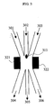
- Fig. 3 is a schematic diagram showing one example of the configuration of the sample-sorting portion of a cell analysis and sorting apparatus of this invention.
- a fluid containing a sample flows into a sample-separating portion through a channel 302.
- a fluid containing no sample flows into the sample-separating portion through other channels 301 and 303.
- Ultrasonic sources 321 and 322 are used to exert an external force on a sample 311 ultrasonically within the sample-separating portion by applying ultrasonic waves to the sample-separating portion where the three channels meet.
- Streams of fluid introduced from the channels 301, 302, and 303 are so adjusted that the fluid has no pulsation and that their fluid velocities are made coincident. Therefore, the laminar flow is maintained in the sample-separating portion.
- the sample 311 introduced into the sample-separating portion from the channel 302 travels to the channel 305 unless the sample undergoes an external force. Conversely, where an external force owing to the ultrasonic waves acts, the sample is discarded into the channel 304 or channel 305.
- the channel 302 for introducing the sample and the channel 305 for recovering the sample are aligned on a line along the direction of flow.
- the channels 301 and 303 for introducing only a pair of streams of fluid into the sample-separating portion are arranged symmetrically with respect to the axis of the aligned channels.
- the pair of channels 304 and 306 for discarding unwanted samples are arranged axisymmetrically with respect to the channel 305. At least the channels 301 and 303 show the same cross-sectional area with respect to the flow. Also, the channels 304 and 306 show the same cross-sectional area with respect to the flow.
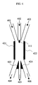
- Fig. 4 is a schematic diagram showing one example of the configuration of the sample-sorting portion similarly to Fig. 3.
- An example of a technique of directing an external force to the sample electrostatically instead of ultrasonically is shown.
- a fluid containing a sample 411 and introduced from a channel 402 is similarly introduced into the sample-separating portion, and a decision is made based on the result of a measurement using an optical measuring technique as to whether the sample is to be recovered or discarded. Where it is recovered, no external force is applied.
- the sample is made to travel intact into the channel 405 and recovered. Where the sample is discarded, an electric field is applied to electrodes 421 and 422 to direct the sample to the channel 404 or 406.
- electrodes 423 and 424 are grounded such that they act as reference electrodes.
- a substance within an aqueous solution has a zeta potential at the boundary surface with the aqueous solution.
- the substance has an electric charge arising from this potential. Accordingly, an external force can be applied to the discarded sample by causing the electric field to act on the sample.
- samples having positive charge and samples having negative charge can be separated into the channels 404 and 406.
- the bubbles have no surface charge. Therefore, the air bubbles are not affected by the electric field.
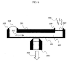
- Fig. 5 is a cross-sectional view of an example of the cell analysis and sorting chip of the invention of this application.
- Chip cross sections 501 and 503 have sufficient transparency to the observed wavelength of light.
- the thickness of the top surface 501 may be of the millimeter order to maintain the structure.
- the maximum thickness is limited according to the magnification of the objective lens. For example, where an objective lens having a numerical aperture of 1.35 and a magnification of 100 times is used as the objective lens 504, the thickness of the cross section is preferably set to less than 0.2 mm.
- Water repellency has been imparted to the sample liquid introduction portion and to the ends 509 of the chip opening of the recover portion. Processing has been done to prevent the liquid in the opening portion from diffusing.
- a sample liquid 510 is placed on the sample introduction portion.
- a seal 507 is broken by sticking a needle 508 into it.
- the sample liquid begins to flow at a flow velocity corresponding to the height of the liquid surface of the sample liquid 510.
- a flow having a strictly controlled flow velocity and having no pulsation can be created by strictly controlling the amount of the sample liquid.
- a device such as a pump is not required.
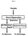
- Fig. 6 is a diagram illustrating a procedure for analyzing and sorting cells in accordance with the invention of this application.
- each sample introduced into a channel is observed with a microscope and a decision is made as to whether the sample is to be recovered or discarded.
- it is made to travel directly to the recovery channel without applying any external force at all, and then the sample is recovered.
- the sample travels through a laminar flow. It is considered that the sample that is least damaged is recovered because no external force is applied at all. Where the sample is discarded, no problems will take place if the cell is damaged. Therefore, the sample is discharged by causing an arbitrary external force to act on the sample.
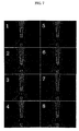
- Fig. 7 shows microscope photographs of examples of samples having actually different fluorescences, the examples being obtained by image-processing and sorting the samples by a cell analysis and sorting apparatus of the invention of this application.
- the cross section of each channel was 20 m ⁇ (wide) ⁇ 20 ⁇ m (high or deep). The ratio of their flow rates was 1:1:1.
- the kind of the cells was equine red blood cell.
- a physiological salt solution (0.9% NaCl: pH 7.4) was used as a fluid.
- An electric field induced electrophoretic force
- Photographs 1 to 4 show a process in which cells having a size of 3 micrometers and emitting red fluorescent light are recovered.
- photographs 5 to 8 show a process in which cells having a size of 3 micrometers and emitting green fluorescent light are discarded.
- the invention of this application permits minute samples to be identified, sorted, and recovered without damaging them.
Landscapes
- Chemical & Material Sciences (AREA)
- Dispersion Chemistry (AREA)
- Physics & Mathematics (AREA)
- Health & Medical Sciences (AREA)
- Life Sciences & Earth Sciences (AREA)
- Analytical Chemistry (AREA)
- Biochemistry (AREA)
- General Health & Medical Sciences (AREA)
- General Physics & Mathematics (AREA)
- Immunology (AREA)
- Pathology (AREA)
- Investigating, Analyzing Materials By Fluorescence Or Luminescence (AREA)
- Investigating Or Analysing Biological Materials (AREA)
Applications Claiming Priority (3)
| Application Number | Priority Date | Filing Date | Title |
|---|---|---|---|
| JP2002245902A JP3898103B2 (ja) | 2002-08-26 | 2002-08-26 | 細胞分析分離装置 |
| JP2002245902 | 2002-08-26 | ||
| PCT/JP2003/010760 WO2004019033A1 (fr) | 2002-08-26 | 2003-08-26 | Dispositif d'analyse et de separation de cellules |
Publications (2)
| Publication Number | Publication Date |
|---|---|
| EP1542007A1 true EP1542007A1 (fr) | 2005-06-15 |
| EP1542007A4 EP1542007A4 (fr) | 2009-02-18 |
Family
ID=31944206
Family Applications (1)
| Application Number | Title | Priority Date | Filing Date |
|---|---|---|---|
| EP03792842A Withdrawn EP1542007A4 (fr) | 2002-08-26 | 2003-08-26 | Dispositif d'analyse et de separation de cellules |
Country Status (5)
| Country | Link |
|---|---|
| US (1) | US20060073076A1 (fr) |
| EP (1) | EP1542007A4 (fr) |
| JP (1) | JP3898103B2 (fr) |
| CN (1) | CN1678908A (fr) |
| WO (1) | WO2004019033A1 (fr) |
Cited By (3)
| Publication number | Priority date | Publication date | Assignee | Title |
|---|---|---|---|---|
| US20110271746A1 (en) * | 2010-05-06 | 2011-11-10 | Sony Corporation | Microparticle sorting apparatus, microchip and microchip module |
| EP1677094A3 (fr) * | 2004-12-28 | 2013-05-29 | Japan Science and Technology Agency | Puce de mesure et de classement de cellules |
| US8703457B2 (en) | 2003-05-19 | 2014-04-22 | On-Chip Cellomics Consortium Co., Ltd. | Cell separation apparatus |
Families Citing this family (20)
| Publication number | Priority date | Publication date | Assignee | Title |
|---|---|---|---|---|
| JP4047336B2 (ja) * | 2005-02-08 | 2008-02-13 | 独立行政法人科学技術振興機構 | ゲル電極付セルソーターチップ |
| EP2172540A1 (fr) * | 2007-06-14 | 2010-04-07 | Mitsui Engineering & Shipbuilding Co., Ltd. | Cytomètre de flux doté d'une fonction de fractionnement des cellules et procédé de fractionnement de cellules vivantes |
| JP4525725B2 (ja) | 2007-10-18 | 2010-08-18 | ソニー株式会社 | 光学測定部、光学測定用部材、及びこれらを配設した微小粒子測定装置、並びに微小粒子の光学測定方法 |
| JP2009162650A (ja) | 2008-01-08 | 2009-07-23 | Sony Corp | 光学的測定装置 |
| JP4600573B2 (ja) | 2008-05-29 | 2010-12-15 | ソニー株式会社 | 光学的測定装置、並びに光検出器の波長校正方法及び光学的測定方法 |
| JP2010038866A (ja) | 2008-08-08 | 2010-02-18 | Sony Corp | マイクロチップ、微小粒子分取装置及び送流方法 |
| WO2010077205A1 (fr) * | 2009-01-05 | 2010-07-08 | Ge Healthcare Bio-Sciences Corp | Système et procédé pour obtenir simultanément une pluralité d'images dans un système d'imagerie |
| US8900854B2 (en) | 2009-03-31 | 2014-12-02 | Kanagawa Academy Of Science And Technology | Liquid reflux high-speed gene amplification device |
| JP2010252785A (ja) * | 2009-03-31 | 2010-11-11 | Kanagawa Acad Of Sci & Technol | 細胞濃縮分離装置 |
| US20110020855A1 (en) * | 2009-07-21 | 2011-01-27 | Masataka Shinoda | Method and apparatus for performing cytometry |
| US8248604B2 (en) | 2009-09-24 | 2012-08-21 | On-Chip Biotechnologies Co., Ltd | Flow cytometer and flow cell for the same |
| WO2012027366A2 (fr) | 2010-08-23 | 2012-03-01 | President And Fellows Of Harvard College | Ondes acoustiques en microfluidique |
| WO2012060163A1 (fr) | 2010-11-01 | 2012-05-10 | 財団法人神奈川科学技術アカデミー | Analyseur de cellules |
| EP2832845A1 (fr) | 2012-03-30 | 2015-02-04 | Kanagawa Academy Of Science And Technology | Trieur de cellules par imagerie |
| GB2528632A (en) * | 2014-04-30 | 2016-02-03 | Cambridge Entpr Ltd | Fluidic analysis and separation |
| US11559806B2 (en) | 2015-08-27 | 2023-01-24 | President And Fellows Of Harvard College | Acoustic wave sorting |
| CN109328098A (zh) * | 2016-06-20 | 2019-02-12 | 凸版印刷株式会社 | 液体介质的置换方法及用于该方法的流路设备 |
| US11701658B2 (en) | 2019-08-09 | 2023-07-18 | President And Fellows Of Harvard College | Systems and methods for microfluidic particle selection, encapsulation, and injection using surface acoustic waves |
| EP4006525A4 (fr) | 2019-08-21 | 2023-08-16 | Waseda University | Système et méthode d'analyse de cellules |
| US11873475B2 (en) * | 2020-01-03 | 2024-01-16 | Bioloomics, Inc. | Systems and methods for cell sorting and cell extraction |
Citations (4)
| Publication number | Priority date | Publication date | Assignee | Title |
|---|---|---|---|---|
| US4175662A (en) * | 1977-04-12 | 1979-11-27 | Tibor Zold | Method and device for sorting particles suspended in an electrolyte |
| JPH07270302A (ja) * | 1994-03-30 | 1995-10-20 | Toa Medical Electronics Co Ltd | イメージングフローサイトメータ |
| WO1998010267A1 (fr) * | 1996-09-04 | 1998-03-12 | Technical University Of Denmark | Systeme a microdebit pour separation et analyse de particules |
| JP2001165939A (ja) * | 1999-12-10 | 2001-06-22 | Asahi Kasei Corp | キャピラリー分析装置 |
Family Cites Families (6)
| Publication number | Priority date | Publication date | Assignee | Title |
|---|---|---|---|---|
| JP2749906B2 (ja) * | 1989-10-04 | 1998-05-13 | キヤノン株式会社 | 粒子測定装置 |
| EP0786078B1 (fr) * | 1994-10-14 | 2004-01-07 | University of Washington | Procede et systeme de cytometrie permettant une formation tres radipe de goutelettes |
| US6248590B1 (en) * | 1998-02-27 | 2001-06-19 | Cytomation, Inc. | Method and apparatus for flow cytometry |
| US6249341B1 (en) * | 1999-01-25 | 2001-06-19 | Amnis Corporation | Imaging and analyzing parameters of small moving objects such as cells |
| US6778724B2 (en) * | 2000-11-28 | 2004-08-17 | The Regents Of The University Of California | Optical switching and sorting of biological samples and microparticles transported in a micro-fluidic device, including integrated bio-chip devices |
| US6808075B2 (en) * | 2002-04-17 | 2004-10-26 | Cytonome, Inc. | Method and apparatus for sorting particles |
-
2002
- 2002-08-26 JP JP2002245902A patent/JP3898103B2/ja not_active Expired - Fee Related
-
2003
- 2003-08-26 US US10/525,875 patent/US20060073076A1/en not_active Abandoned
- 2003-08-26 EP EP03792842A patent/EP1542007A4/fr not_active Withdrawn
- 2003-08-26 CN CN03820191.7A patent/CN1678908A/zh active Pending
- 2003-08-26 WO PCT/JP2003/010760 patent/WO2004019033A1/fr active Application Filing
Patent Citations (4)
| Publication number | Priority date | Publication date | Assignee | Title |
|---|---|---|---|---|
| US4175662A (en) * | 1977-04-12 | 1979-11-27 | Tibor Zold | Method and device for sorting particles suspended in an electrolyte |
| JPH07270302A (ja) * | 1994-03-30 | 1995-10-20 | Toa Medical Electronics Co Ltd | イメージングフローサイトメータ |
| WO1998010267A1 (fr) * | 1996-09-04 | 1998-03-12 | Technical University Of Denmark | Systeme a microdebit pour separation et analyse de particules |
| JP2001165939A (ja) * | 1999-12-10 | 2001-06-22 | Asahi Kasei Corp | キャピラリー分析装置 |
Non-Patent Citations (4)
| Title |
|---|
| FIEDLER S ET AL: "DIELECTROPHORETIC SORTING OF PARTICLES AND CELLS IN A MICROSYSTEM" ANALYTICAL CHEMISTRY, AMERICAN CHEMICAL SOCIETY. COLUMBUS, US, vol. 70, no. 9, 1 May 1998 (1998-05-01), pages 1909-1915, XP000755524 ISSN: 0003-2700 * |
| ICHIKI T ET AL: "Development of bio-MEMS devices for single cell expression analysis" MICROPROCESSES AND NANOTECHNOLOGY CONFERENCE, 2001 INTERNATIONAL OCT. 31 - NOV. 2, 2001, PISCATAWAY, NJ, USA,IEEE, 31 October 2001 (2001-10-31), pages 190-191, XP010577435 ISBN: 978-4-89114-017-5 * |
| See also references of WO2004019033A1 * |
| T. ICHIKI, T. UJIE, T. HARA, Y. HORIIKE, K. YASUDA: "On-chip cell sorter for single cell expression analysis" MICRO TOTAL ANALYSIS SYSTEMS, 2001, pages 271-122273, XP008100130 * |
Cited By (4)
| Publication number | Priority date | Publication date | Assignee | Title |
|---|---|---|---|---|
| US8703457B2 (en) | 2003-05-19 | 2014-04-22 | On-Chip Cellomics Consortium Co., Ltd. | Cell separation apparatus |
| EP1677094A3 (fr) * | 2004-12-28 | 2013-05-29 | Japan Science and Technology Agency | Puce de mesure et de classement de cellules |
| US20110271746A1 (en) * | 2010-05-06 | 2011-11-10 | Sony Corporation | Microparticle sorting apparatus, microchip and microchip module |
| US8657121B2 (en) * | 2010-05-06 | 2014-02-25 | Sony Corporation | Microparticle sorting apparatus, microchip and microchip module |
Also Published As
| Publication number | Publication date |
|---|---|
| US20060073076A1 (en) | 2006-04-06 |
| WO2004019033A1 (fr) | 2004-03-04 |
| JP3898103B2 (ja) | 2007-03-28 |
| JP2004085323A (ja) | 2004-03-18 |
| EP1542007A4 (fr) | 2009-02-18 |
| CN1678908A (zh) | 2005-10-05 |
Similar Documents
| Publication | Publication Date | Title |
|---|---|---|
| EP1542007A1 (fr) | Dispositif d'analyse et de separation de cellules | |
| US11480516B2 (en) | Method and system for microfluidic particle sorting | |
| US9109197B2 (en) | Device for concentrating and separating cells | |
| JP5320510B2 (ja) | 細胞分析装置 | |
| KR100700437B1 (ko) | 세포분리장치 | |
| US20060177348A1 (en) | Cell sorter chip having gel electrodes | |
| US20150132766A1 (en) | Imaging cell sorter | |
| EP3109616A1 (fr) | Procede et appareil de tri de cellules | |
| US9420148B2 (en) | High-throughput single-cell imaging, sorting, and isolation | |
| JP2007504446A (ja) | マイクロ流体チャネルネットワークにおいて光学スイッチを用いて細胞をソーティングするための方法および装置 | |
| WO2018216269A1 (fr) | Procédé d'optimisation de conditions d'aspiration de microparticules, et dispositif de séparation de microparticules | |
| JP5098650B2 (ja) | 微小粒子の送流方法及び分析方法、並びに微小粒子分析用基板 | |
| US11480508B2 (en) | Systems and methods for detecting particles in a fluid channel | |
| Sugino et al. | Integration in a multilayer microfluidic chip of 8 parallel cell sorters with flow control by sol–gel transition of thermoreversible gelation polymer | |
| US20220299420A1 (en) | Systems and methods for image cytometry | |
| JP2014183854A (ja) | 細胞分析装置 | |
| Lin et al. | Microfluidic Cell Counter/Sorter Utilizing Laser Tweezers and Multiple Particle Tracing Technique |
Legal Events
| Date | Code | Title | Description |
|---|---|---|---|
| PUAI | Public reference made under article 153(3) epc to a published international application that has entered the european phase |
Free format text: ORIGINAL CODE: 0009012 |
|
| 17P | Request for examination filed |
Effective date: 20050321 |
|
| AK | Designated contracting states |
Kind code of ref document: A1 Designated state(s): AT BE BG CH CY CZ DE DK EE ES FI FR GB GR HU IE IT LI LU MC NL PT RO SE SI SK TR |
|
| RIN1 | Information on inventor provided before grant (corrected) |
Inventor name: ICHIKI, TAKANORI Inventor name: YASUDA, KENJI |
|
| A4 | Supplementary search report drawn up and despatched |
Effective date: 20090116 |
|
| 17Q | First examination report despatched |
Effective date: 20091008 |
|
| STAA | Information on the status of an ep patent application or granted ep patent |
Free format text: STATUS: THE APPLICATION IS DEEMED TO BE WITHDRAWN |
|
| 18D | Application deemed to be withdrawn |
Effective date: 20100219 |