Technical Field
-
The invention of this application relates to a novel cell analysis and
sorting apparatus permitting easy analysis and sorting of cell samples without
damage to the cells.
Background Art
-
Separating and recovering certain cells in a culture solution is an
important technique in biological and medical analyses. Where cells are sorted
by differences in specific gravity, the sorting can be carried out by sedimentometry.
However, in a case where cells do not have sufficient differences to discriminate
non-sensitized cells from sensitized cells, it is necessary to sort cells one by one
based on information obtained either by staining with a fluorescent antibody or by
visual observation. For example, a cell sorter is available as this technique. The
cell sorter is the following technique. Each individual, fluorescently stained cell is
isolated into a liquid drop to which an electric charge is imparted. Based on the
presence or absence of fluorescence from the cell in the liquid drop or based on the
amount of scattering light, a high electric field is applied in an arbitrary direction
perpendicularly to the direction of dropping while the drop is falling to thereby
control the direction of dropping of the liquid drop. In this way, the cells are
separately recovered in a plurality of containers placed underneath. This
technique is reported in detail by Kamarck, M.E., in Methods Enzymol., Vol. 151,
pp. 150-165, (1987).
-
However, this technique has some problems. It is expensive. The
equipment is large in size. A high electric field of thousands of volts is required.
A large amount of sample is necessitated. At the stage when liquid drops are
created, there is a possibility that the cells are damaged. It is impossible to
directly observe the samples. Therefore, in recent years, a cell sorter has been
invented in which fine particles flowing through a laminar flow formed in a
microscopic channel fabricated using microlithography are sorted while being
directly observed with a microscope. This is reported, for example, in Micro
Total Analysis, '98, pp. 77-80 (Kluwer Academic Publishers, 1998) or in Analytical
Chemistry, 70, pp. 1909-1915 (1998). However, the response speed of the sample
sorting is low relative to the observational means. To commercialize this
technique, a method of processing samples at a high response speed without
damage to them is required. Also, the inventor of this application and others
have made attempts to solve the problems with the prior art.
-
The attempt by the inventor and others is to perform sorting by
fluorescent observation. This technique has features and is more beneficial than
the prior art method. Nonetheless, the actual situation is that none of optical
measuring means, means for introducing samples, separation method, and so on
have been yet discussed in detail. Therefore, if only fluorescent observation is
performed, it is possible to discern samples emitting fluorescent light. However,
passage of samples emitting no fluorescent light cannot be recognized. Where
only fluorescence-labeled samples are recovered, there is a possibility that samples
emitting no fluorescent light are erroneously recovered.
-
Accordingly, it is an object of the invention of this application is to
provide a novel cell analysis and sorting apparatus which solves the prior
problems described so far, sorts samples based on microstructures of the samples
and on the fluorescent distribution within each sample, and can sort and analyze
cell samples easily without damage to recovered samples.
Disclosure of Invention
-
A first aspect of the invention of this application which solves the
foregoing problems provides a cell analysis and sorting apparatus comprising: a
channel into which a fluid containing samples is introduced, the samples being
introduced into a sample-separating portion by a laminar flow; a pair of fluid
passages arranged symmetrically on both sides of the channel, a pair of streams of
fluid made to meet in the sample-separating portion being introduced into the
fluid passages; means for introducing an external force to the sample-separating
portion only when an observed sample is discharged out of the sample-separating
portion; a sample recovery channel disposed downstream of the channel into
which the samples are introduced such that the fluid containing a sample selected
from the sample-separating portion flows out in a laminar flow; and a pair of fluid
channels which are arranged symmetrically on both sides of the sample recovery
channel and into which unwanted samples are discharged. Consequently, the
recovered cell samples are prevented from being damaged.
-
A second aspect of the invention of this application has means capable of
making at least one stereoscopic microscope image and one fluorescent microscope
image correspond to each other at the same time by referring to their mutual
positional relationship when samples within an apparatus are observed with an
optical microscope in order to sort the samples based on microstructures of the
samples and on fluorescent distribution in each sample. A third aspect provides
means for producing a flow of low fluid velocity within the apparatus without
producing pulsed flow and without using a pump or similar means. For this
purpose, there is provided means making use of a flow produced by gravity
according to differences in height between liquid drops introduced into the
apparatus.
Brief Description of Drawings
-
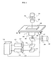
- Fig. 1 is a schematic view showing one example of a system configuration
of a cell analysis and sorting apparatus of this invention;
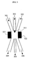
- Fig. 2 is a schematic diagram showing one example of the configuration of
optics of a cell analysis and sorting apparatus of this invention;
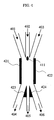
- Fig. 3 is a schematic view showing one example of the configuration of the
sample-sorting portion of a cell analysis and sorting apparatus of this invention;
- Fig. 4 is a schematic view showing one example of the configuration of the
sample-sorting portion of a cell analysis and sorting apparatus of this invention;
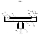
- Fig. 5 is a cross-sectional view of an example of a cell analysis and sorting
chip of this invention;
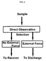
- Fig. 6 is a diagram illustrating a procedure for analyzing and sorting cells
in accordance with this invention; and
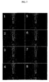
- Fig. 7 shows microscope images of one example of a method of sorting
cells by the use of a cell analysis and sorting apparatus of this invention.
-
-
The symbols used in the figures are as follows.
- 100:
- cell analysis and sorting chip;
- 101, 108:
- light sources;
- 102, 109, 112, 114, 231, 232, 233:
- bandpass filters;
- 103:
- condenser lens;
- 104:
- stage;
- 105, 504:
- objective lenses;
- 106, 110, 211, 212, 262, 263:
- dichroic mirrors;
- 111, 213, 261:
- mirrors;
- 113, 115, 272:
- cameras;
- 116:
- image processing and analysis portion;
- 117:
- driver device;
- 200, 201, 202, 203, 506:
- directions of travel of light;
- 221, 222, 223:
- slits;
- 241, 242, 243:
- optical attenuation filters;
- 251, 252, 253:
- shutters;
- 271:
- lens;
- 301, 302, 303, 304, 305, 306, 401,
402, 403, 404, 405, 406:
- channels or fluid
passages;
- 311, 411:
- samples;
- 321, 322:
- ultrasonic sources;
- 421, 422, 423, 424:
- electrodes;
- 501, 503:
- chip cross sections;
- 502:
- liquid layer;
- 505:
- flow of fluid;
- 507:
- seal;
- 508:
- needle;
- 509:
- ends of opening of chip;
- 510:
- sample liquid;
Best Mode for Carrying Out the Invention
-
The invention of this application has the features described above.
Embodiment thereof are hereinafter described.
-
One example of the system configuration of a cell analysis and sorting
apparatus of the invention of this application is schematically shown in Fig. 1.
Indicated by 101 is a light source for a stereoscopic microscope. Generally, a
halogen-based lamp is used as the light source. A bandpass filter 102 transmits
only certain wavelengths of the light emitted from the light source for observations
using the stereoscopic microscope such as a phase difference microscope. A
condenser lens 103 introduces phase difference rings in a case where phase
difference observation is made. The lens introduces a polarizer in a case where
differential interference observation is made. Placed on a stage 104 is a cell
analysis and sorting chip 100. An optimum position of the chip is observed by
moving the stage by means of a driver device 117. The state inside the channel in
the chip is observed with an objective lens 105. What are observed from the
objective lens at this time are: (1) a stereoscopic image of each sample within the
channel owing to transmitted light coming from the light source 101 and (2) a
fluorescent image emitted from the sample in response to exciting light. Light
from another light source 108 is passed through a bandpass filter 109 such that
only the wavelength of the exciting light is directed to a dichroic mirror 106 and
then to the objective lens. Thus, the exciting light is emitted from the objective
lens. The wavelength of the light used for observation of the stereoscopic
microscope image at this time is sufficiently shorter or sufficiently longer than the
observed range of fluorescent wavelengths. Preferably, the wavelength is made
different from the wavelength region of the exciting light, if possible. Only the
stereoscopic microscope image of inside the channel is observed through a camera
113 via a dichroic mirror 110 and a bandpass filter 112. The dichroic mirror 110
reflects the same wavelength of light as the wavelength of light transmitted
through the bandpass filter 102. On the other hand, the fluorescent image is
observed through a camera 115 by selectively transmitting only the wavelength
range of fluorescent observation of the light transmitted through the objective lens
by means of a mirror 111 and a bandpass filter 114. The images taken by the two
cameras 113 and 115 are analyzed by an image processing portion 116. The
microstructure of the sample can be identified by comparing the relative positional
relationship between the two images. Also, the positions at which fluorescences
are emitted can be compared and identified. In this embodiment, comparison and
analysis are performed by observing a stereoscopic image in one wavelength range
and a fluorescent image in one wavelength range. Similarly, stereoscopic images
in two or more wavelength ranges may be compared. Two or more fluorescent
images may be compared and analyzed. For these purposes, one or more
additional dichroic mirrors, additional light sources, or additional camera
observation systems may be arranged in the optical paths in the same way as in the
above embodiment.
-
Fig. 2 is a schematic diagram showing one example of the configuration
of the optics of a cell analysis and sorting apparatus of the invention of this
application, the apparatus being used to measure images of plural different
wavelengths at the same time using the photosensitive surface of an additional
observation camera. Different wavelengths of light 201, 202, and 203 sent in from
the objective lens are contained in light 200. Plural dichroic mirrors 211, 212 and
a mirror 213 are disposed in the direction of travel of the light 200. With respect
to the light split by these wavelengths, fields of view to be observed are selected by
slits 221, 222, and 223 disposed in focal planes in the positions of the same optical
path length. The strengths of the wavelengths of light are made substantially
equal by bandpass filters 231, 232, and 233 and optical attenuation filters 241, 242,
and 243. Also, the certain wavelengths of light to be observed are adjusted.
Where certain wavelengths of light should be blocked off by shutters 251, 252, and
253, the blocking can be done. Light transmitted through the shutters again pass
through the mirror 261 and the dichroic mirrors 262 and 263. Then, the light is
focused onto the photosensitive surface of a camera 272 by a lens 271. Since the
mirrors 261, 262, and 263 are movable, the light can be focused arbitrarily onto
any desired area on the photosensitive surface of the camera. In the embodiment
described so far, a technique for analyzing light consisting of three different
wavelengths has been described. Similarly, light consisting of four or more
different wavelengths can also be used. In this embodiment, the photosensitive
surface of only one camera is used. Consequently, it is not necessary to prepare
plural expensive, high-sensitivity cameras. In addition, where it is difficult to
synchronize plural cameras such as high-speed cameras, images of plural different
wavelengths such as stereoscopic microscope images or fluorescent microscope
images can be analyzed at the same time simply by analyzing data obtained by one
photosensitive surface.
-
Fig. 3 is a schematic diagram showing one example of the configuration of
the sample-sorting portion of a cell analysis and sorting apparatus of this
invention. A fluid containing a sample flows into a sample-separating portion
through a channel 302. A fluid containing no sample flows into the
sample-separating portion through other channels 301 and 303. Ultrasonic
sources 321 and 322 are used to exert an external force on a sample 311
ultrasonically within the sample-separating portion by applying ultrasonic waves
to the sample-separating portion where the three channels meet. Streams of fluid
introduced from the channels 301, 302, and 303 are so adjusted that the fluid has
no pulsation and that their fluid velocities are made coincident. Therefore, the
laminar flow is maintained in the sample-separating portion. The sample 311
introduced into the sample-separating portion from the channel 302 travels to the
channel 305 unless the sample undergoes an external force. Conversely, where an
external force owing to the ultrasonic waves acts, the sample is discarded into the
channel 304 or channel 305. At this time, the channel 302 for introducing the
sample and the channel 305 for recovering the sample are aligned on a line along
the direction of flow. The channels 301 and 303 for introducing only a pair of
streams of fluid into the sample-separating portion are arranged symmetrically
with respect to the axis of the aligned channels. Similarly, the pair of channels
304 and 306 for discarding unwanted samples are arranged axisymmetrically with
respect to the channel 305. At least the channels 301 and 303 show the same
cross-sectional area with respect to the flow. Also, the channels 304 and 306 show
the same cross-sectional area with respect to the flow.
-
Fig. 4 is a schematic diagram showing one example of the configuration of
the sample-sorting portion similarly to Fig. 3. An example of a technique of
directing an external force to the sample electrostatically instead of ultrasonically
is shown. A fluid containing a sample 411 and introduced from a channel 402 is
similarly introduced into the sample-separating portion, and a decision is made
based on the result of a measurement using an optical measuring technique as to
whether the sample is to be recovered or discarded. Where it is recovered, no
external force is applied. The sample is made to travel intact into the channel 405
and recovered. Where the sample is discarded, an electric field is applied to
electrodes 421 and 422 to direct the sample to the channel 404 or 406. At this
time, electrodes 423 and 424 are grounded such that they act as reference
electrodes. Generally, a substance within an aqueous solution has a zeta potential
at the boundary surface with the aqueous solution. The substance has an electric
charge arising from this potential. Accordingly, an external force can be applied
to the discarded sample by causing the electric field to act on the sample.
Especially, in this case, samples having positive charge and samples having
negative charge can be separated into the channels 404 and 406. Furthermore,
where the introduced sample contains air bubbles, the bubbles have no surface
charge. Therefore, the air bubbles are not affected by the electric field.
Optically speaking, however, it is often difficult to discriminate air bubbles from
liposomes and the like. However, it is possible to discriminate between air
bubbles and sample particulates using this technique.
-
Fig. 5 is a cross-sectional view of an example of the cell analysis and
sorting chip of the invention of this application. Chip cross sections 501 and 503
have sufficient transparency to the observed wavelength of light. The thickness of
the top surface 501 may be of the millimeter order to maintain the structure.
With respect to the chip cross section 503 which makes contact with an objective
lens 504 to observe flow 505 of fluid within a liquid layer 502, the maximum
thickness is limited according to the magnification of the objective lens. For
example, where an objective lens having a numerical aperture of 1.35 and a
magnification of 100 times is used as the objective lens 504, the thickness of the
cross section is preferably set to less than 0.2 mm. Water repellency has been
imparted to the sample liquid introduction portion and to the ends 509 of the chip
opening of the recover portion. Processing has been done to prevent the liquid in
the opening portion from diffusing. A sample liquid 510 is placed on the sample
introduction portion. A seal 507 is broken by sticking a needle 508 into it. Thus,
the sample liquid begins to flow at a flow velocity corresponding to the height of
the liquid surface of the sample liquid 510. At this time, a flow having a strictly
controlled flow velocity and having no pulsation can be created by strictly
controlling the amount of the sample liquid. In this technique, a device such as a
pump is not required.
-
Fig. 6 is a diagram illustrating a procedure for analyzing and sorting cells
in accordance with the invention of this application. As described previously in
the above embodiment, each sample introduced into a channel is observed with a
microscope and a decision is made as to whether the sample is to be recovered or
discarded. With respect to each recovered sample, it is made to travel directly to
the recovery channel without applying any external force at all, and then the
sample is recovered. At this time, the sample travels through a laminar flow. It
is considered that the sample that is least damaged is recovered because no
external force is applied at all. Where the sample is discarded, no problems will
take place if the cell is damaged. Therefore, the sample is discharged by causing
an arbitrary external force to act on the sample.
-
Fig. 7 shows microscope photographs of examples of samples having
actually different fluorescences, the examples being obtained by image-processing
and sorting the samples by a cell analysis and sorting apparatus of the invention of
this application. With respect to the size of each channel, the cross section of each
channel was 20 mµ (wide) × 20 µm (high or deep). The ratio of their flow rates
was 1:1:1. The kind of the cells was equine red blood cell. A physiological salt
solution (0.9% NaCl: pH 7.4) was used as a fluid. An electric field (induced
electrophoretic force) was used as an external force. Photographs 1 to 4 show a
process in which cells having a size of 3 micrometers and emitting red fluorescent
light are recovered. Similarly, photographs 5 to 8 show a process in which cells
having a size of 3 micrometers and emitting green fluorescent light are discarded.
Industrial Applicability
-
As described in detail so far, the invention of this application permits
minute samples to be identified, sorted, and recovered without damaging them.