EP1541972A1 - Dial module, manufacturing method thereof, led display element, display module, movement module, connector module, and meter using them - Google Patents
Dial module, manufacturing method thereof, led display element, display module, movement module, connector module, and meter using them Download PDFInfo
- Publication number
- EP1541972A1 EP1541972A1 EP03751277A EP03751277A EP1541972A1 EP 1541972 A1 EP1541972 A1 EP 1541972A1 EP 03751277 A EP03751277 A EP 03751277A EP 03751277 A EP03751277 A EP 03751277A EP 1541972 A1 EP1541972 A1 EP 1541972A1
- Authority
- EP
- European Patent Office
- Prior art keywords
- dial
- module
- light source
- dial module
- meter
- Prior art date
- Legal status (The legal status is an assumption and is not a legal conclusion. Google has not performed a legal analysis and makes no representation as to the accuracy of the status listed.)
- Granted
Links
Images


Classifications
-
- G—PHYSICS
- G01—MEASURING; TESTING
- G01D—MEASURING NOT SPECIALLY ADAPTED FOR A SPECIFIC VARIABLE; ARRANGEMENTS FOR MEASURING TWO OR MORE VARIABLES NOT COVERED IN A SINGLE OTHER SUBCLASS; TARIFF METERING APPARATUS; MEASURING OR TESTING NOT OTHERWISE PROVIDED FOR
- G01D11/00—Component parts of measuring arrangements not specially adapted for a specific variable
- G01D11/24—Housings ; Casings for instruments
-
- B—PERFORMING OPERATIONS; TRANSPORTING
- B60—VEHICLES IN GENERAL
- B60K—ARRANGEMENT OR MOUNTING OF PROPULSION UNITS OR OF TRANSMISSIONS IN VEHICLES; ARRANGEMENT OR MOUNTING OF PLURAL DIVERSE PRIME-MOVERS IN VEHICLES; AUXILIARY DRIVES FOR VEHICLES; INSTRUMENTATION OR DASHBOARDS FOR VEHICLES; ARRANGEMENTS IN CONNECTION WITH COOLING, AIR INTAKE, GAS EXHAUST OR FUEL SUPPLY OF PROPULSION UNITS IN VEHICLES
- B60K35/00—Instruments specially adapted for vehicles; Arrangement of instruments in or on vehicles
- B60K35/20—Output arrangements, i.e. from vehicle to user, associated with vehicle functions or specially adapted therefor
- B60K35/21—Output arrangements, i.e. from vehicle to user, associated with vehicle functions or specially adapted therefor using visual output, e.g. blinking lights or matrix displays
- B60K35/215—Output arrangements, i.e. from vehicle to user, associated with vehicle functions or specially adapted therefor using visual output, e.g. blinking lights or matrix displays characterised by the combination of multiple visual outputs, e.g. combined instruments with analogue meters and additional displays
-
- B—PERFORMING OPERATIONS; TRANSPORTING
- B60—VEHICLES IN GENERAL
- B60K—ARRANGEMENT OR MOUNTING OF PROPULSION UNITS OR OF TRANSMISSIONS IN VEHICLES; ARRANGEMENT OR MOUNTING OF PLURAL DIVERSE PRIME-MOVERS IN VEHICLES; AUXILIARY DRIVES FOR VEHICLES; INSTRUMENTATION OR DASHBOARDS FOR VEHICLES; ARRANGEMENTS IN CONNECTION WITH COOLING, AIR INTAKE, GAS EXHAUST OR FUEL SUPPLY OF PROPULSION UNITS IN VEHICLES
- B60K35/00—Instruments specially adapted for vehicles; Arrangement of instruments in or on vehicles
- B60K35/20—Output arrangements, i.e. from vehicle to user, associated with vehicle functions or specially adapted therefor
- B60K35/28—Output arrangements, i.e. from vehicle to user, associated with vehicle functions or specially adapted therefor characterised by the type of the output information, e.g. video entertainment or vehicle dynamics information; characterised by the purpose of the output information, e.g. for attracting the attention of the driver
-
- B—PERFORMING OPERATIONS; TRANSPORTING
- B60—VEHICLES IN GENERAL
- B60K—ARRANGEMENT OR MOUNTING OF PROPULSION UNITS OR OF TRANSMISSIONS IN VEHICLES; ARRANGEMENT OR MOUNTING OF PLURAL DIVERSE PRIME-MOVERS IN VEHICLES; AUXILIARY DRIVES FOR VEHICLES; INSTRUMENTATION OR DASHBOARDS FOR VEHICLES; ARRANGEMENTS IN CONNECTION WITH COOLING, AIR INTAKE, GAS EXHAUST OR FUEL SUPPLY OF PROPULSION UNITS IN VEHICLES
- B60K35/00—Instruments specially adapted for vehicles; Arrangement of instruments in or on vehicles
- B60K35/60—Instruments characterised by their location or relative disposition in or on vehicles
-
- G—PHYSICS
- G01—MEASURING; TESTING
- G01D—MEASURING NOT SPECIALLY ADAPTED FOR A SPECIFIC VARIABLE; ARRANGEMENTS FOR MEASURING TWO OR MORE VARIABLES NOT COVERED IN A SINGLE OTHER SUBCLASS; TARIFF METERING APPARATUS; MEASURING OR TESTING NOT OTHERWISE PROVIDED FOR
- G01D11/00—Component parts of measuring arrangements not specially adapted for a specific variable
- G01D11/28—Structurally-combined illuminating devices
-
- G—PHYSICS
- G01—MEASURING; TESTING
- G01D—MEASURING NOT SPECIALLY ADAPTED FOR A SPECIFIC VARIABLE; ARRANGEMENTS FOR MEASURING TWO OR MORE VARIABLES NOT COVERED IN A SINGLE OTHER SUBCLASS; TARIFF METERING APPARATUS; MEASURING OR TESTING NOT OTHERWISE PROVIDED FOR
- G01D13/00—Component parts of indicators for measuring arrangements not specially adapted for a specific variable
- G01D13/02—Scales; Dials
- G01D13/04—Construction
-
- B—PERFORMING OPERATIONS; TRANSPORTING
- B60—VEHICLES IN GENERAL
- B60K—ARRANGEMENT OR MOUNTING OF PROPULSION UNITS OR OF TRANSMISSIONS IN VEHICLES; ARRANGEMENT OR MOUNTING OF PLURAL DIVERSE PRIME-MOVERS IN VEHICLES; AUXILIARY DRIVES FOR VEHICLES; INSTRUMENTATION OR DASHBOARDS FOR VEHICLES; ARRANGEMENTS IN CONNECTION WITH COOLING, AIR INTAKE, GAS EXHAUST OR FUEL SUPPLY OF PROPULSION UNITS IN VEHICLES
- B60K2360/00—Indexing scheme associated with groups B60K35/00 or B60K37/00 relating to details of instruments or dashboards
- B60K2360/20—Optical features of instruments
- B60K2360/33—Illumination features
- B60K2360/331—Electroluminescent elements
-
- B—PERFORMING OPERATIONS; TRANSPORTING
- B60—VEHICLES IN GENERAL
- B60K—ARRANGEMENT OR MOUNTING OF PROPULSION UNITS OR OF TRANSMISSIONS IN VEHICLES; ARRANGEMENT OR MOUNTING OF PLURAL DIVERSE PRIME-MOVERS IN VEHICLES; AUXILIARY DRIVES FOR VEHICLES; INSTRUMENTATION OR DASHBOARDS FOR VEHICLES; ARRANGEMENTS IN CONNECTION WITH COOLING, AIR INTAKE, GAS EXHAUST OR FUEL SUPPLY OF PROPULSION UNITS IN VEHICLES
- B60K2360/00—Indexing scheme associated with groups B60K35/00 or B60K37/00 relating to details of instruments or dashboards
- B60K2360/40—Hardware adaptations for dashboards or instruments
- B60K2360/42—Circuit board features
-
- H—ELECTRICITY
- H05—ELECTRIC TECHNIQUES NOT OTHERWISE PROVIDED FOR
- H05K—PRINTED CIRCUITS; CASINGS OR CONSTRUCTIONAL DETAILS OF ELECTRIC APPARATUS; MANUFACTURE OF ASSEMBLAGES OF ELECTRICAL COMPONENTS
- H05K1/00—Printed circuits
- H05K1/02—Details
- H05K1/14—Structural association of two or more printed circuits
- H05K1/141—One or more single auxiliary printed circuits mounted on a main printed circuit, e.g. modules, adapters
-
- H—ELECTRICITY
- H05—ELECTRIC TECHNIQUES NOT OTHERWISE PROVIDED FOR
- H05K—PRINTED CIRCUITS; CASINGS OR CONSTRUCTIONAL DETAILS OF ELECTRIC APPARATUS; MANUFACTURE OF ASSEMBLAGES OF ELECTRICAL COMPONENTS
- H05K1/00—Printed circuits
- H05K1/18—Printed circuits structurally associated with non-printed electric components
- H05K1/189—Printed circuits structurally associated with non-printed electric components characterised by the use of flexible or folded printed circuits
-
- H—ELECTRICITY
- H05—ELECTRIC TECHNIQUES NOT OTHERWISE PROVIDED FOR
- H05K—PRINTED CIRCUITS; CASINGS OR CONSTRUCTIONAL DETAILS OF ELECTRIC APPARATUS; MANUFACTURE OF ASSEMBLAGES OF ELECTRICAL COMPONENTS
- H05K3/00—Apparatus or processes for manufacturing printed circuits
- H05K3/0058—Laminating printed circuit boards onto other substrates, e.g. metallic substrates
-
- H—ELECTRICITY
- H10—SEMICONDUCTOR DEVICES; ELECTRIC SOLID-STATE DEVICES NOT OTHERWISE PROVIDED FOR
- H10W—GENERIC PACKAGES, INTERCONNECTIONS, CONNECTORS OR OTHER CONSTRUCTIONAL DETAILS OF DEVICES COVERED BY CLASS H10
- H10W72/00—Interconnections or connectors in packages
- H10W72/50—Bond wires
- H10W72/551—Materials of bond wires
- H10W72/552—Materials of bond wires comprising metals or metalloids, e.g. silver
- H10W72/5522—Materials of bond wires comprising metals or metalloids, e.g. silver comprising gold [Au]
-
- H—ELECTRICITY
- H10—SEMICONDUCTOR DEVICES; ELECTRIC SOLID-STATE DEVICES NOT OTHERWISE PROVIDED FOR
- H10W—GENERIC PACKAGES, INTERCONNECTIONS, CONNECTORS OR OTHER CONSTRUCTIONAL DETAILS OF DEVICES COVERED BY CLASS H10
- H10W74/00—Encapsulations, e.g. protective coatings
-
- H—ELECTRICITY
- H10—SEMICONDUCTOR DEVICES; ELECTRIC SOLID-STATE DEVICES NOT OTHERWISE PROVIDED FOR
- H10W—GENERIC PACKAGES, INTERCONNECTIONS, CONNECTORS OR OTHER CONSTRUCTIONAL DETAILS OF DEVICES COVERED BY CLASS H10
- H10W74/00—Encapsulations, e.g. protective coatings
- H10W74/10—Encapsulations, e.g. protective coatings characterised by their shape or disposition
-
- H—ELECTRICITY
- H10—SEMICONDUCTOR DEVICES; ELECTRIC SOLID-STATE DEVICES NOT OTHERWISE PROVIDED FOR
- H10W—GENERIC PACKAGES, INTERCONNECTIONS, CONNECTORS OR OTHER CONSTRUCTIONAL DETAILS OF DEVICES COVERED BY CLASS H10
- H10W90/00—Package configurations
- H10W90/701—Package configurations characterised by the relative positions of pads or connectors relative to package parts
- H10W90/751—Package configurations characterised by the relative positions of pads or connectors relative to package parts of bond wires
- H10W90/756—Package configurations characterised by the relative positions of pads or connectors relative to package parts of bond wires between a chip and a stacked lead frame, conducting package substrate or heat sink
Definitions
- the present invention relates to a dial module and process for manufacturing the dial module, LED display element, display module, movement module, connector module and meter employing the same.
- Figure 13 is an exploded perspective view illustrating an example of a conventional meter for use in a motor vehicle proposed by the applicant.
- the meter for use in a motor vehicle includes a front glass 5, plate 6, dial (i.e. dial plate) 2, casing 12, board assembly 13, and stepper motor 83b as a movement.
- a bracket, lamp casing and housing are incorporated with the casing 12.
- the dial 2 is provided with meters such as a speed meter 21, tachometer 22, thermometer 23 and fuel meter 24, and meters consisting of various indicators such as a warning display 25 on a surface of the dial 2.
- the speed meter 21 includes meter design part 21 a consisting of the scale, characters and indices, and a through hole 21b formed at the center for attaching a pointer 83f on a front surface of the dial 2 by guiding a rotation shaft of the stepper motor 83b therethrough.
- the tachometer 22 includes a meter design part 22a and through hole 22b
- the thermometer 23 includes a meter design part 23a and through hole 23b
- the fuel meter 24 includes a meter design part 24a and through hole 24b.
- a translucent paint such as a white paint is printed on each of the meter design parts 21a, 22a, 23a, 24a and 25a of the speed meter 21, tachometer 22, thermometer 23, fuel meter 24 and warning display 25, respectively.
- a light-blocking paint such as a black paint is printed on a portion except each design part.
- Each design part disperses the light from a light source (not shown in the figure) attached to the board assembly 13 by means of a lamp casing of the casing 12 so as to light up from the back.
- the meter design part 25a of the warning display 25 is illuminated by a shell-type light-emitting diode (LED) display element (not shown in the figure) mounted on the board assembly 13 as a light source when a warning is given.
- LED light-emitting diode
- an IC as a drive element for driving a LED display element for the warning display 25
- IC as a drive element for driving a LCD (liquid crystal display) as an assistant display element for displaying such as a trip meter
- IC as a drive element for driving a stepper motor 83b
- other electronic instruments for carrying out various functions of meters for a vehicle.
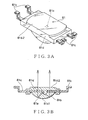
- the stepper motor 83b includes an upper casing 83b-1 and lower casing 83b-2 made of synthetic resin or the like.
- a pair of engaging holes 83b-1a of the upper casing 83b-1 engages with an engaging projection 83b-2a formed on an outer wall of the lower casing 83b-2, thereby fixing the upper and lower casings 83b-1, 83b-2 to each other.
- a rotation shaft 83b-3 for attaching a needle (indication needle) 83f penetrates through to protrude from an upper surface of the upper casing 83b-1.
- a side wall of the upper casing 83b-1 is provided with an arm-shaped hook 83b-1c in the inverse direction to the rotation shaft 83b-3.
- a bracket, lamp casing and housing are incorporated with the casing 12, and the board assembly 13 is assembled into a single board, thereby having advantages of easy assembling and simple structure.
- Figures 15 and 16 show a perspective view and cross sectional view taken along B - B line illustrating another example of a conventional meter for a vehicle.
- the meter for a vehicle includes: a display board 101 having a circuit pattern (not shown in the figure) capable of electric conduction between a front surface 101a and back surface 101b; and a display devices such as a speed meter 102, tachometer 105, fuel meter 108 and thermometer 111, each mounted on the front surface 101a of the display board 101.
- the speed meter 102 includes: a stepper motor 103 as a movement fixed to the display board 101; and a needle 104 attached to an output shaft 103a of the stepper motor 103 that functions as internal equipment for driving the needle 104 in response to measured quantity data of a speed of the vehicle.
- the tachometer 105 includes a stepper motor 106 and a needle 107 attached to an output shaft 106a of the stepper motor 106 that functions as internal equipment for driving the needle 107 in response to measured quantity data of number of revolutions of an engine.
- the fuel meter 108 includes a stepper motor 109 and a needle 110 attached to an output shaft 109a of the stepper motor 109 that functions as internal equipment for driving the needle 110 in response to measured quantity data of the amount of fuel.
- the thermometer 111 includes a stepper motor 112 and a needle 113 attached to an output shaft 112a of the stepper motor 112 that functions as internal equipment for driving the needle 113 in response to measured quantity data of temperature in a vehicle.
- a dial which is provided with a scale and indices such as numbers, characters and marks on a surface on the dial (not shown in the figure).
- the meter for a vehicle includes: an infrared light-receiving element 114 and an IC (Integrated Circuit) 115 for a stepper motor driver and infrared communication, each of which is mounted on the back surface 101b of the display board 101 and electrically connected to the speed meter 102 mounted on the front surface 101a; an infrared light-receiving element 116 and an IC (Integrated Circuit) 117 for a stepper motor driver and infrared communication, each of which is electrically connected to the tachometer 105 mounted on the front surface 101a; an infrared light-receiving element 118 and an IC (Integrated Circuit) 119 for a stepper motor driver and infrared communication, each of which is electrically connected to the fuel meter 108 mounted on the front surface 101 a; and an infrared light-receiving element 120 and an IC (Integrated Circuit) 121 for a stepper motor driver and infrared communication, each of which is electrically connected to the thermometer
- the meter for a vehicle includes a control module 122 attached to the back surface 101b of the display board 101.
- the control module 122 is provided with an IC 124 (including an I/F (interface) circuit IC, microcomputer IC and infrared communication IC) and an infrared light-emitting element 125 on a board provided with a circuit pattern (not shown in the figure).
- the control module 122 is detachably attached to the display board 101 with two fittings 123.
- the fitting 123 has a groove 123a for fitting the control module board 122 thereinto at one end thereof and four claw-shaped engaging parts 123b for resiliently engaging with corresponding engaging holes 101c of the display board 101 at the opposite end thereof.
- Each measured quantity of the vehicle speed, number of revolutions of the engine, amount of the fuel and temperature in the vehicle detected by the respective sensors are inputted into the control module 122 in a form of, for example, serial data. Then, each measured quantity is processed on the basis of the inputted data and then, each measured quantity as the quantity data labeled with a specific identification code is transmitted from the infrared light-emitting element 125 as an infrared signal.
- the infrared signal transmitted from the infrared light-emitting element 125 is received by the respective infrared light-receiving elements 114, 116, 118 and 120 and supplied to the respective IC 115, 117, 119 and 121 for a stepper motor driver and infrared communication.
- Each of the IC 115, 117, 119 and 121 for a stepper motor driver and infrared communication selectively supplies the corresponding measured quantity data of the vehicle speed, number of revolution of the engine, amount of the fuel and temperature in the vehicle to the corresponding meters, that is, the speed meter 102, tachometer 105, fuel meter 108 and thermometer 111 according to the corresponding specific identification code.
- a control section which is a basic control part for controlling the respective meters, each indicating the measured quantity as to a state of the vehicle, is made a module as the control module 122, thereby enabling to be commonly used for any meter.
- the output from the control module 122 is made to be an infrared communication output.
- the infrared light-receiving element and the corresponding IC for a stepper motor driver and infrared communication are mounted corresponding to each meter.
- each of the IC 115, 117, 119 and 121 for a stepper motor driver and infrared communication is connected to the corresponding stepper motor 103, 106, 109 and 112, each of which constitutes the corresponding meter device such as the speed meter 102, tachometer 105, fuel meter 108 and thermometer 111. Therefore, each stepper motor can be operable with the infrared signal from the control module 122.
- a structure of an integrated board is illustrated, on which integrated board each stepper motor 103, 106, 109 and 112 as the movement and each IC 115, 117, 119 and 121 for a stepper motor driver and infrared communication are mounted.
- each of the casing 12 and board assembly 13 is molded to have a predetermined shape with resin or the like as a separate part separated from the dial 2, therefore if the arrangement of the meter varies depending on a type of the vehicle, it is necessary to make separately the dial, casing and board assembly by changing their shapes depending on a type of the vehicle so as to fit to the arrangement of the meter, causing a problem that such a meter for a vehicle cannot be commonly used for various types of the vehicle.
- the integrated board for the meter for a vehicle shown in Figs. 13 - 16 has restriction for designing due to a limited wiring space. Further, a board having high mounting density must be designed separately depending on a combination or layout of the respective meters, causing a necessity of a large man-hour for designing. Further, when the board is completed, there is a problem that an evaluation of noise and so on must be carried out each time.
- the integrated board described above needs a mounting space for mounting a plurality of drive elements for carrying out the respective functions of the meter for a vehicle. Further, when the integrated board is designed as a board which can be used in common for a plurality of types of vehicle, there is a problem that a useless mounting space for a drive element for an unnecessary function occurs depending on a type of the vehicle.
- a dial module defined in claim 1 is a dial module including:
- a dial module defined in claim 2 is, in the invention defined in claim 1, characterized in that the dial, light source and flexible printed circuit are formed in substantially the same shape.
- a dial module defined in claim 3 is a dial module including:
- a dial module defined in claim 4 is, in the invention defined in claim 3, characterized in that the light source and flexible printed circuit are formed in substantially the same shape.
- a dial module defined in claim 5 is a dial module including:
- a dial module defined in claim 6 is, in the invention defined in claim 5, characterized in that the dial and light source are formed in substantially the same shape.
- a dial module defined in claim 7 is a dial module including a sheet-shaped light source, wherein a dial having a design part is formed on a front surface of the light source while a flexible printed circuit is formed on a back surface of the light source.
- a dial module defined in claim 8 is, in the invention defined in any one of claims 1 - 7, characterized in that it further includes a connecting terminal part for attaching an additional component thereto.
- a dial module defined in claim 9 is, in the invention defined in any one of claims 1 - 8, characterized in that the light source is a sheet-shaped electroluminescent light source.
- a process for manufacturing a dial module defined in claim 10 is a process for manufacturing a dial module including:
- a process for manufacturing a dial module defined in claim 11 is, in the invention defined in claim 10, characterized in that the light source is formed by providing a transparent electrically conductive film with a luminous layer, insulating layer and back surface electrode, and the flexible printed circuit is formed by providing a copper foil film with a circuit with etching followed by an insulation processing.
- a process for manufacturing a dial module defined in claim 12 is a process for manufacturing a dial module including:
- a process for manufacturing a dial module defined in claim 13 is, in the invention defined in claim 12, characterized in that it further includes a third step in which an insulation processing is applied on a part where the circuit is formed.
- a process for manufacturing a dial module defined in claim 14 is, in the invention defined in any one of claims 10 - 13, characterized in that the light source is a sheet-shaped electroluminescent light source.
- a meter defined in claim 15 is a meter including:
- a light-emitting diode (LED) display element defined in claim 16 is a light-emitting diode display element for supplying electric power to a light-emitting element, including a lead terminal for fixing the light-emitting element to an opposite attaching member situated in the same direction as that of emission from the light-emitting element.
- a light-emitting diode display element defined in claim 17 is a light-emitting diode display element including:
- a meter defined in claim 18 is a meter including:
- a display module defined in claim 19 is a display module including:
- a display module defined in claim 20 is, in the invention defined in claim 19, characterized in that the display element is a liquid crystal display element.
- a meter defined in claim 21 is a meter including:
- a movement module defined in claim 22 is a movement module including:
- a meter defined in claim 23 is a meter including:
- a connector module defined in claim 24 is a connector module including:
- a connector module defined in claim 25 is, in the invention defined in claim 24, characterized in that the part of the second connecting terminal, which part is situated inside the second tube part, is a resilient contact.
- a connector module defined in claim 26 is, in the invention defined in claim 24 or 25, characterized in that it further includes a cover for closing an opening of the second tube part.
- a meter defined in claim 27 is a meter including:
- Figure 1A is an exploded perspective view illustrating a preferred embodiment of a dial module according to the present invention.
- Figure 1B is a perspective view illustrating a preferred embodiment of an assembled dial module according to the present invention.
- the dial module (i.e. dial plate module) 1 includes a sheet-shaped dial (i.e. dial plate) 2, electroluminescence light source (hereinafter, EL light source) 3 as a sheet-shaped light source and a flexible printed circuit (hereinafter, FPC) 4.
- EL light source electroluminescence light source
- FPC flexible printed circuit
- the dial 2 consisting of, for example, sheet-shaped translucent material, is a sheet-shaped dial, in which a surface of a sheet is provided with meters such as a speed meter 21, tachometer 22, thermometer 23 and fuel meter 24 and various indicators such as a warning display 25.
- meters such as a speed meter 21, tachometer 22, thermometer 23 and fuel meter 24 and various indicators such as a warning display 25.
- a speed meter 21 is arranged at the center, a circular meter including a thermometer 23 and a fuel meter 24 is connected to one side of the speed meter 21 while another circular meter including a tachometer 22 and a warning display 25 is connected to the opposite side of the speed meter 21.
- the speed meter 21 includes: a meter design part 21a consisting of a scale, characters and indices; a through hole 21b formed at the center for guiding a rotation shaft of a stepper motor (explained later on) therethrough; and a notch 21c as a first notch formed at the lower part of the speed meter 21.
- the tachometer 22 includes a meter design part 22a and a through hole 22b
- the thermometer 23 includes a meter design part 23a and a through hole 23b
- the fuel meter 24 includes a meter design part 24a and a through hole 24b.
- a translucent paint such as a white paint is printed on each of the meter design parts 21a, 22a, 23a, 24a and 25a of the speed meter 21, tachometer 22, thermometer 23, fuel meter 24 and warning display 25, respectively.
- a light-blocking paint such as a black paint is printed on a portion except each design part.
- the EL light source 3 is a sheet-shaped light source formed substantially in the same shape as that of the dial 2.
- a part 31 corresponding to the speed meter 21, part 32 corresponding to the tachometer 22 and part 33 corresponding to the thermometer 23 and fuel meter 24 are integrally formed with one another in a linked shape.
- the part 31 includes a through hole 31a formed at the center for guiding a rotation shaft of a stepper motor therethrough and a notch 31 a as a second notch formed so as to be lined up with the notch 21c at the lower part of the part 31.
- the part 32 includes a through hole 32a while the part 33 includes through holes 33a and 33b.
- the FPC 4 is formed substantially in the same shape as that of the dial 2.
- a part 41 corresponding to the speed meter 21, part 42 corresponding to the tachometer 22 and part 43 corresponding to the thermometer 23 and fuel meter 24 are integrally formed with one another in a linked shape.
- the part 41 includes a through hole 41 a formed at the center for guiding a rotation shaft of a stepper motor therethrough and a display window 41b formed by being notched at the lower part of the part 41.
- the display window 41b is formed so as to be situated in the rear of the notches 21c and 31a.
- the part 42 includes a through hole 42a while the part 43 includes through holes 43a and 43b.
- the FPC 4 includes a circuit for carrying out the function of the meters on the dial 2, a circuit for supplying electric power to the EL light source 3, and connecting terminals for connecting electronic components (explained alter on) for carrying out the function of the meters on the dial 2. Further, the FPC 4 includes a connecting terminal 44 for attaching an optional meter, which terminal is formed being extended to the upper part of the part 42.
- the EL light source 3 is fixed on the back surface of the dial 2 by fixing means such as an adhesive, while the FPC 4 is fixed on the back surface of the EL light source 3 by fixing means such as an adhesive, thereby the dial 2, EL light source 3 and FPC 4 are integrated and the dial module 1 is completed as shown in Fig. 1B.
- the EL light source 3 receives electric power from the circuit of the FPC 4 and illuminates each design part of the dial 2 from the rear.
- the dial module 1 the dial 2, the EL light source 3 for illuminating each design part of the dial 2, and the FPC 4 having the circuits and connecting terminal for carrying out the function of the meters on the dial 2 and the electric power supply to the EL light source 3 are integrated with one another, so that the dial module 1 is formed in a flexible sheet as a whole. Therefore, the number of components can be reduced so that the assembling work of the meter employing such a dial module can be facilitated, thereby enabling the improvement in productivity and reduce in cost.
- the dial module 1 Since the dial module 1 has a flexible sheet-shaped form, it can be applied not only when all of a plurality of meters constructed by the dial 2 has a flat design but also even when a part of a plurality of meters constructed by the dial 2 has a design including some unevenness, thereby improving in the design.
- FIG. 2 is an exploded perspective view illustrating a meter for a vehicle, which employs the dial module according to the present invention.
- the meter includes a front glass 5, frame board 6, the dial module 1 of the present invention, and casing 7.
- the EL light source 3 On a surface of the FPC 4 situated on the rear side of the dial module 1, there are formed the EL light source 3 and a plurality of connecting terminals (not seen in Fig. 2 because of their positions) for connecting electronic components 8 for carrying out the function of the meters on the dial 2, wherein the EL light source 3 and the electronic components 8 such as a light-emitting diode (i.e. LED) display element 81, display module 82, movement module 83 and connector module 84 are attached to the respective connecting terminals by fixing means such as solder or electrically conductive paste.
- a light-emitting diode i.e. LED
- the LED display element 81 includes a light-emitting element 81a, gold wire 81b, a lead terminal 81c connected to the light-emitting element 81a by the gold wire 81b for supplying electric power to the light-emitting element 81a, and an epoxy resin 81d as a translucent member which is hardened after the light-emitting element 81a is encapsulated therein.
- the epoxy resin 81d is shaped so that a face facing an attaching direction by the lead terminal 81c becomes a flat emitting surface 81d2 while a face opposite to the attaching direction becomes a curved reflecting surface 81d1, which is subjected to a mirror surface processing by plating or vapor deposition with metallic material such as silver or aluminum so as to form a reflecting mirror.
- the lead terminal 81c protrudes from the side of the epoxy resin 81d and is bent toward the emitting surface 81d2. Further, an end 81c1 of the lead terminal 81c is bent so as to be flush with the emitting surface 81d2.
- the end 81c1 is fixed to a connecting terminal as an opposite attaching member of the FPC 4 by fixing means such as solder or electrically conductive paste.
- the LED display element 81 constructed as described above is a reflection-type LED display element. As shown by arrows in Fig. 3B, the emission from the light-emitting element 81a is reflected by the reflecting surface 81d1, emitted from the emitting surface 81d2, and forwarded as a parallel ray in the attaching direction to the FPC 4.
- Figure 4 is a partial cross sectional view illustrating a part of the warning display 25, in which the LED display element 81 is employed.
- the EL light source 3 situated in the rear of a part where the warning display design part 25a is formed in the warning display 25, is provided with an opening 3a as the first opening.
- the warning display design part 25a is subjected to clear coating.
- the FPC 4 is provided with an opening 4b as the second opening, which is lined up with the opening 3a.
- the LED display element 81 is arranged in the rear of the openings 3a and 4b.
- a lead terminal of the LED display element 81 is attached to a copper foil 4a as the connecting terminal of the FPC 4 by fixing means such as solder or electrically conductive paste.
- the emission from the LED display element 81 illuminates the warning display design part 25a through the openings 4b and 3a, thereby providing a warning to a driver of a vehicle.
- display module 82 includes a printed board 82a, liquid crystal display (LCD) element 82b as the display element mounted on the printed board 82a, driver element 82c consisting of IC or the like for driving the LCD element 82b, and connection terminal 82d formed on the printed board 82a.
- the LCD element 82b and driver element 82c are connected to each other by a circuit (not shown in the figure) formed on the printed board 82a and also are connected to the connection terminal 82d.
- the connecting terminal 82d of the display module 82 is attached to the corresponding connecting terminal of the FPC 4 by fixing means such as solder or electrically conductive paste so that the LCD element 82b is situated at the display window 41b formed on the FPC 4.
- the driver element 82c for driving the LCD element 82b is mounted on the side of the display module 82, therefore the number of components can be reduced. Further, since a space for mounting the driver element 82c becomes unnecessary at the side of the FPC 4, therefore the wiring becomes easy.
- each movement module 83 includes a printed board 83a, stepper motor 83b as the movement mounted on one surface of the printed board 83a, driver element 83c for driving the stepper motor 83b and LED element 83d, both mounted on the opposite surface of the printed board 83a, and connecting terminal 83e formed at an end of the printed board 83a.
- a rotation shaft 83b1 of the stepper motor 83b protrudes from the opposite side of the printed board 83a.
- the connecting terminal 83e is attached to a corresponding connecting terminal of the FPC 4 by fixing means such as solder.
- each rotation shaft 83b1 penetrates through the corresponding through holes 41a, 31b and 21b, through holes 42a, 32a and 22b, through holes 43a, 33a and 23b or through holes 43b, 33b and 24b of the dial module 1 and then, each needle 83f arranged on the front surface-side of the dial module 1 is attached to the corresponding rotation shaft 83b1.
- the driver element 83c for driving the stepper motor 83b is mounted on the side of the movement module 83, therefore the number of components can be reduced. Further, since a space for mounting the driver element 83c becomes unnecessary at the side of the FPC 4, therefore the wiring becomes easy.
- FIG. 7 is a perspective view illustrating another example of the movement module 83.
- a positioning pin 83b-5 of the stepper motor 83b is inserted into a positioning hole 83a2 formed in the printed board 83a while a fixing claw 83b-4 of the stepper motor 83b engages with an edge of an attaching hole 83a1 of the printed board 83a, thereby the stepper motor 83b is fixed to the printed board 83a.
- a connecting terminal 83e formed at an end of the printed board 83a is extended toward the opposite side of the rotation shaft 83b1 and guided by a terminal guide 83f as a separate member.
- the movement module 83 can be fixed to an opposite attaching member (not shown in the figure) situated on the opposite side of the rotation shaft 83b1 with a hook 83b-1c while the connecting terminal 83e can be connected to a corresponding connecting terminal (not shown in the figure) on the side of the opposite attaching member.
- Figure 8 is a perspective view illustrating a further example of the movement module 83.
- the stepper motor 83b is constructed so that its rotation shaft 83b1 extends in the same direction as that of the hook 83b-1c.
- a terminal guide 83a3 is integrally formed extending from an end of the printed board 83a.
- the connecting terminal 83e penetrates through the terminal guide 83a3 and is exposed to the same side as that of the rotation shaft 83b1.
- a positioning pin 83b-5 of the stepper motor 83b is inserted into a positioning hole 83a2 formed in the printed board 83a while a fixing claw 83b-4 of the stepper motor 83b engages with an edge of an attaching hole 83a1 of the printed board 83a, thereby the stepper motor 83b is fixed to the printed board 83a.
- the movement module 83 can be fixed to an opposite attaching member (not shown in the figure) situated on the same side as that of the rotation shaft 83b1 with a hook 83b-1c while the connecting terminal 83e can be connected to a corresponding connecting terminal (not shown in the figure) on the side of the opposite attaching member.
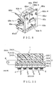
- the connector module 84 includes: a housing 84a having a tube part 84b as the first tube part and a tube part 84c as the second tube part; a cover 84f for closing an opening of the tube part 84c; a connecting terminal 84d as the first connecting terminal; and a connecting terminal 84e as the second connecting terminal.
- the connecting terminal 84d is attached so that the connecting terminal 84d penetrates through the bottom of the tube part 84b and a part thereof is situated in the tube part 84b while another part is exposed to the outside of the tube part 84b.
- the connecting terminal 84e is attached so that the connecting terminal 84e penetrates through the bottom of the tube part 84c and a part thereof is situated in the tube part 84c while another part is exposed to the outside of the tube part 84c.
- the part of the connecting terminal 84e situated in the tube part 84c is a resilient contact part.
- Each of the other parts of the connecting terminals 84d and 84e exposed to the outside of the housing 84a is attached to the corresponding connecting terminal of the FPC 4 by fixing means such as solder or the like.
- a wiring harness connector 84g as an external connector is connected to the connecting terminals 84d, while a control circuit board 84h replaceable depending on a type of a vehicle is detachably connected to the resilient contact part of the connecting terminal 84e in a slot-in manner.
- the control circuit board 84h is a circuit board on which electronic components for constructing a meter control circuit that is varied depending on a type of a vehicle are mounted.
- control circuit board 84h is mounted on the side of the connector module 84, therefore the number of components can be reduced. Even when the design of the meter is changed depending on a type of a vehicle, one can respond to it only by replacing the control circuit board 84h, that is, one can use the connector module usable in common for every type of a vehicle not being affected by a shape of the meter. Further, even when the shape of the connector is different, a common product can be used if the shape of the tube part 84c is matched. Furthermore, when the specification of the meter control circuit is changed, this change is easily carried out only by replacing the control circuit board 84h with that of a different specification. For example, when the specification of an engine is changed, when the specification of a tire is changed, and when the capacity of a gasoline tank is changed, the specification can be easily changed only by replacing the control circuit board 84h.
- the FPC 4 a space for mounting the electronic components corresponding to the control circuit board 84h becomes unnecessary, therefore the wiring becomes simple since it can be carried out only by mounting the electronic components common to every type of a vehicle. Since there is the resilient contact part of the connecting terminal 84e to be connected to the control circuit board 84h, it is easy to attach or detach the control circuit board 84h. Since the opening of the tube part 84c is closed by the cover 84f, the control circuit board 84h is prevented from coming off and from being affected by dust.
- the casing 7 includes recesses 7a matching with the shape of the dial module 1 and recesses 7b matching with the unevenness of the electronic components 8 to be mounted on the FPC 4.
- the casing 7 fixes the dial module 1, in which the electronic components 8 are mounted on the FPC 4, between the frame board 6 and the casing 7.
- the dial module 1 since the dial module 1 is employed therein, the number of components can be reduced so that the assembling work of the meter can be facilitated, thereby enabling the improvement in productivity and reduce in cost. Further, it enables to minimize the restriction for designing, to reduce the man-hour for designing a board, and to reduce the number of evaluation as to noise or the like.
- connection terminal 44 can be used when the additional circuit is necessary or when an optional meter such as an accelerometer or the like is connected thereto depending on a type of a vehicle.
- an optional meter such as an accelerometer or the like can be attached thereto by inserting a connector (not shown in the figure) of the optional meter from a direction parallel to the plane of the dial 2.
- the insertion direction is not perpendicular to the plane of the dial 2 but parallel to the plane, the sheet-shaped dial module 1 is prevented from being applied by an extra load and therefore prevented from being broken, and a space for mounting an additional component can be reduced.
- the dial module 1 is constructed by forming the dial 2, EL light source 3 and FPC 4, which are originally separate from one another, integrally with one another by fixing means such as an adhesive or the like.
- the dial module may be constructed in such a manner that a front surface of the sheet-shaped EL light source 3 is provided with a dial having a meter design part by printing or the like and the FPC 4 is fixed to a back surface of the EL light source 3 by fixing means such as an adhesive or the like.
- the FPC 4 and EL light source 3 can be formed in substantially the same shape.
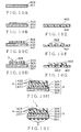
- the EL light source 3 is made as follows:
- an alternating voltage is applied from an alternating-current source to between the transparent electrode 302 and the back surface electrode 305, thereby the light-emitting layer 303 emits the light so that the dial 2 formed on the front surface-side can be illuminated from the back surface-side.
- the EL light source 3 on which the dial 2 is applied and the FPC 4 are formed in one piece, thereby the module 1 is constructed as a flexible sheet as a whole. Therefore, the number of components can be reduced so that the assembling work of the meter employing such a dial module can be facilitated, thereby enabling the improvement in productivity and reduce in cost.
- the dial module may be constructed in such a manner that a dial having meter design parts is formed on a front surface of a sheet-shaped EL light source 3 by printing and a FPC 4 is formed on a back surface of the EL light source 3 by printing.
- an alternating voltage is applied to between the transparent electrode 302 and the back surface electrode 305, thereby the light-emitting layer 303 emits the light so that the dial 2 formed on the front surface-side can be illuminated from the back surface-side.
- the dial 2 is formed on the surface-side and the FPC 4 is formed on the back surface-side, thereby the module 1 is constructed as a flexible sheet as a whole. Therefore, the number of components can be further reduced so that the assembling work of the meter employing such a dial module can be facilitated, thereby enabling the improvement in productivity and reduce in cost.
- the dial module may be constructed in such a manner that a sheet-shaped EL light source 3 having a FPC 4 on the back surface thereof is fixed to a back surface of a sheet-shaped dial 2 having meter design parts on a surface thereof by fixing means such as an adhesive so that the emission from the EL light source 3 illuminates the meter design parts of the dial 2.
- the dial 2 and the EL light source 3 can be formed in substantially the same shape.
- the sheet-shaped dial 2 and the sheet-shaped EL light source 3 having the FPC 4 on the back surface thereof are formed in one piece, thereby the module 1 is constructed as a flexible sheet as a whole. Therefore, the number of components can be reduced so that the assembling work of the meter employing such a dial module can be facilitated, thereby enabling the improvement in productivity and reduce in cost and enabling to meet with the demand of a plurality of types of vehicle in common.
- the EL light source 3 in the present invention either of organic and inorganic EL light sources can be employed.
- the number of components can be reduced so that the assembling work of the meter employing such a dial module can be facilitated, thereby enabling the improvement in productivity and reduce in cost.
- the dial module has a flexible sheet-shaped form, it can be applied not only when all of a plurality of meters constructed by the dial has a flat design but also even when a part of a plurality of meters constructed by the dial has a design including some unevenness, thereby improving in the design and enabling to meet with the demand of a plurality of types of vehicle in common.
- the manufacturing can be easy.
- the number of components can be further reduced so that the assembling work of the meter employing such a dial module can be facilitated, thereby enabling the improvement in productivity and reduce in cost. It is possible to meet with the demand of a plurality of types of vehicle in common.
- the dial module can be realized by employing a sheet-shaped electroluminescent light source as the sheet-shaped light source.
- the dial module With the invention defined in claim 10, it is possible to easily manufacture the dial module, with which the sheet-shaped light source having the dial and the flexible printed circuit for carrying out the function of the dial are integrally formed.
- the dial module including the dial and the sheet-shaped light source having the function of the flexible printed circuit for carrying out the function of the dial.
- the dial module can be realized by employing a sheet-shaped electroluminescent light source as the sheet-shaped light source.
- the number of components can be reduced so that the assembling work of the meter can be facilitated, thereby enabling the improvement in productivity and reduce in cost. It is possible to meet with the demand of a plurality of types of vehicle in common.
- a space for attaching the light-emitting diode can be reduced since the space can be set to be only its thickness due to the construction of the reflection-type light-emitting diode.
- the number of components can be reduced so that the assembling work of the meter can be facilitated, thereby enabling the improvement in productivity and reduce in cost. It is possible to meet with the demand of a plurality of types of vehicle in common.
- the number of components can be reduced so that the assembling work of the meter employing such a display module can be facilitated, thereby enabling the improvement in productivity and reduce in cost. It is possible to meet with the demand of a plurality of types of vehicle in common.
- the display module can be realized by employing a liquid crystal display.
- the number of components can be reduced so that the assembling work of the meter can be facilitated, thereby enabling the improvement in productivity and reduce in cost. It is possible to meet with the demand of a plurality of types of vehicle in common.
- the number of components can be reduced so that the assembling work of the meter employing such a movement module can be facilitated, thereby enabling the improvement in productivity and reduce in cost. It is possible to meet with the demand of a plurality of types of vehicle in common.
- the number of components can be reduced so that the assembling work of the meter can be facilitated, thereby enabling the improvement in productivity and reduce in cost. It is possible to meet with the demand of a plurality of types of vehicle in common.
- the number of components can be reduced so that the assembling work of the meter employing such a movement module can be facilitated, thereby enabling the improvement in productivity and reduce in cost. It is possible to meet with the demand of a plurality of types of vehicle in common. Further, it is possible to meet easily a change in the specification.
- the number of components can be reduced so that the assembling work of the meter can be facilitated, thereby enabling the improvement in productivity and reduce in cost. It is possible to meet with the demand of a plurality of types of vehicle in common.
Landscapes
- Engineering & Computer Science (AREA)
- Mechanical Engineering (AREA)
- Chemical & Material Sciences (AREA)
- Combustion & Propulsion (AREA)
- Transportation (AREA)
- General Physics & Mathematics (AREA)
- Physics & Mathematics (AREA)
- Instrument Panels (AREA)
- Details Of Measuring Devices (AREA)
- Devices For Indicating Variable Information By Combining Individual Elements (AREA)
- Coupling Device And Connection With Printed Circuit (AREA)
- Details Of Connecting Devices For Male And Female Coupling (AREA)
- Liquid Crystal (AREA)
- Led Device Packages (AREA)
- Electromechanical Clocks (AREA)
- Measuring Volume Flow (AREA)
- Electroluminescent Light Sources (AREA)
Abstract
Description
In order to attain the above objective, a dial module defined in
Claims (27)
- A dial module comprising:a sheet-shaped dial having a design part on a front surface of the dial;a sheet-shaped light source fixed to a back surface of the dial for illuminating the design part; anda flexible printed circuit fixed to a back surface of the light source.
- The dial module according to claim 1, wherein the dial, light source and flexible printed circuit are formed in substantially the same shape.
- A dial module comprising:wherein the dial is formed on a front surface of the light source.a dial having a design part;a sheet-shaped light source for illuminating the design part; anda flexible printed circuit fixed to a back surface of the light source,
- The dial module according to claim 3, wherein the light source and flexible printed circuit are formed in substantially the same shape.
- A dial module comprising:wherein the light source is provided with a flexible printed circuit on a back surface of the light source.a sheet-shaped dial having a design part on a front surface of the dial; anda sheet-shaped light source fixed to a back surface of the dial for illuminating the design part,
- The dial module according to claim 5, wherein the dial and light source are formed in substantially the same shape.
- A dial module comprising a sheet-shaped light source, wherein a dial having a design part is formed on a front surface of the light source while a flexible printed circuit is formed on a back surface of the light source.
- The dial module as claimed in any one of claims 1 - 7, further comprising a connecting terminal part for attaching an additional component thereto.
- The dial module as claimed in any one of claims 1 - 8, wherein the light source is a sheet-shaped electroluminescent light source.
- A process for manufacturing a dial module comprising:a first step in which a flexible printed circuit is put and sealed on a back surface of a sheet-shaped light source with an adhesive; anda second step in which a dial having a design part is printed on a front surface of the light source.
- The process for manufacturing a dial module according to claim 10, wherein the light source is formed by providing a transparent electrically conductive film with a luminous layer, insulating layer and back surface electrode, and the flexible printed circuit is formed by providing a copper foil film with a circuit with etching followed by an insulation processing.
- A process for manufacturing a dial module comprising:a first step in which a circuit is formed on a back surface of a sheet-shaped light source by printing an electrically conductive material on the back surface; anda second step in which a dial having a design part is printed on a front surface of the light source.
- The process for manufacturing a dial module according to claim 12, further comprising a third step in which an insulation processing is applied on a part where the circuit is formed.
- The process for manufacturing a dial module as claimed in any one of claims 10 - 13, wherein the light source is a sheet-shaped electroluminescent light source.
- A meter comprising:the dial module as claimed in any one of claims 1 - 9;a frame board arranged in front of the dial of the dial module;a front glass arranged in front of the frame board; anda casing arranged in the rear of the dial module for fixing the dial module between the frame board and the casing.
- A light-emitting diode display element for supplying electric power to a light-emitting element, comprising a lead terminal for fixing the light-emitting element to an opposite attaching member situated in the same direction as that of emission from the light-emitting element.
- A light-emitting diode display element comprising:a light-emitting element;an optically transparent member for sealing the light-emitting element, the optically transparent member including a reflecting surface on the side of emission of the light-emitting element and an emitting surface in the rear of the light-emitting element;a reflecting mirror provided on the reflecting surface, for reflecting the emission from the light-emitting element and guiding out the emission from the emitting surface; anda lead terminal connected to the light-emitting element, the lead terminal protruding from a side of the optically transparent member and including an end substantially flush with the emitting surface.
- A meter comprising:the dial module as claimed in any one of claims 1 - 9;a first opening formed on a part of the sheet-shaped light source of the dial module;a second opening formed on a part of the flexible printed circuit of the dial module so as to be lined up with the first opening;the light-emitting diode display element according to claim 16 or 17, in which the lead terminal is connected to the flexible printed circuit and the emission from the light-emitting element is guided to the second opening;a design formed on the sheet-shaped dial and illuminated with the emission from the light-emitting element through the first and second openings;a frame board arranged in front of the dial of the dial module;a front glass arranged in front of the frame board; anda casing arranged in the rear of the dial module for fixing the dial module between the frame board and the casing.
- A display module comprising:a printed board;a display element mounted on the printed board;a driver element mounted on the printed board for driving the display element; anda connecting terminal formed on the printed board.
- The display module according to claim 19, wherein the display element is a liquid crystal display element.
- A meter comprising:the dial module as claimed in any one of claims 1 - 9;a first notch formed on a part of the sheet-shaped dial of the dial module;a second notch formed on a part of the sheet-shaped light source of the dial module so as to be lined up with the first notch;a display window formed on a part of the flexible printed circuit of the dial module so as to be situated in the rear of the first and second notches;the display module according to claim 19 or 20 mounted on the flexible printed circuit so as to be situated at the display window;a frame board arranged in front of the dial of the dial module;a front glass arranged in front of the frame board; anda casing arranged in the rear of the dial module for fixing the dial module between the frame board and the casing.
- A movement module comprising:a printed board;a stepper motor mounted on the printed board;a driver element mounted on the printed board for driving the stepper motor; anda connecting terminal formed on the printed board.
- A meter comprising:the dial module as claimed in any one of claims 1 - 9;the movement module according to claim 22 mounted on the flexible printed circuit of the dial module so as to be situated at the display window;a frame board arranged in front of the dial of the dial module;a front glass arranged in front of the frame board; anda casing arranged in the rear of the dial module for fixing the dial module between the frame board and the casing.
- A connector module comprising:a housing including first and second tube parts;a first connecting terminal penetrating through a bottom of the first tube part for connecting to an outside connector inside the first tube part, the first connecting terminal being mounted so that a part of the first connecting terminal is situated inside the first tube part while another part of the first connecting terminal is exposed to the outside of the first tube part;a second connecting terminal penetrating through a bottom of the second tube part, the second connecting terminal being mounted so that a part of the second connecting terminal is situated inside the second tube part while another part of the second connecting terminal is exposed to the outside of the second tube part; anda circuit board received in the second tube part, the circuit board being detachably connected to the second connecting terminal.
- The connector module according to claim 24, wherein the part of the second connecting terminal, which part is situated inside the second tube part, is a resilient contact.
- The connector module according to claim 24 or 25 further comprising a cover for closing an opening of the second tube part.
- A meter comprising:the dial module as claimed in any one of claims 1 - 9;the connector module as claimed in any one of claims 24 - 26, in which each of the other parts of the first and second connecting terminals exposed to the outside of the tube part is connected to the flexible printed circuit of the dial module;a frame board arranged in front of the dial of the dial module;a front glass arranged in front of the frame board; anda casing arranged in the rear of the dial module for fixing the dial module between the frame board and the casing.
Priority Applications (3)
| Application Number | Priority Date | Filing Date | Title |
|---|---|---|---|
| EP09167471.3A EP2116816B1 (en) | 2002-09-20 | 2003-09-19 | Movement module and meter employing the same |
| EP09167472.1A EP2116817B1 (en) | 2002-09-20 | 2003-09-19 | Connector module and meter employing the same |
| EP09167481.2A EP2113749B1 (en) | 2002-09-20 | 2003-09-19 | Display module and meter employing the same |
Applications Claiming Priority (3)
| Application Number | Priority Date | Filing Date | Title |
|---|---|---|---|
| JP2002275896 | 2002-09-20 | ||
| JP2002275896 | 2002-09-20 | ||
| PCT/JP2003/012013 WO2004033999A1 (en) | 2002-09-20 | 2003-09-19 | Dial module, manufacturing method thereof, led display element, display module, movement module, connector module, and meter using them |
Related Child Applications (6)
| Application Number | Title | Priority Date | Filing Date |
|---|---|---|---|
| EP09167471.3A Division EP2116816B1 (en) | 2002-09-20 | 2003-09-19 | Movement module and meter employing the same |
| EP09167472.1A Division EP2116817B1 (en) | 2002-09-20 | 2003-09-19 | Connector module and meter employing the same |
| EP09167481.2A Division EP2113749B1 (en) | 2002-09-20 | 2003-09-19 | Display module and meter employing the same |
| EP09167471.3 Division-Into | 2009-08-07 | ||
| EP09167472.1 Division-Into | 2009-08-07 | ||
| EP09167481.2 Division-Into | 2009-08-07 |
Publications (3)
| Publication Number | Publication Date |
|---|---|
| EP1541972A1 true EP1541972A1 (en) | 2005-06-15 |
| EP1541972A4 EP1541972A4 (en) | 2009-05-27 |
| EP1541972B1 EP1541972B1 (en) | 2013-02-20 |
Family
ID=32089129
Family Applications (4)
| Application Number | Title | Priority Date | Filing Date |
|---|---|---|---|
| EP09167472.1A Expired - Lifetime EP2116817B1 (en) | 2002-09-20 | 2003-09-19 | Connector module and meter employing the same |
| EP03751277A Expired - Lifetime EP1541972B1 (en) | 2002-09-20 | 2003-09-19 | Dial module and manufacturing method thereof |
| EP09167471.3A Expired - Lifetime EP2116816B1 (en) | 2002-09-20 | 2003-09-19 | Movement module and meter employing the same |
| EP09167481.2A Expired - Lifetime EP2113749B1 (en) | 2002-09-20 | 2003-09-19 | Display module and meter employing the same |
Family Applications Before (1)
| Application Number | Title | Priority Date | Filing Date |
|---|---|---|---|
| EP09167472.1A Expired - Lifetime EP2116817B1 (en) | 2002-09-20 | 2003-09-19 | Connector module and meter employing the same |
Family Applications After (2)
| Application Number | Title | Priority Date | Filing Date |
|---|---|---|---|
| EP09167471.3A Expired - Lifetime EP2116816B1 (en) | 2002-09-20 | 2003-09-19 | Movement module and meter employing the same |
| EP09167481.2A Expired - Lifetime EP2113749B1 (en) | 2002-09-20 | 2003-09-19 | Display module and meter employing the same |
Country Status (7)
| Country | Link |
|---|---|
| US (3) | US20060044778A1 (en) |
| EP (4) | EP2116817B1 (en) |
| JP (5) | JP4414706B2 (en) |
| KR (4) | KR100899345B1 (en) |
| CN (4) | CN101685028B (en) |
| ES (3) | ES2425845T3 (en) |
| WO (1) | WO2004033999A1 (en) |
Cited By (2)
| Publication number | Priority date | Publication date | Assignee | Title |
|---|---|---|---|---|
| WO2008006593A1 (en) * | 2006-07-14 | 2008-01-17 | Johnson Controls Automotive Electronics Gmbh | Display device for a motor vehicle, comprising a substantially parallel light beam |
| CN113895225A (en) * | 2020-07-06 | 2022-01-07 | 矢崎总业株式会社 | Meter device for vehicle |
Families Citing this family (32)
| Publication number | Priority date | Publication date | Assignee | Title |
|---|---|---|---|---|
| US7347575B2 (en) * | 2004-07-13 | 2008-03-25 | Yazaki North America, Inc. | Vehicle gauge with embedded driver information |
| JP4583889B2 (en) * | 2004-11-12 | 2010-11-17 | 矢崎総業株式会社 | Instrument device |
| US7562993B2 (en) * | 2005-08-10 | 2009-07-21 | Denso International America, Inc. | Continuous LED instrument panel |
| US20070245821A1 (en) * | 2006-04-11 | 2007-10-25 | Ching-Su Chiu | Luminescent refrigerant gauge device |
| JP5189268B2 (en) * | 2006-10-19 | 2013-04-24 | 矢崎総業株式会社 | Vehicle display device |
| JP4851385B2 (en) * | 2007-04-26 | 2012-01-11 | 株式会社デンソー | Vehicle display device |
| US8305769B2 (en) * | 2008-11-20 | 2012-11-06 | Interplex Industries, Inc. | Solderless electronic component or capacitor mount assembly |
| KR101293815B1 (en) * | 2008-12-12 | 2013-08-06 | 후루카와 덴키 고교 가부시키가이샤 | Internally illuminated display and display panel therefor |
| JP5549120B2 (en) * | 2009-06-08 | 2014-07-16 | 株式会社日立製作所 | Power conversion device for railway vehicles |
| KR101422362B1 (en) * | 2009-07-10 | 2014-07-22 | 가부시키가이샤 한도오따이 에네루기 켄큐쇼 | Display device, display panel and electronic appliance |
| FR2948470B1 (en) * | 2009-07-21 | 2011-09-16 | Valeo Systemes Thermiques | METHOD FOR MANUFACTURING A MAN / MACHINE INTERFACE FOR A MOTOR VEHICLE AND MAN / MACHINE INTERFACE FOR THIS METHOD |
| JP5493831B2 (en) * | 2009-12-25 | 2014-05-14 | 日本精機株式会社 | Instrument device |
| US8441801B2 (en) * | 2010-04-27 | 2013-05-14 | Electrolux Home Products, Inc. | Flexible mount system |
| JP5636840B2 (en) * | 2010-09-24 | 2014-12-10 | 株式会社バッファロー | Electronics |
| KR101783955B1 (en) * | 2011-02-10 | 2017-10-11 | 삼성디스플레이 주식회사 | Light emitting diode package and back light unit having the same |
| CN103687743B (en) * | 2011-05-13 | 2016-11-09 | 大众汽车有限公司 | Display unit for vehicle |
| US9902265B2 (en) | 2011-05-13 | 2018-02-27 | Volkswagen Ag | Display device for a vehicle, and vehicle |
| US8460030B2 (en) * | 2011-06-21 | 2013-06-11 | Nai-Chien Chang | Connector with detachable module |
| CN102955270A (en) * | 2011-08-30 | 2013-03-06 | 昆山顺景光电有限公司 | COG (chip on glass) liquid crystal display module with Chinese character library |
| TWM442601U (en) * | 2012-04-26 | 2012-12-01 | Nai-Chien Chang | The wireless module and using the wireless module connector |
| CN102923001A (en) * | 2012-10-31 | 2013-02-13 | 埃泰克汽车电子(芜湖)有限公司 | Automobile instrument structure |
| CN104952367B (en) * | 2015-07-07 | 2017-12-08 | 珠海格力电器股份有限公司 | Display module and electric appliance with same |
| JP6406235B2 (en) | 2015-12-16 | 2018-10-17 | オムロン株式会社 | Electronic device and manufacturing method thereof |
| CN107403592A (en) * | 2017-06-16 | 2017-11-28 | 重庆天盛仪表有限公司 | Instrument with drive circuit LED digital screens |
| JP2019045209A (en) * | 2017-08-30 | 2019-03-22 | 日本精機株式会社 | Display device |
| EP3700369B1 (en) * | 2017-10-24 | 2022-08-03 | Philip Morris Products S.A. | Aerosol-generating device having holding mechanism |
| JP6652544B2 (en) * | 2017-11-27 | 2020-02-26 | 矢崎総業株式会社 | Meter device and meter unit having the same |
| CN111416230A (en) * | 2020-01-21 | 2020-07-14 | 东莞立讯技术有限公司 | Fan connector |
| US11381045B2 (en) * | 2020-01-21 | 2022-07-05 | Dongguan Luxshare Technologies Co., Ltd | Fan connector |
| KR20220114831A (en) | 2021-02-09 | 2022-08-17 | 동서대학교 산학협력단 | Fish-shaped bread vending machine |
| US20230143094A1 (en) * | 2021-11-11 | 2023-05-11 | Preddio Technologies Inc. | Contact identification attachment for electrical connectors |
| US12334693B2 (en) * | 2022-12-01 | 2025-06-17 | GM Global Technology Operations LLC | Reconfigurable connector system |
Family Cites Families (72)
| Publication number | Priority date | Publication date | Assignee | Title |
|---|---|---|---|---|
| US3475657A (en) * | 1967-01-03 | 1969-10-28 | Litton Systems Inc | Mounting of electronic components on baseboard or panel |
| JPS583696B2 (en) | 1976-07-16 | 1983-01-22 | オリンパス光学工業株式会社 | Pressing and fixing device for endoscope film cassette |
| JPS53105776U (en) * | 1977-01-29 | 1978-08-25 | ||
| JPS6029832Y2 (en) * | 1980-06-13 | 1985-09-07 | 日本電気株式会社 | male connector |
| JPS62172220A (en) | 1986-01-25 | 1987-07-29 | Nissan Motor Co Ltd | Illumination structure of display panel of indicating instrument |
| US4774434A (en) * | 1986-08-13 | 1988-09-27 | Innovative Products, Inc. | Lighted display including led's mounted on a flexible circuit board |
| JPH01205480A (en) * | 1988-02-12 | 1989-08-17 | Iwasaki Electric Co Ltd | Light emitting diode and led surface light emission source |
| US4775964A (en) * | 1988-01-11 | 1988-10-04 | Timex Corporation | Electroluminescent dial for an analog watch and process for making it |
| US4963098A (en) * | 1988-02-26 | 1990-10-16 | Amp Incorporated | Blind mate shielded input/output connector assembly |
| JPH02222583A (en) * | 1989-02-23 | 1990-09-05 | Mitsubishi Electric Corp | Mounting and check of light emitting element |
| JPH0368017A (en) * | 1989-08-08 | 1991-03-25 | Fujitsu Ltd | Error processor |
| JP2516117Y2 (en) * | 1990-09-28 | 1996-11-06 | 日本電気株式会社 | Connector for PCB edge mounting |
| JPH0831621B2 (en) * | 1990-11-06 | 1996-03-27 | 岩崎電気株式会社 | Light emitting diode array |
| US5085601A (en) * | 1990-12-11 | 1992-02-04 | Amp Incorporated | Reduced insertion force electrical connector |
| JPH06511212A (en) * | 1991-05-09 | 1994-12-15 | ヌ−テック アンド エンジニアリング インコーポレイテッド | Instrument display methods and systems for passenger cars |
| JPH0528737A (en) | 1991-07-25 | 1993-02-05 | Nec Ibaraki Ltd | Magnetic disk device |
| JP3237136B2 (en) | 1991-08-08 | 2001-12-10 | 株式会社デンソー | Vehicle air conditioner |
| JP2593775Y2 (en) * | 1991-08-10 | 1999-04-12 | 古河電気工業株式会社 | Module box for mounting the instrument panel |
| JPH0538927U (en) * | 1991-10-24 | 1993-05-25 | 日本ビクター株式会社 | Light emitting device |
| JPH05129661A (en) * | 1991-10-31 | 1993-05-25 | Iwasaki Electric Co Ltd | Light emitting diode lamp |
| JP2567478Y2 (en) * | 1992-07-14 | 1998-04-02 | 矢崎総業株式会社 | Flexible mounting structure of meter case |
| JPH06138536A (en) * | 1992-10-28 | 1994-05-20 | Fuji Photo Film Co Ltd | Information recorder for camera |
| DE69332780T2 (en) * | 1992-12-16 | 2004-03-04 | Durel Corp., Tempe | ELECTROLUMINESCENT LAMP DEVICES AND THEIR PRODUCTION |
| US5265071A (en) * | 1993-02-02 | 1993-11-23 | Timex Corporation | Electroluminescent watch dial support and connector assembly |
| JPH06249679A (en) * | 1993-02-26 | 1994-09-09 | Nippon Seiki Co Ltd | Pointer illuminating device |
| US5399105A (en) * | 1994-04-29 | 1995-03-21 | The Whitaker Corporation | Conductive shroud for electrical connectors |
| JPH0832106A (en) * | 1994-07-14 | 1996-02-02 | Toshiba Electron Eng Corp | Optical semiconductor device and substrate mounting device |
| JPH0832119A (en) * | 1994-07-15 | 1996-02-02 | Canon Inc | Printed wiring board |
| JPH10510920A (en) * | 1994-12-20 | 1998-10-20 | ローベルト ボツシユ ゲゼルシヤフト ミツト ベシユレンクテル ハフツング | Display instrument |
| JPH08201102A (en) * | 1995-01-31 | 1996-08-09 | Yazaki Corp | Distance totalizer unit |
| JPH08230516A (en) * | 1995-02-23 | 1996-09-10 | Yazaki Corp | Combination meter |
| JPH0992415A (en) * | 1995-09-22 | 1997-04-04 | Sumitomo Wiring Syst Ltd | Card edge connector |
| JP3136395B2 (en) * | 1995-09-29 | 2001-02-19 | 株式会社デンソー | Transmitted illumination type indicator |
| JP3156836B2 (en) * | 1995-12-07 | 2001-04-16 | 矢崎総業株式会社 | Pointer display |
| JP3246359B2 (en) * | 1996-11-11 | 2002-01-15 | 株式会社デンソー | Display device |
| JPH10150225A (en) * | 1996-11-19 | 1998-06-02 | Iwasaki Electric Co Ltd | Self-luminous pointer using reflective light emitting diode |
| JPH10185627A (en) | 1996-12-25 | 1998-07-14 | Nippon Seiki Co Ltd | Instrument lighting device |
| JP3311640B2 (en) * | 1996-12-26 | 2002-08-05 | 矢崎総業株式会社 | Waterproof structure of electric wire outlet |
| US5947753A (en) * | 1997-01-13 | 1999-09-07 | Amphenol Corporation | High density connector arrangement for a circuit board module |
| JPH10300527A (en) * | 1997-04-25 | 1998-11-13 | Nippon Seiki Co Ltd | El illumination type measuring instrument |
| JP3638787B2 (en) * | 1997-04-28 | 2005-04-13 | 矢崎総業株式会社 | Center cluster module system |
| JP3457148B2 (en) * | 1997-06-18 | 2003-10-14 | 矢崎総業株式会社 | Combination meter |
| DE19737787B4 (en) * | 1997-08-29 | 2006-05-24 | Robert Bosch Gmbh | display |
| GB2334807A (en) * | 1998-02-27 | 1999-09-01 | Nokia Mobile Phones Ltd | Display assembly |
| JP2000124479A (en) * | 1998-10-16 | 2000-04-28 | Sanyo Electric Co Ltd | Optical semiconductor device |
| JP2000165062A (en) * | 1998-11-30 | 2000-06-16 | Toshiba Corp | Circuit module and electronic device provided with circuit module |
| US6106127A (en) * | 1999-03-19 | 2000-08-22 | Luminary Logic Ltd. | Illuminating device for watches, gauges and similar devices |
| US6183099B1 (en) * | 1999-06-09 | 2001-02-06 | Timex Corporation | Light guide for illuminating a dial |
| JP4258896B2 (en) * | 1999-07-14 | 2009-04-30 | 株式会社デンソー | Compound display device |
| JP4330716B2 (en) * | 1999-08-04 | 2009-09-16 | 浜松ホトニクス株式会社 | Floodlight device |
| JP4292647B2 (en) * | 1999-09-16 | 2009-07-08 | 株式会社デンソー | Compound display device |
| WO2001033641A1 (en) * | 1999-11-01 | 2001-05-10 | Rohm Co., Ltd. | Semiconductor light-emitting device |
| DE19956542A1 (en) * | 1999-11-24 | 2001-05-31 | Mannesmann Vdo Ag | Display instrument for vehicle with LED and light conductive indicator fixedly connected to indicator shaft formed as light conductor |
| JP4224924B2 (en) * | 2000-03-30 | 2009-02-18 | 株式会社デンソー | Manufacturing method of indicating instrument |
| JP3530460B2 (en) * | 2000-04-27 | 2004-05-24 | 山一電機株式会社 | Card connector |
| JP2001313128A (en) * | 2000-04-27 | 2001-11-09 | Yamaichi Electronics Co Ltd | Card connector |
| DE10021099A1 (en) * | 2000-05-02 | 2001-11-15 | Bosch Gmbh Robert | Lighting and display device |
| JP2002044830A (en) * | 2000-07-24 | 2002-02-08 | Auto Network Gijutsu Kenkyusho:Kk | VEHICLE DISTRIBUTOR AND METHOD OF CONNECTING CONTROL CIRCUIT BOARD TO VEHICLE DISTRIBUTOR |
| CN2436353Y (en) * | 2000-08-27 | 2001-06-27 | 大连理工大学 | Instrument and meter for vehicle |
| JP2002071394A (en) * | 2000-09-01 | 2002-03-08 | Denso Corp | Vehicle instrument |
| JP2002223005A (en) * | 2001-01-26 | 2002-08-09 | Toyoda Gosei Co Ltd | Light emitting diode and display device |
| TW483599U (en) * | 2001-05-11 | 2002-04-11 | Quanta Comp Inc | Client ID connector with two ID slot |
| US6600865B2 (en) * | 2001-06-21 | 2003-07-29 | Hon Hai Precision Ind. Co., Ltd. | Stacked GBIC guide rail assembly |
| JP2003162242A (en) * | 2001-11-29 | 2003-06-06 | Casio Comput Co Ltd | Light emitting device and electronic equipment |
| JP2003240611A (en) * | 2002-02-21 | 2003-08-27 | Nippon Seiki Co Ltd | Instrument device |
| JP4237535B2 (en) * | 2003-04-24 | 2009-03-11 | 山一電機株式会社 | Interface device |
| US7070446B2 (en) * | 2003-08-27 | 2006-07-04 | Tyco Electronics Corporation | Stacked SFP connector and cage assembly |
| US6857907B1 (en) * | 2003-11-25 | 2005-02-22 | Data Fab Systems, Inc. | Electrical connector adapted for use with first and second electronic cards |
| US7083468B2 (en) * | 2004-05-11 | 2006-08-01 | Hon Hai Precision Ind. Co., Ltd. | Stacked electrical connector assembly |
| CN105093391B (en) * | 2004-05-14 | 2022-12-02 | 莫莱克斯公司 | Light pipe assembly and connector assembly |
| TWM266493U (en) * | 2004-10-26 | 2005-06-01 | Carry Computer Eng Co Ltd | Data access device for memory card |
| KR100935778B1 (en) * | 2006-08-03 | 2010-01-06 | 니혼 고꾸 덴시 고교 가부시끼가이샤 | Easily Adapted Connectors for Miniaturization |
-
2003
- 2003-09-19 CN CN2009101453296A patent/CN101685028B/en not_active Expired - Fee Related
- 2003-09-19 WO PCT/JP2003/012013 patent/WO2004033999A1/en not_active Ceased
- 2003-09-19 EP EP09167472.1A patent/EP2116817B1/en not_active Expired - Lifetime
- 2003-09-19 ES ES09167481T patent/ES2425845T3/en not_active Expired - Lifetime
- 2003-09-19 CN CN2009101453281A patent/CN101685027B/en not_active Expired - Fee Related
- 2003-09-19 CN CNB2007101011520A patent/CN100507982C/en not_active Expired - Fee Related
- 2003-09-19 KR KR1020057004692A patent/KR100899345B1/en not_active Expired - Fee Related
- 2003-09-19 ES ES09167471T patent/ES2423286T3/en not_active Expired - Lifetime
- 2003-09-19 JP JP2003328121A patent/JP4414706B2/en not_active Expired - Fee Related
- 2003-09-19 KR KR1020097000592A patent/KR100905735B1/en not_active Expired - Fee Related
- 2003-09-19 ES ES09167472T patent/ES2423310T3/en not_active Expired - Lifetime
- 2003-09-19 CN CNB038244241A patent/CN1318823C/en not_active Expired - Fee Related
- 2003-09-19 EP EP03751277A patent/EP1541972B1/en not_active Expired - Lifetime
- 2003-09-19 KR KR1020067024283A patent/KR100933973B1/en not_active Expired - Fee Related
- 2003-09-19 KR KR1020097005956A patent/KR100933972B1/en not_active Expired - Fee Related
- 2003-09-19 EP EP09167471.3A patent/EP2116816B1/en not_active Expired - Lifetime
- 2003-09-19 EP EP09167481.2A patent/EP2113749B1/en not_active Expired - Lifetime
- 2003-09-19 US US10/528,448 patent/US20060044778A1/en not_active Abandoned
- 2003-12-19 JP JP2003422609A patent/JP2004206120A/en active Pending
- 2003-12-19 JP JP2003422610A patent/JP4414749B2/en not_active Expired - Fee Related
- 2003-12-19 JP JP2003422608A patent/JP2004200704A/en active Pending
- 2003-12-19 JP JP2003422611A patent/JP4095954B2/en not_active Expired - Fee Related
-
2008
- 2008-07-31 US US12/219,993 patent/US7699624B2/en not_active Expired - Fee Related
- 2008-07-31 US US12/219,975 patent/US7952274B2/en not_active Expired - Fee Related
Cited By (6)
| Publication number | Priority date | Publication date | Assignee | Title |
|---|---|---|---|---|
| WO2008006593A1 (en) * | 2006-07-14 | 2008-01-17 | Johnson Controls Automotive Electronics Gmbh | Display device for a motor vehicle, comprising a substantially parallel light beam |
| US8172439B2 (en) | 2006-07-14 | 2012-05-08 | Johnson Controls Automotive Electronics Gmbh | Display device for a motor vehicle, comprising a substantially parallel light beam |
| CN113895225A (en) * | 2020-07-06 | 2022-01-07 | 矢崎总业株式会社 | Meter device for vehicle |
| EP3936364A1 (en) * | 2020-07-06 | 2022-01-12 | Yazaki Corporation | Instrument device for a vehicle |
| US11752868B2 (en) | 2020-07-06 | 2023-09-12 | Yazaki Corporation | Instrument device for a vehicle |
| CN113895225B (en) * | 2020-07-06 | 2024-03-19 | 矢崎总业株式会社 | Instrumentation devices for vehicles |
Also Published As
Similar Documents
| Publication | Publication Date | Title |
|---|---|---|
| EP2113749B1 (en) | Display module and meter employing the same | |
| EP2699875B1 (en) | Motor for a rotatable and illuminable pointer | |
| CN113895225B (en) | Instrumentation devices for vehicles | |
| JP3350928B2 (en) | Instrument equipment | |
| EP1842713B1 (en) | A tachometer pointer instrument | |
| JP5189268B2 (en) | Vehicle display device | |
| JP2000304576A (en) | Instrument fixed structure | |
| JP2018080983A (en) | Instrument device |
Legal Events
| Date | Code | Title | Description |
|---|---|---|---|
| PUAI | Public reference made under article 153(3) epc to a published international application that has entered the european phase |
Free format text: ORIGINAL CODE: 0009012 |
|
| 17P | Request for examination filed |
Effective date: 20050318 |
|
| AK | Designated contracting states |
Kind code of ref document: A1 Designated state(s): AT BE BG CH CY CZ DE DK EE ES FI FR GB GR HU IE IT LI LU MC NL PT RO SE SI SK TR |
|
| RBV | Designated contracting states (corrected) |
Designated state(s): DE ES FR GB |
|
| RAP1 | Party data changed (applicant data changed or rights of an application transferred) |
Owner name: YAZAKI CORPORATION |
|
| A4 | Supplementary search report drawn up and despatched |
Effective date: 20090428 |
|
| 17Q | First examination report despatched |
Effective date: 20111111 |
|
| GRAP | Despatch of communication of intention to grant a patent |
Free format text: ORIGINAL CODE: EPIDOSNIGR1 |
|
| GRAS | Grant fee paid |
Free format text: ORIGINAL CODE: EPIDOSNIGR3 |
|
| GRAA | (expected) grant |
Free format text: ORIGINAL CODE: 0009210 |
|
| AK | Designated contracting states |
Kind code of ref document: B1 Designated state(s): DE ES FR GB |
|
| REG | Reference to a national code |
Ref country code: GB Ref legal event code: FG4D |
|
| REG | Reference to a national code |
Ref country code: DE Ref legal event code: R096 Ref document number: 60343318 Country of ref document: DE Effective date: 20130418 |
|
| PG25 | Lapsed in a contracting state [announced via postgrant information from national office to epo] |
Ref country code: ES Free format text: LAPSE BECAUSE OF FAILURE TO SUBMIT A TRANSLATION OF THE DESCRIPTION OR TO PAY THE FEE WITHIN THE PRESCRIBED TIME-LIMIT Effective date: 20130531 |
|
| PLBE | No opposition filed within time limit |
Free format text: ORIGINAL CODE: 0009261 |
|
| STAA | Information on the status of an ep patent application or granted ep patent |
Free format text: STATUS: NO OPPOSITION FILED WITHIN TIME LIMIT |
|
| 26N | No opposition filed |
Effective date: 20131121 |
|
| REG | Reference to a national code |
Ref country code: DE Ref legal event code: R097 Ref document number: 60343318 Country of ref document: DE Effective date: 20131121 |
|
| GBPC | Gb: european patent ceased through non-payment of renewal fee |
Effective date: 20130919 |
|
| PG25 | Lapsed in a contracting state [announced via postgrant information from national office to epo] |
Ref country code: GB Free format text: LAPSE BECAUSE OF NON-PAYMENT OF DUE FEES Effective date: 20130919 |
|
| REG | Reference to a national code |
Ref country code: FR Ref legal event code: PLFP Year of fee payment: 14 |
|
| REG | Reference to a national code |
Ref country code: FR Ref legal event code: PLFP Year of fee payment: 15 |
|
| PGFP | Annual fee paid to national office [announced via postgrant information from national office to epo] |
Ref country code: DE Payment date: 20170912 Year of fee payment: 15 Ref country code: FR Payment date: 20170810 Year of fee payment: 15 |
|
| REG | Reference to a national code |
Ref country code: DE Ref legal event code: R119 Ref document number: 60343318 Country of ref document: DE |
|
| PG25 | Lapsed in a contracting state [announced via postgrant information from national office to epo] |
Ref country code: DE Free format text: LAPSE BECAUSE OF NON-PAYMENT OF DUE FEES Effective date: 20190402 |
|
| PG25 | Lapsed in a contracting state [announced via postgrant information from national office to epo] |
Ref country code: FR Free format text: LAPSE BECAUSE OF NON-PAYMENT OF DUE FEES Effective date: 20180930 |