EP3700369B1 - Aerosol-generating device having holding mechanism - Google Patents
Aerosol-generating device having holding mechanism Download PDFInfo
- Publication number
- EP3700369B1 EP3700369B1 EP18789674.1A EP18789674A EP3700369B1 EP 3700369 B1 EP3700369 B1 EP 3700369B1 EP 18789674 A EP18789674 A EP 18789674A EP 3700369 B1 EP3700369 B1 EP 3700369B1
- Authority
- EP
- European Patent Office
- Prior art keywords
- aerosol
- holding member
- chamber
- opening
- article
- Prior art date
- Legal status (The legal status is an assumption and is not a legal conclusion. Google has not performed a legal analysis and makes no representation as to the accuracy of the status listed.)
- Active
Links
- 238000010438 heat treatment Methods 0.000 claims description 48
- 230000004913 activation Effects 0.000 claims description 4
- 239000000758 substrate Substances 0.000 description 11
- 239000000443 aerosol Substances 0.000 description 9
- 238000001994 activation Methods 0.000 description 3
- 238000005485 electric heating Methods 0.000 description 3
- 238000000605 extraction Methods 0.000 description 3
- 239000000463 material Substances 0.000 description 3
- 241000208125 Nicotiana Species 0.000 description 2
- 235000002637 Nicotiana tabacum Nutrition 0.000 description 2
- 230000000295 complement effect Effects 0.000 description 2
- 239000000356 contaminant Substances 0.000 description 2
- 230000009977 dual effect Effects 0.000 description 2
- 238000003780 insertion Methods 0.000 description 2
- 230000037431 insertion Effects 0.000 description 2
- HBBGRARXTFLTSG-UHFFFAOYSA-N Lithium ion Chemical compound [Li+] HBBGRARXTFLTSG-UHFFFAOYSA-N 0.000 description 1
- 239000004642 Polyimide Substances 0.000 description 1
- 230000015572 biosynthetic process Effects 0.000 description 1
- 239000003990 capacitor Substances 0.000 description 1
- 239000004020 conductor Substances 0.000 description 1
- 230000001939 inductive effect Effects 0.000 description 1
- 229910001416 lithium ion Inorganic materials 0.000 description 1
- 229910052751 metal Inorganic materials 0.000 description 1
- 239000002184 metal Substances 0.000 description 1
- 238000000034 method Methods 0.000 description 1
- 229920001721 polyimide Polymers 0.000 description 1
Images


Classifications
-
- A—HUMAN NECESSITIES
- A24—TOBACCO; CIGARS; CIGARETTES; SIMULATED SMOKING DEVICES; SMOKERS' REQUISITES
- A24F—SMOKERS' REQUISITES; MATCH BOXES; SIMULATED SMOKING DEVICES
- A24F40/00—Electrically operated smoking devices; Component parts thereof; Manufacture thereof; Maintenance or testing thereof; Charging means specially adapted therefor
- A24F40/40—Constructional details, e.g. connection of cartridges and battery parts
- A24F40/46—Shape or structure of electric heating means
-
- A—HUMAN NECESSITIES
- A24—TOBACCO; CIGARS; CIGARETTES; SIMULATED SMOKING DEVICES; SMOKERS' REQUISITES
- A24F—SMOKERS' REQUISITES; MATCH BOXES; SIMULATED SMOKING DEVICES
- A24F40/00—Electrically operated smoking devices; Component parts thereof; Manufacture thereof; Maintenance or testing thereof; Charging means specially adapted therefor
- A24F40/40—Constructional details, e.g. connection of cartridges and battery parts
- A24F40/48—Fluid transfer means, e.g. pumps
- A24F40/485—Valves; Apertures
-
- A—HUMAN NECESSITIES
- A24—TOBACCO; CIGARS; CIGARETTES; SIMULATED SMOKING DEVICES; SMOKERS' REQUISITES
- A24F—SMOKERS' REQUISITES; MATCH BOXES; SIMULATED SMOKING DEVICES
- A24F40/00—Electrically operated smoking devices; Component parts thereof; Manufacture thereof; Maintenance or testing thereof; Charging means specially adapted therefor
- A24F40/50—Control or monitoring
- A24F40/51—Arrangement of sensors
-
- A—HUMAN NECESSITIES
- A24—TOBACCO; CIGARS; CIGARETTES; SIMULATED SMOKING DEVICES; SMOKERS' REQUISITES
- A24F—SMOKERS' REQUISITES; MATCH BOXES; SIMULATED SMOKING DEVICES
- A24F40/00—Electrically operated smoking devices; Component parts thereof; Manufacture thereof; Maintenance or testing thereof; Charging means specially adapted therefor
- A24F40/20—Devices using solid inhalable precursors
-
- A—HUMAN NECESSITIES
- A24—TOBACCO; CIGARS; CIGARETTES; SIMULATED SMOKING DEVICES; SMOKERS' REQUISITES
- A24F—SMOKERS' REQUISITES; MATCH BOXES; SIMULATED SMOKING DEVICES
- A24F40/00—Electrically operated smoking devices; Component parts thereof; Manufacture thereof; Maintenance or testing thereof; Charging means specially adapted therefor
- A24F40/50—Control or monitoring
Definitions
- the invention relates to an aerosol-generating device as defined in the present claim 1, wherein such a device may be configured to heat articles containing a supply of aerosol-forming substrate.
- said aerosol-generating device may form part of an aerosol-generating system, such as a handheld electrically operated aerosol-generating system.
- Articles in which an aerosol forming substrate, such as tobacco, is heated rather than combusted have been proposed in the art.
- Such articles are heated by an aerosol-generating device comprising a heater and a chamber, into which a portion of the article can be inserted.
- the aerosol-forming substrate portion of the article is inserted into the chamber, and heated to produce an aerosol.
- a mouth end portion of the article remains outside of the chamber, and a consumer can draw on this mouth end portion of the article to receive the aerosol.
- the chamber is typically an elongate cylinder, and substantially corresponds in size and shape to the size and shape of the aerosol-generating article with which the device is intended to be used.
- the device may comprise a heater in the form of a heater blade, which extends from the base of the chamber. When the article is inserted into the chamber the heater blade penetrates the article. In some devices, the heater blade may help to hold the article in place relative to the chamber. However, a heater blade may not always provide an appropriate means for holding the article in place, once it has been inserted into the chamber.
- the chamber of a device may be desirable for the chamber of a device to have a width that is greater than the width of the articles to be heated in the chamber, in order to facilitate insertion of articles into the chamber and extraction of articles from the chamber.
- EP 3 228 199 A2 concerns an aerosol-generating device having a chamber for receiving an aerosol-generating article through an opening in the top wall of the device.
- the article is heated by heating elements which are disposed within the chamber and extend along a length of a side wall of the chamber.
- Heater element is movable from the position shown in Figure 1 of EP 3 228 199 A2 , to the position shown in Figure 2 of EP 3 228 199 A2 , in order to snugly engage an article when the article is in the chamber. Movement of the heater element is initiated by pressing a button on a side wall of the device.
- a double spring mechanism is used to couple the button to the heating element, in a similar manner to a conventional pen lid and ink cartridge.
- GB 2 534 215 A concerns an aerosol-generating device having a heating chamber.
- a recess in a side wall of the device defines at least part of an opening in one end of the chamber.
- the top wall of the chamber has a hinged part which can move from an open position shown in Figure 2 of GB 2 534 215 A to a closed position shown in Figure 1 of GB 2 534 215 A , to form the heating chamber.
- Figure 8 of GB 2 534 215 A an aerosol generating article is inserted into the device before the hinged part is closed, and thus before the chamber is formed.
- an aerosol-generating device for heating an aerosol-generating article, the device comprises: a housing having an opening; a chamber disposed within the housing, and configured to receive at least a portion of the aerosol-generating article through the opening in the housing; a heater assembly disposed within the housing, and comprising a heating element configured to heat at least a portion of the chamber; and a holding mechanism comprising at least one holding member disposed at or proximate to the opening of the housing, the at least one holding member comprising a plurality of blades in an iris arrangement, each of said blades being configured to move between: a first position, in which the aerosol-generating article can be inserted into the chamber through the opening; and a second position, in which each blade has reduced the size of the opening relative to the size of the opening when the blades are in the first position.
- an article can be easily inserted into the chamber of the device (when the holding member is in the first position), and then securely held in place by the holding member after said insertion (when the holding member is in the second position).
- the holding member can engage with a portion of the article which is less likely to be subjected to high temperatures from the heating assembly, such as a mouth end portion of the article.
- a portion of the article which is less likely to be subjected to high temperatures from the heating assembly, such as a mouth end portion of the article.
- the mouth end portion may also be more resilient than the aerosol-forming portion of the article. This means that the mouth end portion of the article is less likely to be damaged by the holding member, than if the holding member were engaging with the aerosol-forming portion of the article.
- the arrangement of the present invention also enables the device to utilise heater arrangements other than heater blade arrangements, without substantial risk of the article moving within the chamber or falling out of the chamber, during use.
- the holding mechanism is separate from or not the same component as the heater assembly. That is, the object or objects which form the holding mechanism are not the same as the object or objects which form the heater assembly. In this way, the function and performance of the heater assembly can remain unaffected by whether or not the at least one holding member is disposed in its first position or second position.
- the heater assembly and holding mechanism are arranged such that when an aerosol-generating article is received within the chamber, the heater assembly is configured to heat a first portion of the aerosol-generating article (such as an aerosol-forming portion) and the holding mechanism is configured to hold a second portion of the aerosol-generating article (such as a mouth end portion).
- the heater assembly may be disposed within or around the chamber and longitudinally spaced from holding mechanism.
- the holding mechanism may be disposed at or proximate the opening at a first longitudinal position, and the heater assembly may be disposed within or around the chamber at a second longitudinal position, the second longitudinal position being spaced further into the chamber than the first longitudinal position.
- Such an arrangement can reduce the likelihood of heating being affected by the holding mechanism.
- Such an arrangement can also mean that the holding mechanism is less likely to be subjected to high temperatures from the heater assembly.
- the holding mechanism may be configured such that, when an aerosol-generating article is received within the chamber, the at least one holding member can engage with and hold the aerosol-generating article in a position where the article is not in physical contact with the heater assembly or portion of the chamber heated by the heater assembly. This may help to ensure that no single portion of the aerosol-generating article is overheated. Put another way, this may help to ensure that the aerosol-generating article is more evenly heated.
- the at least one holding member may be configured to substantially cover the portion of the opening between the outer surface of the article and the circumference of the opening defined by the housing when the at least one holding member is in the second position.
- the holding mechanism may comprise a plurality of holding members arranged in an iris formation that substantially circumscribes an article received in the chamber when the holding members are in the second position.
- the at least one holding member may substantially block or inhibit air from flowing out of the chamber between the external surface of the article and circumference of the opening defined by the housing when the at least one holding member is in the second position.
- the at least one holding member may improve airflow through the article when the article is received in the device, as the holding member may reduce the proportion of air drawn through the device that does not pass through the article.
- the holding member is disposed at or proximate to the opening of the housing.
- the opening may be defined by a gap or hole in the housing, through which an aerosol-generating article can be inserted.
- the holding member may be disposed on the outer surface of a wall of the housing. This allows a user to know the position of the holding member at all times.
- the holding member may underlie the inner surface of a wall of the housing. For example, the entire holding member may underlie the inner surface of the wall of the housing when the holding member is in the first position. In this case, the holding member may not be visible to a user.
- the holding member when the holding member is moved to the second position, at least a portion of the holding member may move towards the opening such that it no longer underlies the wall of the housing, but is instead exposed to the exterior of the device. In this case, the size of the opening is reduced by the amount of the holding member that is exposed.
- the holding mechanism may comprise two or more opposing holding members at or proximate the opening, each holding member being movable relative to the chamber between the first and second positions.
- the opposing holding members may be arranged to provide opposing holding forces on an aerosol-generating article, when the article is received within the chamber and when the holding members are disposed in their second positions. This may help to ensure that the article can be held solely by the holding mechanism, rather than relying on a fixed portion of the housing or chamber wall to provide a requisite holding surface. This can therefore advantageously ensure that an aerosol-generating article may be placed into the device and held in a fixed position with respect to the device, without needing to come into direct physical contact with the heater assembly or a portion of the chamber which is heated by the heater assembly.
- the holding member may be configured to slide between the first and second positions. In some embodiments, the holding member may be configured to rotate between the first and second positions.
- the housing comprises a guide track along which the holding member can slide as the holding member moves between the first position and the second position.
- the holding member may comprise a main body which sits above the outer surface of a wall of the housing and a protruding portion, which extends into an underlying guide track formed in said wall of the housing.
- the guide track can define the extent of movement that the holding member can have, relative to the housing.
- the holding mechanism comprises an iris at the opening.
- the iris is configured to open and close such that an aerosol-generating article can be inserted into the chamber through the opening when the iris is open, and then held in a fixed positioned relative to the chamber, by at least partially closing the iris around the mouth end portion of the aerosol-generating article.
- the at least one holding member comprises a plurality of blades in an iris arrangement, each of said blades being configured to move from a first position, in which the aerosol-generating article can be inserted into the chamber via the opening; and a second position, in which each blade has reduced the size of the opening relative to the size of the opening when the blades are in the first position.
- the blades of the iris may be disposed on the under-side of a wall of the housing.
- the blades of the iris completely underlie the wall of the housing when they are in their first position.
- the blades of the iris are not exposed to the exterior of the housing when they are in their first position.
- the at least one holding member may comprise a curved edge arranged to provide a holding surface when the holding member is in the second position.
- the curved edge is a concave edge.
- the holding member can have a shape that complements the aerosol-generating article with which it engages. That is, aerosol-generating articles are commonly substantially cylindrical, and therefore the edge of the holding member can be shaped to complement the curved surface of the substantially cylindrical article which is inserted into the chamber. This can help to improve the engagement between the holding member and the aerosol-generating article. This can also help to better distribute any holding force that the holding member imposes on the aerosol-generating article, when the holding member is in the second position. This may advantageously minimise any potential damage that the holding member could cause to the aerosol generating article, when it is in the device.
- the device may be provided with a closure lid or cap for closing the opening. This may be advantageous for protecting the chamber from ingress of contaminants or other debris, when the device is not in use.
- the at least one holding member is configured to move to a third position, in which the holding member completely closes the opening in the housing.
- the holding member can be used for both: holding an article in a fixed position relative to the housing, when the article has been inserted into the device; and for protecting the chamber from ingress of contaminants or other debris, when the device is not in use.
- the holding mechanism may be configured to lock the holding member in one or more of the first second and third positions. In the case of the third position, this advantageously means that the chamber cannot become unintentionally exposed.
- Aerosol-generating articles are typically elongate cylinders.
- the chamber is elongated and has a longitudinal axis extending from a base of the chamber to the opening.
- the holding mechanism may be configured such that the movement of the at least one holding member between the first position and the second position is substantially perpendicular or transverse to the longitudinal axis of the chamber.
- the holding mechanism comprises a guide track along which the holding member can slide
- the guide track may extend substantially perpendicular to the longitudinal axis of the chamber.
- the holding mechanism comprises a pivot point
- the pivot point may extend substantially parallel to the longitudinal axis of the chamber.
- the base of the chamber may be defined by a bottom wall.
- the base of the chamber may comprise one or more openings.
- the chamber is cylindrical.
- the walls of the chamber may be formed of a thermally conductive material, such as metal.
- the heating assembly may comprise any suitable number of heating elements.
- the heating assembly may comprise a single heating element.
- the heating assembly may comprise at least one heating element.
- the heating assembly may comprise two heating elements.
- the heating assembly may comprise a plurality of heating elements. Where the heating assembly comprises a plurality of heating elements, the heating elements may be arranged at different locations at or around the chamber for heating different portions of the chamber. Where the chamber comprises a longitudinal axis, the heating elements may be spaced along the longitudinal axis.
- the device may be configured to activate or heat each heating element at different times. The device may be configured to heat each heating element sequentially in a predetermined sequence.
- At least one wall of the chamber may be thermally coupled to the heater element.
- the heater assembly may comprise a heater element disposed around the outer surface of the at least one wall of the chamber.
- the heating element may be any suitable type of heating element.
- the heating element may be an electric heating element.
- the electric heating element may be a resistive heating element.
- the electric heating element may be an inductive heating element.
- the heating element may be in the form of a pin or a blade.
- the heater element may be one or more electrically conductive tracks on an electrically insulating substrate.
- the electrically conductive tracks may be electrically connected to a power supply.
- the electrically insulating substrate may be formed from polyimide.
- the electrically insulating substrate may extend around the outer surface of the at least one wall of the chamber.
- the electrically insulating substrate may be rolled into a tube. Where the heater assembly comprises more than one heater element, each heating element may be the same type of heating element or the heater assembly may comprise different types of heating element.
- the heater assembly may comprise a thermally insulating member disposed around the heater element.
- the thermally insulating member may be a dual walled tube that is disposed around the heater element.
- the dual walled tube may contain a vacuum between its two walls.
- the thermally insulating member may be disposed around more than one of the heating elements.
- the holding mechanism may comprise a biasing member configured to urge the holding member to move towards a set position.
- the biasing member may comprise a spring, such as a helical spring.
- the set position is the second position.
- the biasing member may urge the holding member into the second position.
- they can push the holding member towards the first position, overcoming the biasing force.
- they may slide or rotate the holding member from the second position to the first position. This will act to increase the size of the opening through which an article can be inserted.
- the consumer can then insert the article through the opening, so that a portion of the article resides in the chamber.
- the consumer can then release the holding member from the first position.
- the biasing force of the basing member then causes the holding member to revert towards the second position, whereby it engages with the aerosol-generating article, to help to hold the article in place relative to the housing.
- the holding mechanism may comprise a locking mechanism for releasably locking the holding member in the second position.
- the holding mechanism may comprise a biasing member configured to urge the holding member to move towards the first position, such that when the holding member is locked in the second position and the locking mechanism is released, the holding member is returned to the first position by the biasing member.
- the holding mechanism may comprise a locking mechanism for releasably locking the holding member in the first position.
- a consumer may be able to directly move the at least one holding member between the first and second positions.
- the holding member comprises a main body which sits above the outer surface of a wall of the housing and a protruding portion and which extends into an underlying guide track formed in said wall of the housing, the consumer can move the holding member between the first and second positions with their fingers.
- the holding mechanism may further comprise a control member on the outer surface of the housing.
- the control member may be coupled to the holding member such that actuation of the control member causes the holding member to move between the first and second positions.
- the control member may be a button, which a user can press to cause the holding member to move from the first position to the second position, or from the second position to the first position, or both.
- the control member may be an element that a user can slide to cause the holding member to move between the first and second positions.
- the control member may be advantageous when the holding member at least partially underlies a wall of the housing, since the control member can provide a convenient facility for the consumer to interact with in order to move the holding member.
- the holding mechanism may be configured to move the holding member from the first position to the second position in response to activation of the heating assembly.
- the holding mechanism may comprise a switch, which is electrically coupled to a temperature sensor.
- the switch may be configured to initiate movement of the holding member from the first position to the second position, in response to receiving a signal from the temperature sensor indicating that a threshold temperature value has been reached.
- the switch may be electrically connected to a power supply, which is electrically connected to the heater assembly.
- the switch may be configured to initiate movement of the holding member from the first position to the second position, in response to receiving a signal indicating that power is being supplied to the heater.
- the heating element may be used as a temperature sensor, wherein the electrical resistance of the heating element may be measured and used as an indication of the temperature of the heating element.
- the holding mechanism may be configured to detect when a portion of an aerosol-generating article is disposed at the base of the chamber.
- the holding mechanism may further be configured to move the holding member from the first position to the second position in response to detecting that a portion of an aerosol-generating article is disposed at the base of the chamber.
- the holding mechanism may comprise a switch, which is electrically coupled to a laser sensor in the chamber.
- the switch may be configured to initiate movement of the holding member from the first position to the second position, in response to receiving a signal from the laser sensor indicating that an object is present in the base of the chamber.
- the holding mechanism may further comprise a distal holding member disposed at or proximate to a distal end of the chamber, opposite the opening.
- the distal holding member may be configured to move between: a first position, in which the aerosol-generating article can be inserted into the chamber to at or around the distal end; and a second position, in which the holding member has reduced the size of the distal end of the chamber relative to the size of the distal end of the chamber when the distal holding member is in the first position.
- the holding element at or proximate the opening may be coupled to the distal holding element such that when the holding element at or proximate the opening is moved between the first and second positions, the distal holding element is also moved between the first and second positions.
- the holding mechanism may comprise a distal holding member where the holding mechanism comprises two or more opposing holding members at or proximate the opening.
- the holding mechanism may comprise a plurality of holding elements arranged in an iris arrangement at or proximate to the opening and a plurality of distal holding elements arranged in an iris arrangement at or proximate the distal end of the chamber.
- providing a holding mechanism with at least one distal holding element may further enable the holding mechanism to hold the article in place in the chamber when the holding elements are in the second position.
- providing a holding mechanism with at least one distal holding element may facilitate locating the article in the chamber, away from the chamber walls.
- electrically conductive means formed from a material having a resistivity of 1 ⁇ 10 -4 Ohm meter, or less.
- electrically insulating means formed from a material having a resistivity of 1 ⁇ 10 4 Ohm meter or more.
- the aerosol-generating device comprises a power supply configured to supply power to the heating element.
- the power supply preferably comprises a power source.
- the power source is a battery, such as a lithium ion battery.
- the power source may be another form of charge storage device such as a capacitor.
- the power source may require recharging.
- the power source may have sufficient capacity to allow for the continuous generation of aerosol for a period of around six minutes or for a period that is a multiple of six minutes.
- the power source may have sufficient capacity to allow for a predetermined number of puffs or discrete activations of the heater assembly.
- the power supply may comprise control electronics.
- the control electronics may comprise a microcontroller.
- the microcontroller is preferably a programmable microcontroller.
- the electric circuitry may comprise further electronic components.
- the electric circuitry may be configured to regulate a supply of power to the heater assembly. Power may be supplied to the heater assembly continuously following activation of the system or may be supplied intermittently, such as on a puff-by-puff basis. The power may be supplied to the heater assembly in the form of pulses of electrical current.
- the aerosol-generating system is a handheld system.
- the aerosol-generating system is portable.
- Figures 1A-1B show a perspective view of an aerosol-generating system 1 comprising an aerosol-generating article 10 and an aerosol-generating device 20.
- the aerosol-generating device 20 of Figures 1A-1B is not according to the present invention because it does not comprise an iris arrangement as required in appended claim 1.
- the device 20 does not comprise at least one holding member comprises a plurality of blades in an iris arrangement, each of said blades being configured to move from a first position, in which the aerosol-generating article can be inserted into the chamber via the opening; and a second position, in which each blade has reduced the size of the opening relative to the size of the opening when the blades are in the first position.
- the article 10 comprises a mouth end portion 11 in the form of a mouth piece.
- the mouth end portion may comprise one or more mouthpiece segments, such as a hollow tube or a filter plug.
- the mouth end portion 11 is secured to an aerosol-forming portion 12 comprising an aerosol-forming substrate.
- the aerosol-forming substrate may be in the form of a paper wrapper circumscribing a rod of tobacco containing material.
- the aerosol-generating article 10 is configured to be inserted into the aerosol-generating device 20.
- the device 20 comprises a housing 30 having an opening 40 through which the article can be inserted.
- the device 20 contains a cylindrical chamber 50 within the housing 30.
- the chamber 50 has a longitudinal axis 52 extending from a base 54 of the chamber 50 to the opening 40.
- the chamber 50 is configured to receive at least the aerosol-forming portion 12 of the aerosol-forming article.
- the aerosol-forming article 10 can be inserted into the device 20 through the opening 40 in the housing 30, such that the aerosol-forming portion of the article 12 resides in the chamber 50, and at least part of the mouth end portion 11 of the article 10 extends outside of the device 20.
- the chamber 50 is thermally coupled to a heater assembly 70, which is disposed in the device 20.
- the heater assembly 70 may comprise a heater element comprising one or more electrically conductive tracks on an electrically insulating substrate.
- the electrically insulating substrate may circumscribe the cylindrical wall of the chamber 50.
- the heater assembly 70 is electrically connected to a power supply 80, which contains a power source in the form of a battery and control electronics for operating the heater assembly 70.
- the power supply 80 is also electrically connected to a power control button 85, which when actuated can control the supply of power to the heater assembly 70.
- the device 20 is provided with a holding mechanism comprising a holding member 60 disposed on the outer surface of the top wall 31 of the housing 30.
- the holding member 60 is disposed adjacent to the opening 40 and configured to move between: a first position, in which the aerosol-generating article 10 can be inserted into the chamber 50 via the opening 40; and a second position, in which the holding member 70 has reduced the size of the opening relative to the size of the opening when the member is in the first position.
- Figures 3A to 7C which are described in more detail below.
- Figures 3A to 7C are substantially similar to Figures 1A to 2 , and like reference numerals are used to refer to like features.
- Figures 3A to 7C differ from Figures 1A to 2 by way of the holding mechanism at or proximate to the top wall of the device 20.
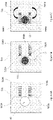
- Figures 3A to 3C illustrate a top view of an aerosol-generating device 20.
- the aerosol-generating device 20 of Figures 3A to 3C is not according to the present invention because it does not comprise an iris arrangement as required in appended claim 1.
- the device 20 does not comprise at least one holding member comprises a plurality of blades in an iris arrangement, each of said blades being configured to move from a first position, in which the aerosol-generating article can be inserted into the chamber via the opening; and a second position, in which each blade has reduced the size of the opening relative to the size of the opening when the blades are in the first position.
- FIGS. 3A to 3C are each taken along the longitudinal axis 52 of the chamber 50.
- a holding member 360 is disposed on the top wall 331 of the housing, adjacent to the opening 40.
- the holding member is shown in the first position in Figure 3A .
- the opening 40 is defined solely by the perimeter 332 of a substantially circular hole formed in the top wall 331 of the housing 30.
- the perimeter 332 solely defines the cross sectional area of the opening 40 as viewed from the top view of Figure 3A .
- Figure 3B illustrates the top view of the device 20, when an aerosol-generating article 10 has been inserted into the chamber of the device 20.
- the mouth end of the article extends out of the opening 40.
- the outer diameter of the article 10 is smaller than the diameter of the chamber 50.
- the cross-sectional area of the opening 40 as viewed from the top view of Figure 3B is greater than the transverse cross-sectional area of the aerosol-generating article 10.
- the aerosol-generating article 10 is therefore free to move within the chamber 50 of the device.
- the holding member 360 is movable from the first position of Figure 3B to the second position of Figure 3C .
- Movement can be achieved by sliding the holding member 360 along a guide track 365 in the top wall 31 of the housing 30.
- the holding member may comprise a main body which sits above the outer surface of the top wall 31 and a protruding portion (not shown), which extends into the underlying guide track 365 formed in said wall of the housing 30.
- the guide track 365 can define the extent of movement that the holding member 360 can have, relative to the housing 30.
- the size of the opening 40 has been reduced relative to the size of the opening 40 when the member is in the first position of Figure 3A .
- a portion of the holding member now overlies the hole in the top wall 31 of the housing, and thus reduces the cross-sectional area of the opening 40 as viewed from the top view of Figure 3C .
- the cross-sectional area of the opening 40 is now defined by both a portion of the perimeter 332 in the top wall 331 of the housing 30, and the external edge of an engaging portion 361 of the holding member 360.
- the holding member 360 when the holding member 360 is in the second position, a portion of the holding member 360 engages with the mouth end portion 11 of the article 10.
- the mouth end portion 11 of the article 10 is clamped between the engaging portion 361 of the holding member 360 and an engaging edge 334 of the opening 40 defined by the top wall 331 of the housing 30.
- the engaging portion 361 of the holding member 360 has a concave edge 364, which is shaped to complement the aerosol-generating article with which it engages.
- the holding member 360 may be coupled to a biasing member.
- the biasing member may be in the form of a helical spring.
- the biasing member may be configured to urge the holding member 360 to move towards the second position.
- a user will need to first overcome the biasing force of the spring to move the holding member 360 to the first position.
- the user can then insert an article 10 into the device 20 and release the holding member 360.
- the spring will then urge the holding member 360 back towards the second position, so that it engages with the mouth end portion 11 of the article 10 to hold the article in place by clamping the mouth end portion 11 of the article 10 between the concave edge 364 of the holding member 360 and the engaging edge 334 of the opening 340.
- the spring can therefore advantageously ensure that there is a sufficient clamping force on the article 10 to hold it in place.
- Figures 4A to 4C illustrate a top view of an aerosol-generating device.
- the aerosol-generating device 20 of Figures 4A to 4C is not according to the present invention because it does not comprise an iris arrangement as required in appended claim 1.
- the device 20 does not comprise at least one holding member comprises a plurality of blades in an iris arrangement, each of said blades being configured to move from a first position, in which the aerosol-generating article can be inserted into the chamber via the opening; and a second position, in which each blade has reduced the size of the opening relative to the size of the opening when the blades are in the first position.
- Figures 4A to 4C The arrangement of Figures 4A to 4C is similar to that of Figures 3A to 3C .
- the holding member 460 is now in the form of an arm, which is configured to move between the first and second positions, by way of rotation about a pivot point 462.
- the holding member 460 is in the first position; in Figure 4C , the holding member has pivoted about pivot point 462 to move into the second position. In the second position, the mouth end portion 11 of the article 10 is clamped between the holding member 460 and an engaging edge 434 of the opening 40 defined by the top wall 431 of the housing 30.
- the pivot movement is depicted by arrow 466.
- Figures 5A to 5C illustrate a top view of an aerosol-generating device 20.
- the aerosol-generating device 20 of Figures 5A to 5C is not according to the present invention because it does not comprise an iris arrangement as required in appended claim 1.
- the device 20 does not comprise at least one holding member comprises a plurality of blades in an iris arrangement, each of said blades being configured to move from a first position, in which the aerosol-generating article can be inserted into the chamber via the opening; and a second position, in which each blade has reduced the size of the opening relative to the size of the opening when the blades are in the first position.
- the holding mechanism comprises two holding members; namely a first holding member 560A, and a second holding member 560B.
- Each holding member 560A, 560B is in the form of an arm, which is configured to move between the first and second positions, by way of rotation about a respective pivot point 562A, 562B.
- each holding member 560A, 560B are in respective first positions; in Figure 5C , each holding member has pivoted about respective pivot point 562A, 562B to move into respective second position.
- the pivot movements are depicted by respective arrows 566A, 566B.
- the arms 560A, 560B and pivot points 562A, 562B are spaced to opposite sides of the chamber 50, by equal distances.
- both holding members 560A, 560B are in respective second positions, the article 10 is held in place within the device 20, but is not in contact with the perimeter 532 of the substantially circular hole formed in the top wall 531 of the housing 30. Instead, the mouth end portion 11 of the article 10 is now clamped between respective engaging portions of the two holding members 560A, 560B.
- the arrangement of Figures 5A and 5B can advantageously mean that the article 10 is held centrally within the chamber 40, and evenly spaced from the walls of the chamber 40. This may improve the consistency of the aerosol that is produced by articles 10 that are inserted into the device 20.
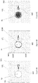
- Figures 6A to 6C illustrate a top view of an aerosol-generating device 20.
- the aerosol-generating device 20 of Figures 6A to 6C is not according to the present invention because it does not comprise an iris arrangement as required in appended claim 1.
- the device 20 does not comprise at least one holding member comprises a plurality of blades in an iris arrangement, each of said blades being configured to move from a first position, in which the aerosol-generating article can be inserted into the chamber via the opening; and a second position, in which each blade has reduced the size of the opening relative to the size of the opening when the blades are in the first position.
- the device 20 of Figures 6A to 6C is similar to the devices of Figures 3A-3C , 4A-4C and 5A-5C .
- the holding mechanism comprises first and second holding members 660A, 660B which are not disposed on the outer surface of the top wall 631 of the housing 30. Instead, the first and second holding members 660A, 660B underlie the inner surface of the top wall 631 of the housing 30.
- Figure 6A shows the first and second holding members when in the respective first positions. In this position, the opening 40 is defined solely by the perimeter 632 of a substantially circular hole formed in the top wall 631 of the housing 30. That is, the perimeter 632 solely defines the cross sectional area of the opening 40 as viewed from the top view of Figure 3A .
- the first and second holding members 660A, 660B entirely underlie the inner surface of the top wall 631 of the housing 30, and therefore are not visible or accessible to a user.
- the first and second holding members 660A, 660B are moved to the respective second positions, as shown in Figures 6B and 6C , at least a portion of the first and second holding members 660A, 660B move towards the opening 40 such that they no longer fully underlie the top wall 631 of the housing 30, but instead are exposed to the exterior of the device 20.
- the size of the opening 40 is reduced by the area of the first and second holding members 660A, 660B that is exposed. That is, the opening 40 is now defined solely by the engaging edges 664A, 664B of the first and second holding members 660A, 660B.
- Each engaging edge 664A, 664B is concave shaped.
- the holding mechanism of Figures 6A to 6C further comprises a control member 668 on the outer surface of the top wall 631 of the housing 30.
- the control member 668 is coupled to the first and second holding members 660A, 660B such that actuation of the control member 668 causes the first and second holding members 660A, 660B to move between the first and second positions.
- the control member 668 is an element that a user can slide to cause each of the first and second holding members 660A, 660B to move between their respective first and second positions.
- a user can slide the element 668 along a guide track 669 from the first position shown in Figure 6A to the second position shown in Figures 6B and 6C to move each of the first and second holding members 660A, 660B from their respective first positions to their respective second positions.
- the element 668 advantageously provides a user with a convenient means for moving the holding members 660A, 660B.
- a control member is advantageous in devices having one or more holding members substantially or entirely underlying the top wall of the housing in the first position, such that the holding member is substantially inaccessible to a user.
- the first and second holding members 660A, 660B of Figures 6A to 6C are substantially similar to the holding member 360shown in Figures 3A to 3C , having a similar shape and being arranged to slide between the first and second positions along tracks (not shown) in the housing 30.
- the first and second holding members 660A, 660B are configured to slide in opposite directions on movement of the control member 668 for clamping and releasing the aerosol-generating article 10 between them. It will be appreciated that the first and second holding members may be arranged to move between the first and second positions in other ways, such as by pivoting about a pivot point.
- Figures 7A to 7C illustrate a top view of an aerosol-generating device 20 according to an embodiment of the present invention.
- the embodiment of Figures 7A to 7C is similar to the device of Figures 5A to 5C .
- the holding mechanism comprises an iris at the opening 40 (see Figure 7B ).
- a plurality of holding members 760A, 760B are provided in the form of a plurality of blades in an iris arrangement.
- Each blade 760A, 760B is configured to move from a first position, in which the aerosol-generating article 10 can be inserted into the chamber via the opening 40; and a second position, in which the mouth end portion of the aerosol-generating article 10 can be held in place centrally in the opening 40, between the blades, each blade 760A, 760B having reduced the size of the opening 40 relative to the size of the opening 40 when the blades are in the first position.
- the holding member blades 760A, 760B are in the first position and completely underlie the inner surface of the top wall 731 of the housing 30. Therefore, in this configuration, the opening 40 is defined solely by the perimeter 732 of a substantially circular hole formed in the top wall 731 of the housing 30.
- the holding member blades 760A, 760B are moved to the second position, as shown in Figures 7B , the size of the opening 40 is reduced by the area of the blades that is exposed. Consequently, the opening 40 is now defined solely by the engaging edges the blades of the iris arrangement. Movement of the blades can be controlled by sliding control member 768 along guide track 769, in a similar manner to that described above with respect to Figures 6A to 6C .
Landscapes
- Containers And Packaging Bodies Having A Special Means To Remove Contents (AREA)
- Cameras Adapted For Combination With Other Photographic Or Optical Apparatuses (AREA)
Description
- The invention relates to an aerosol-generating device as defined in the
present claim 1, wherein such a device may be configured to heat articles containing a supply of aerosol-forming substrate. According to an embodiment, as defined inclaim 12, said aerosol-generating device may form part of an aerosol-generating system, such as a handheld electrically operated aerosol-generating system. - Articles in which an aerosol forming substrate, such as tobacco, is heated rather than combusted have been proposed in the art. Such articles are heated by an aerosol-generating device comprising a heater and a chamber, into which a portion of the article can be inserted. In particular, the aerosol-forming substrate portion of the article is inserted into the chamber, and heated to produce an aerosol. A mouth end portion of the article remains outside of the chamber, and a consumer can draw on this mouth end portion of the article to receive the aerosol. The chamber is typically an elongate cylinder, and substantially corresponds in size and shape to the size and shape of the aerosol-generating article with which the device is intended to be used. In order to appropriately locate the article in the chamber of the device, the device may comprise a heater in the form of a heater blade, which extends from the base of the chamber. When the article is inserted into the chamber the heater blade penetrates the article. In some devices, the heater blade may help to hold the article in place relative to the chamber. However, a heater blade may not always provide an appropriate means for holding the article in place, once it has been inserted into the chamber.
- It has also been proposed in the art to heat articles by other means, such as a heater assembly which extends around the outer surface of the chamber. Such a heater assembly may be chosen if the article to be heated is relatively slim, because a heater blade may risk damaging such an article when it is inserted into the chamber.
- In some devices, it may be desirable for the chamber of a device to have a width that is greater than the width of the articles to be heated in the chamber, in order to facilitate insertion of articles into the chamber and extraction of articles from the chamber. In particular, it may be necessary to facilitate extraction of an article from the chamber of devices comprising a heater assembly which extends around the outer surface of the chamber. This is because heating an article from the outer surface may weaken the structure of the article, particularly if the article has an outer wrapper formed from paper, which increases the risk of the article tearing as it is being removed from the chamber.
- It would therefore desirable to provide an improved arrangement for holding an aerosol-generating article once it has been inserted into an aerosol-generating device. It would also therefore be desirable to provide an improved arrangement for releasing an aerosol-generating article from an aerosol-generating device to facilitate extraction of the article from the device.
-
EP 3 228 199 A2 concerns an aerosol-generating device having a chamber for receiving an aerosol-generating article through an opening in the top wall of the device. The article is heated by heating elements which are disposed within the chamber and extend along a length of a side wall of the chamber. Heater element is movable from the position shown inFigure 1 ofEP 3 228 199 A2 , to the position shown inFigure 2 ofEP 3 228 199 A2 , in order to snugly engage an article when the article is in the chamber. Movement of the heater element is initiated by pressing a button on a side wall of the device. A double spring mechanism, is used to couple the button to the heating element, in a similar manner to a conventional pen lid and ink cartridge. -
GB 2 534 215 A Figure 2 ofGB 2 534 215 A Figure 1 ofGB 2 534 215 A GB 2 534 215 A - According to the invention, there is provided an aerosol-generating device for heating an aerosol-generating article, the device comprises: a housing having an opening; a chamber disposed within the housing, and configured to receive at least a portion of the aerosol-generating article through the opening in the housing; a heater assembly disposed within the housing, and comprising a heating element configured to heat at least a portion of the chamber; and a holding mechanism comprising at least one holding member disposed at or proximate to the opening of the housing, the at least one holding member comprising a plurality of blades in an iris arrangement, each of said blades being configured to move between: a first position, in which the aerosol-generating article can be inserted into the chamber through the opening; and a second position, in which each blade has reduced the size of the opening relative to the size of the opening when the blades are in the first position.
- By providing a device with a holding member that can be moved between such first and second positions, an article can be easily inserted into the chamber of the device (when the holding member is in the first position), and then securely held in place by the holding member after said insertion (when the holding member is in the second position).
- By providing the holding member at or about the opening in the housing, the holding member can engage with a portion of the article which is less likely to be subjected to high temperatures from the heating assembly, such as a mouth end portion of the article. This means that the holding member is less likely to affect the aerosol generating process, and therefore less likely to have an impact on the aerosol that is delivered to the consumer, than if the holding member was configured to engage with an aerosol-forming portion of the article. The mouth end portion may also be more resilient than the aerosol-forming portion of the article. This means that the mouth end portion of the article is less likely to be damaged by the holding member, than if the holding member were engaging with the aerosol-forming portion of the article.
- The arrangement of the present invention also enables the device to utilise heater arrangements other than heater blade arrangements, without substantial risk of the article moving within the chamber or falling out of the chamber, during use.
- In embodiments of the present invention, the holding mechanism is separate from or not the same component as the heater assembly. That is, the object or objects which form the holding mechanism are not the same as the object or objects which form the heater assembly. In this way, the function and performance of the heater assembly can remain unaffected by whether or not the at least one holding member is disposed in its first position or second position.
- Accordingly, the heater assembly and holding mechanism are arranged such that when an aerosol-generating article is received within the chamber, the heater assembly is configured to heat a first portion of the aerosol-generating article (such as an aerosol-forming portion) and the holding mechanism is configured to hold a second portion of the aerosol-generating article (such as a mouth end portion). For example, where the chamber has a longitudinal axis extending from the opening of the housing into the chamber, the heater assembly may be disposed within or around the chamber and longitudinally spaced from holding mechanism. More specifically, the holding mechanism may be disposed at or proximate the opening at a first longitudinal position, and the heater assembly may be disposed within or around the chamber at a second longitudinal position, the second longitudinal position being spaced further into the chamber than the first longitudinal position. Such an arrangement can reduce the likelihood of heating being affected by the holding mechanism. Such an arrangement can also mean that the holding mechanism is less likely to be subjected to high temperatures from the heater assembly.
- The holding mechanism may be configured such that, when an aerosol-generating article is received within the chamber, the at least one holding member can engage with and hold the aerosol-generating article in a position where the article is not in physical contact with the heater assembly or portion of the chamber heated by the heater assembly. This may help to ensure that no single portion of the aerosol-generating article is overheated. Put another way, this may help to ensure that the aerosol-generating article is more evenly heated.
- In some embodiments, the at least one holding member may be configured to substantially cover the portion of the opening between the outer surface of the article and the circumference of the opening defined by the housing when the at least one holding member is in the second position. For example, the holding mechanism may comprise a plurality of holding members arranged in an iris formation that substantially circumscribes an article received in the chamber when the holding members are in the second position. In these embodiments, the at least one holding member may substantially block or inhibit air from flowing out of the chamber between the external surface of the article and circumference of the opening defined by the housing when the at least one holding member is in the second position. As such, the at least one holding member may improve airflow through the article when the article is received in the device, as the holding member may reduce the proportion of air drawn through the device that does not pass through the article.
- The holding member is disposed at or proximate to the opening of the housing. The opening may be defined by a gap or hole in the housing, through which an aerosol-generating article can be inserted. In some embodiments, the holding member may be disposed on the outer surface of a wall of the housing. This allows a user to know the position of the holding member at all times. In some embodiments, the holding member may underlie the inner surface of a wall of the housing. For example, the entire holding member may underlie the inner surface of the wall of the housing when the holding member is in the first position. In this case, the holding member may not be visible to a user. However, when the holding member is moved to the second position, at least a portion of the holding member may move towards the opening such that it no longer underlies the wall of the housing, but is instead exposed to the exterior of the device. In this case, the size of the opening is reduced by the amount of the holding member that is exposed.
- As discussed in more detail below, the holding mechanism may comprise two or more opposing holding members at or proximate the opening, each holding member being movable relative to the chamber between the first and second positions. The opposing holding members may be arranged to provide opposing holding forces on an aerosol-generating article, when the article is received within the chamber and when the holding members are disposed in their second positions. This may help to ensure that the article can be held solely by the holding mechanism, rather than relying on a fixed portion of the housing or chamber wall to provide a requisite holding surface. This can therefore advantageously ensure that an aerosol-generating article may be placed into the device and held in a fixed position with respect to the device, without needing to come into direct physical contact with the heater assembly or a portion of the chamber which is heated by the heater assembly.
- In some embodiments, the holding member may be configured to slide between the first and second positions. In some embodiments, the holding member may be configured to rotate between the first and second positions.
- Preferably, the housing comprises a guide track along which the holding member can slide as the holding member moves between the first position and the second position. For example, the holding member may comprise a main body which sits above the outer surface of a wall of the housing and a protruding portion, which extends into an underlying guide track formed in said wall of the housing. The guide track can define the extent of movement that the holding member can have, relative to the housing.
- The holding mechanism comprises an iris at the opening. The iris is configured to open and close such that an aerosol-generating article can be inserted into the chamber through the opening when the iris is open, and then held in a fixed positioned relative to the chamber, by at least partially closing the iris around the mouth end portion of the aerosol-generating article. That is, the at least one holding member comprises a plurality of blades in an iris arrangement, each of said blades being configured to move from a first position, in which the aerosol-generating article can be inserted into the chamber via the opening; and a second position, in which each blade has reduced the size of the opening relative to the size of the opening when the blades are in the first position. The blades of the iris may be disposed on the under-side of a wall of the housing. Preferably, the blades of the iris completely underlie the wall of the housing when they are in their first position. Put another way, preferably the blades of the iris are not exposed to the exterior of the housing when they are in their first position.
- The at least one holding member may comprise a curved edge arranged to provide a holding surface when the holding member is in the second position. Preferably, the curved edge is a concave edge. By providing the holding member with such a curved or concave edge, the holding member can have a shape that complements the aerosol-generating article with which it engages. That is, aerosol-generating articles are commonly substantially cylindrical, and therefore the edge of the holding member can be shaped to complement the curved surface of the substantially cylindrical article which is inserted into the chamber. This can help to improve the engagement between the holding member and the aerosol-generating article. This can also help to better distribute any holding force that the holding member imposes on the aerosol-generating article, when the holding member is in the second position. This may advantageously minimise any potential damage that the holding member could cause to the aerosol generating article, when it is in the device.
- The device may be provided with a closure lid or cap for closing the opening. This may be advantageous for protecting the chamber from ingress of contaminants or other debris, when the device is not in use.
- In some embodiments, the at least one holding member is configured to move to a third position, in which the holding member completely closes the opening in the housing. This advantageously means that the holding member can be used for both: holding an article in a fixed position relative to the housing, when the article has been inserted into the device; and for protecting the chamber from ingress of contaminants or other debris, when the device is not in use.
- The holding mechanism may be configured to lock the holding member in one or more of the first second and third positions. In the case of the third position, this advantageously means that the chamber cannot become unintentionally exposed.
- Aerosol-generating articles are typically elongate cylinders. Preferably, the chamber is elongated and has a longitudinal axis extending from a base of the chamber to the opening.
- The holding mechanism may be configured such that the movement of the at least one holding member between the first position and the second position is substantially perpendicular or transverse to the longitudinal axis of the chamber. In other words, where the holding mechanism comprises a guide track along which the holding member can slide, the guide track may extend substantially perpendicular to the longitudinal axis of the chamber. In other words, where the holding mechanism comprises a pivot point, the pivot point may extend substantially parallel to the longitudinal axis of the chamber.
- The base of the chamber may be defined by a bottom wall. The base of the chamber may comprise one or more openings. Preferably, the chamber is cylindrical. The walls of the chamber may be formed of a thermally conductive material, such as metal.
- The heating assembly may comprise any suitable number of heating elements. The heating assembly may comprise a single heating element. The heating assembly may comprise at least one heating element. The heating assembly may comprise two heating elements. The heating assembly may comprise a plurality of heating elements. Where the heating assembly comprises a plurality of heating elements, the heating elements may be arranged at different locations at or around the chamber for heating different portions of the chamber. Where the chamber comprises a longitudinal axis, the heating elements may be spaced along the longitudinal axis. Where the heating assembly comprises a plurality of heating elements, the device may be configured to activate or heat each heating element at different times. The device may be configured to heat each heating element sequentially in a predetermined sequence.
- At least one wall of the chamber may be thermally coupled to the heater element. The heater assembly may comprise a heater element disposed around the outer surface of the at least one wall of the chamber.
- The heating element may be any suitable type of heating element. The heating element may be an electric heating element. The electric heating element may be a resistive heating element. The electric heating element may be an inductive heating element. The heating element may be in the form of a pin or a blade. The heater element may be one or more electrically conductive tracks on an electrically insulating substrate. The electrically conductive tracks may be electrically connected to a power supply. The electrically insulating substrate may be formed from polyimide. The electrically insulating substrate may extend around the outer surface of the at least one wall of the chamber. The electrically insulating substrate may be rolled into a tube. Where the heater assembly comprises more than one heater element, each heating element may be the same type of heating element or the heater assembly may comprise different types of heating element.
- The heater assembly may comprise a thermally insulating member disposed around the heater element. The thermally insulating member may be a dual walled tube that is disposed around the heater element. The dual walled tube may contain a vacuum between its two walls. Where the heater assembly comprises more than one heating element, the thermally insulating member may be disposed around more than one of the heating elements.
- The holding mechanism may comprise a biasing member configured to urge the holding member to move towards a set position. The biasing member may comprise a spring, such as a helical spring. Preferably, the set position is the second position. In this case, when the device is not in use the biasing member may urge the holding member into the second position. When a consumer wishes to use the device, they can push the holding member towards the first position, overcoming the biasing force. For example, they may slide or rotate the holding member from the second position to the first position. This will act to increase the size of the opening through which an article can be inserted. The consumer can then insert the article through the opening, so that a portion of the article resides in the chamber. The consumer can then release the holding member from the first position. The biasing force of the basing member then causes the holding member to revert towards the second position, whereby it engages with the aerosol-generating article, to help to hold the article in place relative to the housing.
- In some embodiments, the holding mechanism may comprise a locking mechanism for releasably locking the holding member in the second position. In these embodiments, the holding mechanism may comprise a biasing member configured to urge the holding member to move towards the first position, such that when the holding member is locked in the second position and the locking mechanism is released, the holding member is returned to the first position by the biasing member.
- In some embodiments, the holding mechanism may comprise a locking mechanism for releasably locking the holding member in the first position.
- A consumer may be able to directly move the at least one holding member between the first and second positions. For example, where the holding member comprises a main body which sits above the outer surface of a wall of the housing and a protruding portion and which extends into an underlying guide track formed in said wall of the housing, the consumer can move the holding member between the first and second positions with their fingers.
- The holding mechanism may further comprise a control member on the outer surface of the housing. The control member may be coupled to the holding member such that actuation of the control member causes the holding member to move between the first and second positions. In some embodiments, the control member may be a button, which a user can press to cause the holding member to move from the first position to the second position, or from the second position to the first position, or both. In some embodiments, the control member may be an element that a user can slide to cause the holding member to move between the first and second positions. The control member may be advantageous when the holding member at least partially underlies a wall of the housing, since the control member can provide a convenient facility for the consumer to interact with in order to move the holding member.
- The holding mechanism may be configured to move the holding member from the first position to the second position in response to activation of the heating assembly. For example, the holding mechanism may comprise a switch, which is electrically coupled to a temperature sensor. In such a case, the switch may be configured to initiate movement of the holding member from the first position to the second position, in response to receiving a signal from the temperature sensor indicating that a threshold temperature value has been reached. The switch may be electrically connected to a power supply, which is electrically connected to the heater assembly. In such a case, the switch may be configured to initiate movement of the holding member from the first position to the second position, in response to receiving a signal indicating that power is being supplied to the heater. In some embodiments, the heating element may be used as a temperature sensor, wherein the electrical resistance of the heating element may be measured and used as an indication of the temperature of the heating element.
- The holding mechanism may be configured to detect when a portion of an aerosol-generating article is disposed at the base of the chamber. The holding mechanism may further be configured to move the holding member from the first position to the second position in response to detecting that a portion of an aerosol-generating article is disposed at the base of the chamber. For example, the holding mechanism may comprise a switch, which is electrically coupled to a laser sensor in the chamber. In such a case, the switch may be configured to initiate movement of the holding member from the first position to the second position, in response to receiving a signal from the laser sensor indicating that an object is present in the base of the chamber.
- In some embodiments, the holding mechanism may further comprise a distal holding member disposed at or proximate to a distal end of the chamber, opposite the opening. The distal holding member may be configured to move between: a first position, in which the aerosol-generating article can be inserted into the chamber to at or around the distal end; and a second position, in which the holding member has reduced the size of the distal end of the chamber relative to the size of the distal end of the chamber when the distal holding member is in the first position. The holding element at or proximate the opening may be coupled to the distal holding element such that when the holding element at or proximate the opening is moved between the first and second positions, the distal holding element is also moved between the first and second positions.
- In particular the holding mechanism may comprise a distal holding member where the holding mechanism comprises two or more opposing holding members at or proximate the opening. In some particular embodiments, the holding mechanism may comprise a plurality of holding elements arranged in an iris arrangement at or proximate to the opening and a plurality of distal holding elements arranged in an iris arrangement at or proximate the distal end of the chamber.
- Advantageously, providing a holding mechanism with at least one distal holding element may further enable the holding mechanism to hold the article in place in the chamber when the holding elements are in the second position. Advantageously, providing a holding mechanism with at least one distal holding element may facilitate locating the article in the chamber, away from the chamber walls.
- As used herein, "electrically conductive" means formed from a material having a resistivity of 1×10⁻⁴ Ohm meter, or less. As used herein, "electrically insulating" means formed from a material having a resistivity of 1×10⁴ Ohm meter or more.
- Preferably, the aerosol-generating device comprises a power supply configured to supply power to the heating element. The power supply preferably comprises a power source. Preferably, the power source is a battery, such as a lithium ion battery. As an alternative, the power source may be another form of charge storage device such as a capacitor. The power source may require recharging. For example, the power source may have sufficient capacity to allow for the continuous generation of aerosol for a period of around six minutes or for a period that is a multiple of six minutes. In another example, the power source may have sufficient capacity to allow for a predetermined number of puffs or discrete activations of the heater assembly.
- The power supply may comprise control electronics. The control electronics may comprise a microcontroller. The microcontroller is preferably a programmable microcontroller. The electric circuitry may comprise further electronic components. The electric circuitry may be configured to regulate a supply of power to the heater assembly. Power may be supplied to the heater assembly continuously following activation of the system or may be supplied intermittently, such as on a puff-by-puff basis. The power may be supplied to the heater assembly in the form of pulses of electrical current.
- Preferably, the aerosol-generating system is a handheld system. Preferably, the aerosol-generating system is portable.
- It will be appreciated that preferred features described above in relation to one embodiment of the invention may also be applicable to other embodiments of the invention.
- Embodiments of the invention will now be described, by way of example only, with reference to the accompanying drawings, in which:
-
Figures 1A-1B show a perspective view of an aerosol-generating system comprising an aerosol-generating article and an aerosol-generating device not according to the present invention; -
Figure 2 shows a perspective view of the inside of the aerosol-generating device ofFigure 1 ; -
Figures 3A-3C show a top view of an aerosol-generating device not according to the present invention; -
Figures 4A-4C show a top view of an aerosol-generating device not according to the present invention; -
Figures 5A-5C show a top view of an aerosol-generating device not according to the present invention; -
Figures 6A-6C show a top view of an aerosol-generating device not according to the present invention; and -
Figures 7A-7C show a top view of an aerosol-generating device according to an embodiment of the present invention. -
Figures 1A-1B show a perspective view of an aerosol-generatingsystem 1 comprising an aerosol-generatingarticle 10 and an aerosol-generatingdevice 20. The aerosol-generatingdevice 20 ofFigures 1A-1B is not according to the present invention because it does not comprise an iris arrangement as required in appendedclaim 1. In particular, thedevice 20 does not comprise at least one holding member comprises a plurality of blades in an iris arrangement, each of said blades being configured to move from a first position, in which the aerosol-generating article can be inserted into the chamber via the opening; and a second position, in which each blade has reduced the size of the opening relative to the size of the opening when the blades are in the first position. - The
article 10 comprises amouth end portion 11 in the form of a mouth piece. The mouth end portion may comprise one or more mouthpiece segments, such as a hollow tube or a filter plug. Themouth end portion 11 is secured to an aerosol-formingportion 12 comprising an aerosol-forming substrate. The aerosol-forming substrate may be in the form of a paper wrapper circumscribing a rod of tobacco containing material. - The aerosol-generating
article 10 is configured to be inserted into the aerosol-generatingdevice 20. In particular, thedevice 20 comprises ahousing 30 having anopening 40 through which the article can be inserted. As best seen fromFigure 2 , thedevice 20 contains acylindrical chamber 50 within thehousing 30. Thechamber 50 has alongitudinal axis 52 extending from abase 54 of thechamber 50 to theopening 40. - The
chamber 50 is configured to receive at least the aerosol-formingportion 12 of the aerosol-forming article. In particular, as shown inFigure 1B , the aerosol-formingarticle 10 can be inserted into thedevice 20 through theopening 40 in thehousing 30, such that the aerosol-forming portion of thearticle 12 resides in thechamber 50, and at least part of themouth end portion 11 of thearticle 10 extends outside of thedevice 20. - As best seen from
Figure 2 , thechamber 50 is thermally coupled to aheater assembly 70, which is disposed in thedevice 20. Theheater assembly 70 may comprise a heater element comprising one or more electrically conductive tracks on an electrically insulating substrate. The electrically insulating substrate may circumscribe the cylindrical wall of thechamber 50. - The
heater assembly 70 is electrically connected to apower supply 80, which contains a power source in the form of a battery and control electronics for operating theheater assembly 70. Thepower supply 80 is also electrically connected to apower control button 85, which when actuated can control the supply of power to theheater assembly 70. - As shown in
Figures 1A-1B , thedevice 20 is provided with a holding mechanism comprising a holdingmember 60 disposed on the outer surface of thetop wall 31 of thehousing 30. The holdingmember 60 is disposed adjacent to theopening 40 and configured to move between: a first position, in which the aerosol-generatingarticle 10 can be inserted into thechamber 50 via theopening 40; and a second position, in which the holdingmember 70 has reduced the size of the opening relative to the size of the opening when the member is in the first position. This is best illustrated byFigures 3A to 7C , which are described in more detail below.Figures 3A to 7C are substantially similar toFigures 1A to 2 , and like reference numerals are used to refer to like features.Figures 3A to 7C differ fromFigures 1A to 2 by way of the holding mechanism at or proximate to the top wall of thedevice 20. -
Figures 3A to 3C illustrate a top view of an aerosol-generatingdevice 20. The aerosol-generatingdevice 20 ofFigures 3A to 3C is not according to the present invention because it does not comprise an iris arrangement as required in appendedclaim 1. In particular, thedevice 20 does not comprise at least one holding member comprises a plurality of blades in an iris arrangement, each of said blades being configured to move from a first position, in which the aerosol-generating article can be inserted into the chamber via the opening; and a second position, in which each blade has reduced the size of the opening relative to the size of the opening when the blades are in the first position. - The views shown in
Figures 3A to 3C are each taken along thelongitudinal axis 52 of thechamber 50. As shown inFigure 3A , a holdingmember 360 is disposed on thetop wall 331 of the housing, adjacent to theopening 40. The holding member is shown in the first position inFigure 3A . In this position, theopening 40 is defined solely by theperimeter 332 of a substantially circular hole formed in thetop wall 331 of thehousing 30. In this configuration, theperimeter 332 solely defines the cross sectional area of theopening 40 as viewed from the top view ofFigure 3A . -
Figure 3B illustrates the top view of thedevice 20, when an aerosol-generatingarticle 10 has been inserted into the chamber of thedevice 20. The mouth end of the article extends out of theopening 40. As can be seen fromFigure 3B , the outer diameter of thearticle 10 is smaller than the diameter of thechamber 50. As such, the cross-sectional area of theopening 40 as viewed from the top view ofFigure 3B is greater than the transverse cross-sectional area of the aerosol-generatingarticle 10. The aerosol-generatingarticle 10 is therefore free to move within thechamber 50 of the device. In order to more securely hold thearticle 10 in place within thedevice 20, the holdingmember 360 is movable from the first position ofFigure 3B to the second position ofFigure 3C . Movement can be achieved by sliding the holdingmember 360 along aguide track 365 in thetop wall 31 of thehousing 30. In particular, the holding member may comprise a main body which sits above the outer surface of thetop wall 31 and a protruding portion (not shown), which extends into theunderlying guide track 365 formed in said wall of thehousing 30. Theguide track 365 can define the extent of movement that the holdingmember 360 can have, relative to thehousing 30. With the device ofFigures 3A to 3C , a user may grasp the main body of the holding member with their hand and manually slide the holdingmember 360 along theguide track 365 between the first and second positions. - When the holding
member 360 is disposed in the second position shown inFigure 3C , the size of theopening 40 has been reduced relative to the size of theopening 40 when the member is in the first position ofFigure 3A . This is because a portion of the holding member now overlies the hole in thetop wall 31 of the housing, and thus reduces the cross-sectional area of theopening 40 as viewed from the top view ofFigure 3C . In particular, the cross-sectional area of theopening 40 is now defined by both a portion of theperimeter 332 in thetop wall 331 of thehousing 30, and the external edge of an engagingportion 361 of the holdingmember 360. - Therefore, when the holding
member 360 is in the second position, a portion of the holdingmember 360 engages with themouth end portion 11 of thearticle 10. In particular, when the holdingmember 360 is in the second position, themouth end portion 11 of thearticle 10 is clamped between the engagingportion 361 of the holdingmember 360 and anengaging edge 334 of theopening 40 defined by thetop wall 331 of thehousing 30. These edges together act to hold thearticle 10 in place with respect to thedevice 20. The engagingportion 361 of the holdingmember 360 has aconcave edge 364, which is shaped to complement the aerosol-generating article with which it engages. - Although not shown in
Figures 3A to 3C , the holdingmember 360 may be coupled to a biasing member. The biasing member may be in the form of a helical spring. The biasing member may be configured to urge the holdingmember 360 to move towards the second position. In such a scenario, a user will need to first overcome the biasing force of the spring to move the holdingmember 360 to the first position. The user can then insert anarticle 10 into thedevice 20 and release the holdingmember 360. The spring will then urge the holdingmember 360 back towards the second position, so that it engages with themouth end portion 11 of thearticle 10 to hold the article in place by clamping themouth end portion 11 of thearticle 10 between theconcave edge 364 of the holdingmember 360 and theengaging edge 334 of the opening 340. The spring can therefore advantageously ensure that there is a sufficient clamping force on thearticle 10 to hold it in place. -
Figures 4A to 4C illustrate a top view of an aerosol-generating device. The aerosol-generatingdevice 20 ofFigures 4A to 4C is not according to the present invention because it does not comprise an iris arrangement as required in appendedclaim 1. In particular, thedevice 20 does not comprise at least one holding member comprises a plurality of blades in an iris arrangement, each of said blades being configured to move from a first position, in which the aerosol-generating article can be inserted into the chamber via the opening; and a second position, in which each blade has reduced the size of the opening relative to the size of the opening when the blades are in the first position. - The arrangement of
Figures 4A to 4C is similar to that ofFigures 3A to 3C . However, inFigures 4A to 4C , the holdingmember 460 is now in the form of an arm, which is configured to move between the first and second positions, by way of rotation about apivot point 462. - In
Figures 4A and 4B , the holdingmember 460 is in the first position; inFigure 4C , the holding member has pivoted aboutpivot point 462 to move into the second position. In the second position, themouth end portion 11 of thearticle 10 is clamped between the holdingmember 460 and anengaging edge 434 of theopening 40 defined by thetop wall 431 of thehousing 30. The pivot movement is depicted byarrow 466. -
Figures 5A to 5C illustrate a top view of an aerosol-generatingdevice 20. The aerosol-generatingdevice 20 ofFigures 5A to 5C is not according to the present invention because it does not comprise an iris arrangement as required in appendedclaim 1. In particular, thedevice 20 does not comprise at least one holding member comprises a plurality of blades in an iris arrangement, each of said blades being configured to move from a first position, in which the aerosol-generating article can be inserted into the chamber via the opening; and a second position, in which each blade has reduced the size of the opening relative to the size of the opening when the blades are in the first position. - The arrangement of
Figures 5A to 5C is similar to that ofFigures 4A to 4C . However, inFigures 5A to 5C , the holding mechanism comprises two holding members; namely a first holdingmember 560A, and asecond holding member 560B. Each holdingmember respective pivot point - In
Figures 5A and 5B , the holdingmembers Figure 5C , each holding member has pivoted aboutrespective pivot point respective arrows arms pivot points chamber 50, by equal distances. - In this arrangement, when both holding
members article 10 is held in place within thedevice 20, but is not in contact with theperimeter 532 of the substantially circular hole formed in thetop wall 531 of thehousing 30. Instead, themouth end portion 11 of thearticle 10 is now clamped between respective engaging portions of the two holdingmembers Figures 5A and 5B can advantageously mean that thearticle 10 is held centrally within thechamber 40, and evenly spaced from the walls of thechamber 40. This may improve the consistency of the aerosol that is produced byarticles 10 that are inserted into thedevice 20. -
Figures 6A to 6C illustrate a top view of an aerosol-generatingdevice 20. The aerosol-generatingdevice 20 ofFigures 6A to 6C is not according to the present invention because it does not comprise an iris arrangement as required in appendedclaim 1. In particular, thedevice 20 does not comprise at least one holding member comprises a plurality of blades in an iris arrangement, each of said blades being configured to move from a first position, in which the aerosol-generating article can be inserted into the chamber via the opening; and a second position, in which each blade has reduced the size of the opening relative to the size of the opening when the blades are in the first position. - The
device 20 ofFigures 6A to 6C is similar to the devices ofFigures 3A-3C ,4A-4C and5A-5C . However, inFigures 6A to 6C the holding mechanism comprises first andsecond holding members top wall 631 of thehousing 30. Instead, the first andsecond holding members top wall 631 of thehousing 30.Figure 6A shows the first and second holding members when in the respective first positions. In this position, theopening 40 is defined solely by theperimeter 632 of a substantially circular hole formed in thetop wall 631 of thehousing 30. That is, theperimeter 632 solely defines the cross sectional area of theopening 40 as viewed from the top view ofFigure 3A . - In
Figure 6A , the first andsecond holding members top wall 631 of thehousing 30, and therefore are not visible or accessible to a user. However, when the first andsecond holding members Figures 6B and 6C , at least a portion of the first andsecond holding members top wall 631 of thehousing 30, but instead are exposed to the exterior of thedevice 20. In this configuration, the size of theopening 40 is reduced by the area of the first andsecond holding members opening 40 is now defined solely by the engagingedges second holding members edge - The holding mechanism of
Figures 6A to 6C further comprises acontrol member 668 on the outer surface of thetop wall 631 of thehousing 30. Thecontrol member 668 is coupled to the first andsecond holding members control member 668 causes the first andsecond holding members Figures 6A to 6C thecontrol member 668 is an element that a user can slide to cause each of the first andsecond holding members element 668 along aguide track 669 from the first position shown inFigure 6A to the second position shown inFigures 6B and 6C to move each of the first andsecond holding members element 668 advantageously provides a user with a convenient means for moving the holdingmembers - The first and
second holding members Figures 6A to 6C are substantially similar to the holding member 360shown inFigures 3A to 3C , having a similar shape and being arranged to slide between the first and second positions along tracks (not shown) in thehousing 30. The first andsecond holding members control member 668 for clamping and releasing the aerosol-generatingarticle 10 between them. It will be appreciated that the first and second holding members may be arranged to move between the first and second positions in other ways, such as by pivoting about a pivot point. -
Figures 7A to 7C illustrate a top view of an aerosol-generatingdevice 20 according to an embodiment of the present invention. The embodiment ofFigures 7A to 7C is similar to the device ofFigures 5A to 5C . However, in the embodiment ofFigures 7A to 7C the holding mechanism comprises an iris at the opening 40 (seeFigure 7B ). In particular, a plurality of holdingmembers blade article 10 can be inserted into the chamber via theopening 40; and a second position, in which the mouth end portion of the aerosol-generatingarticle 10 can be held in place centrally in theopening 40, between the blades, eachblade opening 40 relative to the size of theopening 40 when the blades are in the first position. This can be best appreciated fromFigures 7A and 7B . - In
Figure 7A , the holdingmember blades top wall 731 of thehousing 30. Therefore, in this configuration, theopening 40 is defined solely by theperimeter 732 of a substantially circular hole formed in thetop wall 731 of thehousing 30. However, when the holdingmember blades Figures 7B , the size of theopening 40 is reduced by the area of the blades that is exposed. Consequently, theopening 40 is now defined solely by the engaging edges the blades of the iris arrangement. Movement of the blades can be controlled by slidingcontrol member 768 alongguide track 769, in a similar manner to that described above with respect toFigures 6A to 6C .
Claims (12)
- An aerosol-generating device (20) for heating an aerosol-generating article (10), the device comprising:a housing (30) having an opening (40);a chamber (50) disposed within the housing (30), and configured to receive at least a portion of the aerosol-generating article through the opening in the housing (30);a heater assembly (70) disposed within the housing (30), and comprising a heating element configured to heat at least a portion of the chamber (50); anda holding mechanism comprising at least one holding member disposed at or proximate to the opening of the housing, the at least one holding member comprising a plurality of blades (760A, 760B) in an iris arrangement, each of said blades (760A, 760B) being configured to move between:a first position, in which the aerosol-generating article (10) can be inserted into the chamber (50) via the opening (40); anda second position, in which each blade (760A, 760B) has reduced the size of the opening (40) relative to the size of the opening (40) when the blades (760A, 760B) are in the first position.
- An aerosol-generating device (20) according to claim 1, wherein the holding member is disposed on the outer surface of a wall of the housing (30), or wherein the holding member underlies the inner surface of a wall of the housing (30).
- An aerosol-generating device (20) according to any one of claim 1 or 2, wherein the at least one holding member comprises a concave edge arranged to provide a holding surface when the holding member is in the second position.
- An aerosol-generating device (20) according to any one of the preceding claims, wherein the at least one holding member is configured to move to a third position, in which the holding member completely closes the opening in the housing (30).
- An aerosol-generating device (20) according to any one of the preceding claims, wherein the chamber (50) is elongated and has a longitudinal axis extending from a base (54) of the chamber (50) to the opening (40).
- An aerosol-generating device (20) according to any one of the preceding claims, wherein at least one wall of the chamber (50) is thermally coupled to the heater element.
- An aerosol-generating device (20) according to claim 6, wherein the heater assembly (70) comprises a heater element disposed around the outer surface of the at least one wall of the chamber (50).
- An aerosol-generating device (20) according to any one of the preceding claims, wherein the holding mechanism comprises a control member (768) on the outer surface of the housing (30), the control member (768) being coupled to the holding member such that actuation of the control member (768) causes the holding member to move between the first and second positions.
- An aerosol-generating device (20) according to claim 8, wherein the holding mechanism comprises a biasing member configured to urge the holding member to move towards a set position.
- An aerosol-generating device (20) according to any one of the preceding claims, wherein the holding mechanism is coupled to the heating assembly, and configured to move the holding member from the first position to the second position in response to activation of the heating assembly.
- An aerosol-generating device (20) according to any one of the preceding claims, wherein the holding mechanism is configured to detect when a portion of an aerosol-generating article is disposed at the base of the chamber, and configured to move the holding member from the first position to the second position in response to detecting that a portion of an aerosol-generating article is disposed at the base of the chamber.
- An aerosol-generating system comprising an aerosol-generating device (20) according to any one of claims 1 to 11, and an aerosol-generating article (10) configured to be inserted into the chamber (50) of the aerosol-generating device (20).
Applications Claiming Priority (2)
| Application Number | Priority Date | Filing Date | Title |
|---|---|---|---|
| EP17198144 | 2017-10-24 | ||
| PCT/EP2018/079206 WO2019081602A1 (en) | 2017-10-24 | 2018-10-24 | Aerosol-generating device having holding mechanism |
Publications (2)
| Publication Number | Publication Date |
|---|---|
| EP3700369A1 EP3700369A1 (en) | 2020-09-02 |
| EP3700369B1 true EP3700369B1 (en) | 2022-08-03 |
Family
ID=60182422
Family Applications (1)
| Application Number | Title | Priority Date | Filing Date |
|---|---|---|---|
| EP18789674.1A Active EP3700369B1 (en) | 2017-10-24 | 2018-10-24 | Aerosol-generating device having holding mechanism |
Country Status (8)
| Country | Link |
|---|---|
| US (2) | US11819057B2 (en) |
| EP (1) | EP3700369B1 (en) |
| JP (2) | JP7432504B2 (en) |
| KR (2) | KR20240096652A (en) |
| CN (1) | CN111148443A (en) |
| BR (1) | BR112020007018A2 (en) |
| RU (1) | RU2771102C2 (en) |
| WO (1) | WO2019081602A1 (en) |
Families Citing this family (12)
| Publication number | Priority date | Publication date | Assignee | Title |
|---|---|---|---|---|
| KR20210050569A (en) * | 2018-12-06 | 2021-05-07 | 필립모리스 프로덕츠 에스.에이. | Aerosol-generating article with narrow hollow tubular filter |
| US12059033B2 (en) * | 2019-01-15 | 2024-08-13 | Philip Morris Products S.A. | Aerosol-generating device with closable cavity |
| CN112535320A (en) * | 2019-09-05 | 2021-03-23 | 深圳市合元科技有限公司 | Aerosol generator |
| CN114599244A (en) * | 2019-10-17 | 2022-06-07 | 菲利普莫里斯生产公司 | Charger with rotatable lid and aerosol generating system |
| US20230111319A1 (en) * | 2019-10-17 | 2023-04-13 | Philip Morris Products S.A. | Charger and aerosol-generating system with a multi-component cover |
| JP2022552966A (en) * | 2019-10-17 | 2022-12-21 | フィリップ・モーリス・プロダクツ・ソシエテ・アノニム | Charger and aerosol generating system with improved closure means |
| CN114745982A (en) * | 2019-12-03 | 2022-07-12 | 日本烟草国际股份有限公司 | Aerosol generating device with baffle |
| WO2021152035A1 (en) * | 2020-01-29 | 2021-08-05 | Philip Morris Products S.A. | An adjustable retaining member for an aerosol-generating device |
| WO2021186880A1 (en) | 2020-03-18 | 2021-09-23 | 日本たばこ産業株式会社 | Aspiration device, information processing method and program |
| CN112369689A (en) * | 2020-11-27 | 2021-02-19 | 云南中烟工业有限责任公司 | Aerosol generating device capable of realizing bidirectional suction |
| GB202101465D0 (en) * | 2021-02-03 | 2021-03-17 | Nicoventures Trading Ltd | Non-combustible aerosol provision device |
| WO2022215256A1 (en) * | 2021-04-09 | 2022-10-13 | 日本たばこ産業株式会社 | Flavor inhaler and smoking system |
Family Cites Families (42)
| Publication number | Priority date | Publication date | Assignee | Title |
|---|---|---|---|---|
| US4466448A (en) | 1981-04-13 | 1984-08-21 | Aikman Leslie N | Tobacco smoke filter |
| JP3325591B2 (en) | 1990-08-24 | 2002-09-17 | フィリップ・モーリス・プロダクツ・インコーポレイテッド | Smoking articles |
| US5730181A (en) * | 1994-07-15 | 1998-03-24 | Unit Instruments, Inc. | Mass flow controller with vertical purifier |
| JPH09289065A (en) * | 1996-04-25 | 1997-11-04 | Sony Corp | Card slot unit, manufacture thereof, and computer device |
| US5706832A (en) | 1996-11-13 | 1998-01-13 | Jupiter Products Co., Inc. | Cigar holder |
| WO2001070054A1 (en) | 2000-03-23 | 2001-09-27 | Philip Morris Products Inc. | Electrical smoking system and method |
| US6884120B1 (en) * | 2002-06-27 | 2005-04-26 | Siliconpipe, Inc. | Array connector with deflectable coupling structure for mating with other components |
| CN101685028B (en) * | 2002-09-20 | 2011-09-21 | 矢崎总业株式会社 | Connector assembly and meter employing the same |
| US20070235047A1 (en) | 2006-04-11 | 2007-10-11 | Dean Long | Grasping device for retaining an article |
| US9192195B2 (en) | 2009-09-22 | 2015-11-24 | Rocco Dolciato | Holder for smoking article |
| US9054440B2 (en) * | 2009-10-19 | 2015-06-09 | Adc Telecommunications, Inc. | Managed electrical connectivity systems |
| JP5604449B2 (en) * | 2009-12-14 | 2014-10-08 | パナソニック株式会社 | Car charger |
| CN201602128U (en) | 2009-12-22 | 2010-10-13 | 湖北中烟工业有限责任公司 | Multifunctional cigarette holding device |
| SG184636A1 (en) * | 2011-03-11 | 2012-10-30 | Keppel Offshore & Marine Technology Ct Pte Ltd | Offshore systems and methods for liquefied gas production, storage and offloading to reduce and prevent damage |
| ES2637322T3 (en) * | 2011-10-25 | 2017-10-11 | Philip Morris Products S.A. | Aerosol generating device with heating unit |
| BR122019024735B1 (en) | 2011-11-21 | 2022-03-29 | Philip Morris Products S.A. | Aerosol forming substrate extractor, aerosol generating device and extractor for an electrically heated smoke system |
| KR102068756B1 (en) | 2011-12-30 | 2020-01-22 | 필립모리스 프로덕츠 에스.에이. | Smoking article with front-plug and aerosol-forming substrate and method |
| MY168388A (en) * | 2012-01-03 | 2018-10-31 | Philip Morris Products Sa | Power supply system for portable aerosol-generating device |
| US8591265B2 (en) * | 2012-01-05 | 2013-11-26 | Cheng Uei Precision Industry Co., Ltd. | Receptacle connector |
| US8864520B2 (en) * | 2012-12-04 | 2014-10-21 | Cheng Uei Precision Industry Co., Ltd. | Electrical connector |
| US10193211B2 (en) * | 2014-08-10 | 2019-01-29 | Féinics Amatech Teoranta | Smartcards, RFID devices, wearables and methods |
| US10599972B2 (en) * | 2013-01-18 | 2020-03-24 | Féinics Amatech Teoranta | Smartcard constructions and methods |
| GB2511306A (en) | 2013-02-27 | 2014-09-03 | British American Tobacco Co | A smoking device |
| WO2014195687A1 (en) | 2013-06-04 | 2014-12-11 | Nicoventures Holdings Limited | Container |
| US10292424B2 (en) * | 2013-10-31 | 2019-05-21 | Rai Strategic Holdings, Inc. | Aerosol delivery device including a pressure-based aerosol delivery mechanism |
| CN204056645U (en) | 2014-08-27 | 2014-12-31 | 朱卫清 | The transmission device of gear blade cover of dust |
| CN107105767B (en) | 2014-11-14 | 2021-01-01 | Jt国际公司 | Container for an aerosol generating device |
| EP3232832A1 (en) | 2014-12-18 | 2017-10-25 | JT International SA | Container for an aerosol generating device |
| GB2534215B (en) | 2015-01-19 | 2017-08-09 | Ngip Res Ltd | Aerosol-generating device |
| KR102694916B1 (en) | 2015-02-06 | 2024-08-16 | 필립모리스 프로덕츠 에스.에이. | Improved extractor for an aerosol-generating device |
| CN104770878B (en) | 2015-03-23 | 2017-11-24 | 云南中烟工业有限责任公司 | A kind of electric heating type cigarette smoking device with electronic cigarette pumping function |
| KR102409852B1 (en) | 2015-06-26 | 2022-06-15 | 니코벤처스 트레이딩 리미티드 | Apparatus for heating smokable material |
| CN205005900U (en) | 2015-09-25 | 2016-02-03 | 余东 | Novel carbon separates for shredded tobacco for water pipes |
| US10058125B2 (en) * | 2015-10-13 | 2018-08-28 | Rai Strategic Holdings, Inc. | Method for assembling an aerosol delivery device |
| RU2714794C2 (en) | 2015-12-29 | 2020-02-19 | Филип Моррис Продактс С.А. | Holder for aerosol-generating article |
| CN207040892U (en) | 2016-07-23 | 2018-02-27 | 深圳市合元科技有限公司 | Baking formula smoking set |
| CN206213269U (en) | 2016-10-28 | 2017-06-06 | 红塔烟草(集团)有限责任公司 | A kind of cigarette filter of adjustable gas output |
| KR20170000467U (en) * | 2017-01-12 | 2017-02-02 | 주식회사 손엔 | Vaporizing apparatus having function of preventing leak |
| US10973008B2 (en) * | 2018-03-12 | 2021-04-06 | Apple Inc. | Wireless device preferred bandwidth part configuration and duty cycle indication |
| US10777877B2 (en) * | 2018-06-05 | 2020-09-15 | Plume Design, Inc. | Compact, direct plugged, and high-performance Wi-Fi access point |
| CN111416230A (en) * | 2020-01-21 | 2020-07-14 | 东莞立讯技术有限公司 | Fan connector |
| TWI710168B (en) * | 2020-01-21 | 2020-11-11 | 大陸商東莞立訊技術有限公司 | Connector |
-
2018
- 2018-10-24 JP JP2020520789A patent/JP7432504B2/en active Active
- 2018-10-24 WO PCT/EP2018/079206 patent/WO2019081602A1/en active Search and Examination
- 2018-10-24 EP EP18789674.1A patent/EP3700369B1/en active Active
- 2018-10-24 BR BR112020007018-1A patent/BR112020007018A2/en active Search and Examination
- 2018-10-24 KR KR1020247018427A patent/KR20240096652A/en unknown
- 2018-10-24 US US16/754,208 patent/US11819057B2/en active Active
- 2018-10-24 KR KR1020207010756A patent/KR102672786B1/en active IP Right Grant
- 2018-10-24 CN CN201880063873.3A patent/CN111148443A/en active Pending
- 2018-10-24 RU RU2020116768A patent/RU2771102C2/en active
-
2023
- 2023-08-24 US US18/455,404 patent/US20230397663A1/en active Pending
-
2024
- 2024-02-05 JP JP2024015780A patent/JP2024042082A/en active Pending
Also Published As
| Publication number | Publication date |
|---|---|
| RU2020116768A (en) | 2021-11-25 |
| RU2771102C2 (en) | 2022-04-26 |
| WO2019081602A1 (en) | 2019-05-02 |
| BR112020007018A2 (en) | 2020-10-06 |
| EP3700369A1 (en) | 2020-09-02 |
| JP2024042082A (en) | 2024-03-27 |
| RU2020116768A3 (en) | 2021-11-25 |
| KR102672786B1 (en) | 2024-06-07 |
| US20200268047A1 (en) | 2020-08-27 |
| US20230397663A1 (en) | 2023-12-14 |
| KR20240096652A (en) | 2024-06-26 |
| KR20200076679A (en) | 2020-06-29 |
| JP2021500018A (en) | 2021-01-07 |
| CN111148443A (en) | 2020-05-12 |
| JP7432504B2 (en) | 2024-02-16 |
| US11819057B2 (en) | 2023-11-21 |
Similar Documents
| Publication | Publication Date | Title |
|---|---|---|
| EP3700369B1 (en) | Aerosol-generating device having holding mechanism | |
| US11963553B2 (en) | Aerosol-generating device comprising a cover element sensor | |
| JP7356436B2 (en) | Aerosol generator with cover element | |
| US11998058B2 (en) | Aerosol-generating device comprising a cover element sensor | |
| US12089634B2 (en) | Aerosol-generating device comprising a cover element mechanism | |
| US11910839B2 (en) | Case for aerosol-generating device with detector | |
| WO2019170886A1 (en) | An aerosol-generating device comprising a sensor for a movable element | |
| RU2785694C2 (en) | Aerosol generating device containing mechanism of element in form of cover and aerosol generating system | |
| US20240315329A1 (en) | An aerosol-generating device comprising a cover element | |
| RU2778825C2 (en) | Aerosol generating device containing element sensor in form of lid | |
| KR102708939B1 (en) | Aerosol generating device comprising a cover element mechanism | |
| RU2786608C2 (en) | Aerosol generating device containing cover element and aerosol generating system | |
| JP2024525702A (en) | Aerosol generating device with a closing member |
Legal Events
| Date | Code | Title | Description |
|---|---|---|---|
| STAA | Information on the status of an ep patent application or granted ep patent |
Free format text: STATUS: UNKNOWN |
|
| STAA | Information on the status of an ep patent application or granted ep patent |
Free format text: STATUS: THE INTERNATIONAL PUBLICATION HAS BEEN MADE |
|
| PUAI | Public reference made under article 153(3) epc to a published international application that has entered the european phase |
Free format text: ORIGINAL CODE: 0009012 |
|
| STAA | Information on the status of an ep patent application or granted ep patent |
Free format text: STATUS: REQUEST FOR EXAMINATION WAS MADE |
|
| 17P | Request for examination filed |
Effective date: 20200318 |
|
| AK | Designated contracting states |
Kind code of ref document: A1 Designated state(s): AL AT BE BG CH CY CZ DE DK EE ES FI FR GB GR HR HU IE IS IT LI LT LU LV MC MK MT NL NO PL PT RO RS SE SI SK SM TR |
|
| AX | Request for extension of the european patent |
Extension state: BA ME |
|
| DAV | Request for validation of the european patent (deleted) | ||
| DAX | Request for extension of the european patent (deleted) | ||
| REG | Reference to a national code |
Ref country code: DE Ref legal event code: R079 Ref document number: 602018038835 Country of ref document: DE Free format text: PREVIOUS MAIN CLASS: A24F0047000000 Ipc: A24F0040200000 |
|
| GRAP | Despatch of communication of intention to grant a patent |
Free format text: ORIGINAL CODE: EPIDOSNIGR1 |
|
| STAA | Information on the status of an ep patent application or granted ep patent |
Free format text: STATUS: GRANT OF PATENT IS INTENDED |
|
| RIC1 | Information provided on ipc code assigned before grant |
Ipc: A24F 40/50 20200101ALI20220214BHEP Ipc: A24F 40/485 20200101ALI20220214BHEP Ipc: A24F 40/40 20200101ALI20220214BHEP Ipc: A24F 40/20 20200101AFI20220214BHEP |
|
| INTG | Intention to grant announced |
Effective date: 20220302 |
|
| GRAS | Grant fee paid |
Free format text: ORIGINAL CODE: EPIDOSNIGR3 |
|
| GRAA | (expected) grant |
Free format text: ORIGINAL CODE: 0009210 |
|
| STAA | Information on the status of an ep patent application or granted ep patent |
Free format text: STATUS: THE PATENT HAS BEEN GRANTED |
|
| AK | Designated contracting states |
Kind code of ref document: B1 Designated state(s): AL AT BE BG CH CY CZ DE DK EE ES FI FR GB GR HR HU IE IS IT LI LT LU LV MC MK MT NL NO PL PT RO RS SE SI SK SM TR |
|
| REG | Reference to a national code |
Ref country code: AT Ref legal event code: REF Ref document number: 1508033 Country of ref document: AT Kind code of ref document: T Effective date: 20220815 Ref country code: CH Ref legal event code: EP |
|
| REG | Reference to a national code |
Ref country code: DE Ref legal event code: R096 Ref document number: 602018038835 Country of ref document: DE |
|
| REG | Reference to a national code |
Ref country code: IE Ref legal event code: FG4D |
|
| REG | Reference to a national code |
Ref country code: NL Ref legal event code: FP |
|
| REG | Reference to a national code |
Ref country code: LT Ref legal event code: MG9D |
|
| PG25 | Lapsed in a contracting state [announced via postgrant information from national office to epo] |
Ref country code: SE Free format text: LAPSE BECAUSE OF FAILURE TO SUBMIT A TRANSLATION OF THE DESCRIPTION OR TO PAY THE FEE WITHIN THE PRESCRIBED TIME-LIMIT Effective date: 20220803 Ref country code: RS Free format text: LAPSE BECAUSE OF FAILURE TO SUBMIT A TRANSLATION OF THE DESCRIPTION OR TO PAY THE FEE WITHIN THE PRESCRIBED TIME-LIMIT Effective date: 20220803 Ref country code: PT Free format text: LAPSE BECAUSE OF FAILURE TO SUBMIT A TRANSLATION OF THE DESCRIPTION OR TO PAY THE FEE WITHIN THE PRESCRIBED TIME-LIMIT Effective date: 20221205 Ref country code: NO Free format text: LAPSE BECAUSE OF FAILURE TO SUBMIT A TRANSLATION OF THE DESCRIPTION OR TO PAY THE FEE WITHIN THE PRESCRIBED TIME-LIMIT Effective date: 20221103 Ref country code: LV Free format text: LAPSE BECAUSE OF FAILURE TO SUBMIT A TRANSLATION OF THE DESCRIPTION OR TO PAY THE FEE WITHIN THE PRESCRIBED TIME-LIMIT Effective date: 20220803 Ref country code: LT Free format text: LAPSE BECAUSE OF FAILURE TO SUBMIT A TRANSLATION OF THE DESCRIPTION OR TO PAY THE FEE WITHIN THE PRESCRIBED TIME-LIMIT Effective date: 20220803 Ref country code: FI Free format text: LAPSE BECAUSE OF FAILURE TO SUBMIT A TRANSLATION OF THE DESCRIPTION OR TO PAY THE FEE WITHIN THE PRESCRIBED TIME-LIMIT Effective date: 20220803 Ref country code: ES Free format text: LAPSE BECAUSE OF FAILURE TO SUBMIT A TRANSLATION OF THE DESCRIPTION OR TO PAY THE FEE WITHIN THE PRESCRIBED TIME-LIMIT Effective date: 20220803 |
|
| REG | Reference to a national code |
Ref country code: AT Ref legal event code: MK05 Ref document number: 1508033 Country of ref document: AT Kind code of ref document: T Effective date: 20220803 |
|
| PG25 | Lapsed in a contracting state [announced via postgrant information from national office to epo] |
Ref country code: PL Free format text: LAPSE BECAUSE OF FAILURE TO SUBMIT A TRANSLATION OF THE DESCRIPTION OR TO PAY THE FEE WITHIN THE PRESCRIBED TIME-LIMIT Effective date: 20220803 Ref country code: IS Free format text: LAPSE BECAUSE OF FAILURE TO SUBMIT A TRANSLATION OF THE DESCRIPTION OR TO PAY THE FEE WITHIN THE PRESCRIBED TIME-LIMIT Effective date: 20221203 Ref country code: HR Free format text: LAPSE BECAUSE OF FAILURE TO SUBMIT A TRANSLATION OF THE DESCRIPTION OR TO PAY THE FEE WITHIN THE PRESCRIBED TIME-LIMIT Effective date: 20220803 Ref country code: GR Free format text: LAPSE BECAUSE OF FAILURE TO SUBMIT A TRANSLATION OF THE DESCRIPTION OR TO PAY THE FEE WITHIN THE PRESCRIBED TIME-LIMIT Effective date: 20221104 |
|
| PG25 | Lapsed in a contracting state [announced via postgrant information from national office to epo] |
Ref country code: SM Free format text: LAPSE BECAUSE OF FAILURE TO SUBMIT A TRANSLATION OF THE DESCRIPTION OR TO PAY THE FEE WITHIN THE PRESCRIBED TIME-LIMIT Effective date: 20220803 Ref country code: RO Free format text: LAPSE BECAUSE OF FAILURE TO SUBMIT A TRANSLATION OF THE DESCRIPTION OR TO PAY THE FEE WITHIN THE PRESCRIBED TIME-LIMIT Effective date: 20220803 Ref country code: DK Free format text: LAPSE BECAUSE OF FAILURE TO SUBMIT A TRANSLATION OF THE DESCRIPTION OR TO PAY THE FEE WITHIN THE PRESCRIBED TIME-LIMIT Effective date: 20220803 Ref country code: CZ Free format text: LAPSE BECAUSE OF FAILURE TO SUBMIT A TRANSLATION OF THE DESCRIPTION OR TO PAY THE FEE WITHIN THE PRESCRIBED TIME-LIMIT Effective date: 20220803 Ref country code: AT Free format text: LAPSE BECAUSE OF FAILURE TO SUBMIT A TRANSLATION OF THE DESCRIPTION OR TO PAY THE FEE WITHIN THE PRESCRIBED TIME-LIMIT Effective date: 20220803 |
|
| REG | Reference to a national code |
Ref country code: DE Ref legal event code: R097 Ref document number: 602018038835 Country of ref document: DE |
|
| PG25 | Lapsed in a contracting state [announced via postgrant information from national office to epo] |
Ref country code: SK Free format text: LAPSE BECAUSE OF FAILURE TO SUBMIT A TRANSLATION OF THE DESCRIPTION OR TO PAY THE FEE WITHIN THE PRESCRIBED TIME-LIMIT Effective date: 20220803 Ref country code: MC Free format text: LAPSE BECAUSE OF FAILURE TO SUBMIT A TRANSLATION OF THE DESCRIPTION OR TO PAY THE FEE WITHIN THE PRESCRIBED TIME-LIMIT Effective date: 20220803 Ref country code: EE Free format text: LAPSE BECAUSE OF FAILURE TO SUBMIT A TRANSLATION OF THE DESCRIPTION OR TO PAY THE FEE WITHIN THE PRESCRIBED TIME-LIMIT Effective date: 20220803 |
|
| PLBE | No opposition filed within time limit |
Free format text: ORIGINAL CODE: 0009261 |
|
| STAA | Information on the status of an ep patent application or granted ep patent |
Free format text: STATUS: NO OPPOSITION FILED WITHIN TIME LIMIT |
|
| REG | Reference to a national code |
Ref country code: BE Ref legal event code: MM Effective date: 20221031 |
|
| PG25 | Lapsed in a contracting state [announced via postgrant information from national office to epo] |
Ref country code: LU Free format text: LAPSE BECAUSE OF NON-PAYMENT OF DUE FEES Effective date: 20221024 Ref country code: AL Free format text: LAPSE BECAUSE OF FAILURE TO SUBMIT A TRANSLATION OF THE DESCRIPTION OR TO PAY THE FEE WITHIN THE PRESCRIBED TIME-LIMIT Effective date: 20220803 |
|
| 26N | No opposition filed |
Effective date: 20230504 |
|
| P01 | Opt-out of the competence of the unified patent court (upc) registered |
Effective date: 20230529 |
|
| PG25 | Lapsed in a contracting state [announced via postgrant information from national office to epo] |
Ref country code: SI Free format text: LAPSE BECAUSE OF FAILURE TO SUBMIT A TRANSLATION OF THE DESCRIPTION OR TO PAY THE FEE WITHIN THE PRESCRIBED TIME-LIMIT Effective date: 20220803 |
|
| PG25 | Lapsed in a contracting state [announced via postgrant information from national office to epo] |
Ref country code: BE Free format text: LAPSE BECAUSE OF NON-PAYMENT OF DUE FEES Effective date: 20221031 |
|
| PG25 | Lapsed in a contracting state [announced via postgrant information from national office to epo] |
Ref country code: IE Free format text: LAPSE BECAUSE OF NON-PAYMENT OF DUE FEES Effective date: 20221024 |
|
| PGFP | Annual fee paid to national office [announced via postgrant information from national office to epo] |
Ref country code: NL Payment date: 20231019 Year of fee payment: 6 |
|
| PGFP | Annual fee paid to national office [announced via postgrant information from national office to epo] |
Ref country code: GB Payment date: 20231020 Year of fee payment: 6 |
|
| PGFP | Annual fee paid to national office [announced via postgrant information from national office to epo] |
Ref country code: IT Payment date: 20231023 Year of fee payment: 6 Ref country code: FR Payment date: 20231026 Year of fee payment: 6 Ref country code: DE Payment date: 20231020 Year of fee payment: 6 Ref country code: CH Payment date: 20231102 Year of fee payment: 6 |
|
| PG25 | Lapsed in a contracting state [announced via postgrant information from national office to epo] |
Ref country code: CY Free format text: LAPSE BECAUSE OF FAILURE TO SUBMIT A TRANSLATION OF THE DESCRIPTION OR TO PAY THE FEE WITHIN THE PRESCRIBED TIME-LIMIT Effective date: 20220803 |
|
| PG25 | Lapsed in a contracting state [announced via postgrant information from national office to epo] |
Ref country code: MK Free format text: LAPSE BECAUSE OF FAILURE TO SUBMIT A TRANSLATION OF THE DESCRIPTION OR TO PAY THE FEE WITHIN THE PRESCRIBED TIME-LIMIT Effective date: 20220803 Ref country code: HU Free format text: LAPSE BECAUSE OF FAILURE TO SUBMIT A TRANSLATION OF THE DESCRIPTION OR TO PAY THE FEE WITHIN THE PRESCRIBED TIME-LIMIT; INVALID AB INITIO Effective date: 20181024 |
|
| PG25 | Lapsed in a contracting state [announced via postgrant information from national office to epo] |
Ref country code: TR Free format text: LAPSE BECAUSE OF FAILURE TO SUBMIT A TRANSLATION OF THE DESCRIPTION OR TO PAY THE FEE WITHIN THE PRESCRIBED TIME-LIMIT Effective date: 20220803 |
|
| PG25 | Lapsed in a contracting state [announced via postgrant information from national office to epo] |
Ref country code: BG Free format text: LAPSE BECAUSE OF FAILURE TO SUBMIT A TRANSLATION OF THE DESCRIPTION OR TO PAY THE FEE WITHIN THE PRESCRIBED TIME-LIMIT Effective date: 20220803 |