EP1541887A1 - Vorrichtung zum Kühlen einer Reiblamellenanordnung einer Kupplung - Google Patents
Vorrichtung zum Kühlen einer Reiblamellenanordnung einer Kupplung Download PDFInfo
- Publication number
- EP1541887A1 EP1541887A1 EP03028790A EP03028790A EP1541887A1 EP 1541887 A1 EP1541887 A1 EP 1541887A1 EP 03028790 A EP03028790 A EP 03028790A EP 03028790 A EP03028790 A EP 03028790A EP 1541887 A1 EP1541887 A1 EP 1541887A1
- Authority
- EP
- European Patent Office
- Prior art keywords
- cooling medium
- openings
- drum
- reiblamellenanordnung
- outlet
- Prior art date
- Legal status (The legal status is an assumption and is not a legal conclusion. Google has not performed a legal analysis and makes no representation as to the accuracy of the status listed.)
- Granted
Links
- 238000001816 cooling Methods 0.000 title claims description 56
- 239000002826 coolant Substances 0.000 claims abstract description 106
- 230000001419 dependent effect Effects 0.000 claims abstract description 18
- 230000008878 coupling Effects 0.000 claims description 25
- 238000010168 coupling process Methods 0.000 claims description 25
- 238000005859 coupling reaction Methods 0.000 claims description 25
- 238000000034 method Methods 0.000 claims description 10
- 230000009977 dual effect Effects 0.000 claims description 9
- 241000446313 Lamella Species 0.000 claims description 2
- 230000003993 interaction Effects 0.000 claims description 2
- 239000000725 suspension Substances 0.000 description 11
- 238000005452 bending Methods 0.000 description 8
- 230000008569 process Effects 0.000 description 3
- 230000009471 action Effects 0.000 description 2
- 230000008901 benefit Effects 0.000 description 2
- 239000003795 chemical substances by application Substances 0.000 description 2
- 238000002485 combustion reaction Methods 0.000 description 2
- 230000007423 decrease Effects 0.000 description 2
- 238000011161 development Methods 0.000 description 2
- 230000018109 developmental process Effects 0.000 description 2
- 238000005553 drilling Methods 0.000 description 2
- 241001167639 Brachythecium pendulum Species 0.000 description 1
- 206010052128 Glare Diseases 0.000 description 1
- 238000004026 adhesive bonding Methods 0.000 description 1
- 230000000712 assembly Effects 0.000 description 1
- 238000000429 assembly Methods 0.000 description 1
- 230000004323 axial length Effects 0.000 description 1
- 230000008859 change Effects 0.000 description 1
- 238000009826 distribution Methods 0.000 description 1
- ZZUFCTLCJUWOSV-UHFFFAOYSA-N furosemide Chemical compound C1=C(Cl)C(S(=O)(=O)N)=CC(C(O)=O)=C1NCC1=CC=CO1 ZZUFCTLCJUWOSV-UHFFFAOYSA-N 0.000 description 1
- 230000017525 heat dissipation Effects 0.000 description 1
- 230000002706 hydrostatic effect Effects 0.000 description 1
- 230000007774 longterm Effects 0.000 description 1
- 238000004519 manufacturing process Methods 0.000 description 1
- 238000005086 pumping Methods 0.000 description 1
- 238000000926 separation method Methods 0.000 description 1
- 239000007787 solid Substances 0.000 description 1
- 239000010913 used oil Substances 0.000 description 1
- 238000003466 welding Methods 0.000 description 1
Images




Classifications
-
- F—MECHANICAL ENGINEERING; LIGHTING; HEATING; WEAPONS; BLASTING
- F16—ENGINEERING ELEMENTS AND UNITS; GENERAL MEASURES FOR PRODUCING AND MAINTAINING EFFECTIVE FUNCTIONING OF MACHINES OR INSTALLATIONS; THERMAL INSULATION IN GENERAL
- F16D—COUPLINGS FOR TRANSMITTING ROTATION; CLUTCHES; BRAKES
- F16D25/00—Fluid-actuated clutches
- F16D25/12—Details not specific to one of the before-mentioned types
- F16D25/123—Details not specific to one of the before-mentioned types in view of cooling and lubrication
Definitions
- the invention relates to a device for cooling a liquid-cooled Reiblamellenan Aunt a clutch according to The preamble of claim 1 and a method for Cooling of a liquid-cooled friction disk assembly a Coupling according to the preamble of claim 28.
- starting clutches are subject to a high heat load and therefore need to be well refrigerated to burn to prevent the most organic friction linings.
- the disadvantage of the closed cooling proves the Towing capacity, which is present when the coupling is open, due to the viscosity of the friction plates surrounding Oil. As a result, the separation of the clutch is in particular at low temperatures.
- the present invention is therefore based on the object a device for cooling a Reiblamellenan Aunt, or to propose a method for cooling a friction disk arrangement, at or in which the above-mentioned disadvantages avoided and combines the advantages listed above are.
- the object is achieved by a device for Cooling a Reiblamellenan angel with the features of claim 1, and by a method with the features of claim 28.
- the apparatus for cooling a "wet" friction fin assembly a clutch has generically a cooling medium.
- the device according to the invention has means by which the amount of surrounding the Reiblamellenan Aunt Coolant depending on the speed of the friction plate assembly is adjustable.
- the present invention is based on the idea that the quantity of the friction plate surrounding the cooling medium and thus also the cooling of the Reiblamellenan Aunt, depending is adjustable by the speed of the friction plate assembly.
- the means are therefore designed such that the cooling medium at low speeds a Reiblamellenan Aunt surrounding torus forms, and that the Reiblamellenan Aunt essentially not at high speeds Cooling medium is surrounded.
- the amount is of the surrounding the Reiblamellenan Aunt cooling medium Interaction between the on the cooling medium at a given Speed of the friction plate assembly acting centrifugal force and the agents according to the invention.
- the characteristic speed between low / high speeds for example, in passenger car gasoline engines at preferably about 25.-40% of the maximum operating speed (n max ) and in passenger car diesel engines at preferably about 40-55% of the maximum Operating speed (n max ).
- the means for Adjustment of the amount of surrounding the Reiblamellenan Aunt Form cooling medium A preferred embodiment of Invention provides that the means a Reiblamellenan Aunt receiving drum and an inlet device and an outlet device.
- the cooling medium the drum via the inlet device fed and out of the Drum can be carried away via the outlet device.
- the drum is rotationally fixed with the Reiblamellenan Aunt connected. This is therefore particularly useful to a relative movement between the friction disk arrangement and the in the drum recorded cooling medium and associated To prevent churning losses.
- the Outlet outlet openings in the drum and the Inlet inlet openings and / or a pump on are particularly preferred embodiments.
- a possible embodiment of the present invention sees before that the cross sections of the outlet openings and the cross sections the inlet openings and / or the delivery rate of Pump are matched to the amount of the friction plate assembly surrounding cooling medium depending on the Set the speed of the friction plate assembly.
- the cross sections of the outlet openings and the cross sections of the inlet openings on each other are tuned that at low speeds of the friction disk assembly just as much cooling medium through the inlet openings is supplied as is passed over the outlet openings, so that the Reiblamellenan Aunt at low speeds of a torus of cooling medium is wrapped.
- valve devices for. B. Pendulum slider and / or spring-loaded valves and / or inside Sprung valves, be provided, by means of which the flow through the respective outlet and / or inlet openings is controllable or controllable.
- the drum concentric with the Reiblamellenan Aunt to arrange bearing axis of rotation, the front sides of the Drum are each formed by rings, which are in radial direction at least in the region of the friction disk arrangement extend, so that the drum at least one of the Reiblamellenan himself enclosing cavity forms.
- drum as part of already in one Form coupling existing components, or the To provide drum as an additional component.
- the Drum through a section of the outer disk carrier and by a portion of the non-rotatable with the outer disk carrier connected drive flange formed.
- the Drum the outer plate carrier and drive flange at least partially encompassing separate component.
- Embodiment provides that the outlet openings in the area the outer radius of the drum are arranged.
- the towing capacity between outer and to reduce inner friction plates it makes sense if the cooling medium at least from the overlap region between the inner and outer friction plates is weg1700bar.
- the outlet openings arranged in the region of the outer radius of the inner friction plates are.
- the outlet openings are as throttles or as Apertures, d. H. as throttle openings with only a very small length designed to change due to temperature changes viscosity the cooling medium and thus changed flow behavior the cooling medium through the outlet openings as possible to avoid.
- outlet openings are between a and twenty outlet openings, in particular between four and There are eight outlet openings on the drum. These are in usually on the jacket and / or on at least one of the front sides forming rings of the drum are arranged equidistant from each other. Thus, the adjustability of the amount of the cooling medium additionally influenced by the number of outlet openings.
- a preferred embodiment provides the invention that the outlet Overflow openings identifies, which in the radial direction closer are arranged on the axis of rotation as the outlet openings.
- a torus of cooling medium can only form in the area extending radially between the outlet openings and the overflow openings extends.
- the overflow openings are at least one of arranged the end faces forming rings of the drum.
- the outlet openings and the overflow openings are matched to one another, that at low speeds a large part of the supplied Cooling medium, in particular 60% to 100%, via the overflow openings is feasible, and that at high speeds the entire supplied cooling medium through the outlet openings is feasible.
- a concrete embodiment of this embodiment is in that at low speeds that via the inlet device flowing cooling medium substantially through the Drum is caught.
- the further inflowing cooling medium flows over for the most part the overflow openings. Only a small proportion leaves the Drum over the radially outer outlet openings.
- the inventive device for cooling a Reiblamellenan Aunt a clutch is the amount of cooling medium, which supplied for effective cooling of the friction plate assembly must be significantly lower than the one from the Prior art known open cooling.
- the drum a cooling medium flow of 3 l / min. up to 15 l / min., in particular of 4 l / min. up to 7 l / min. is supplied.
- the invention described above finds Device for cooling a friction disk arrangement in one Double clutch use.
- This is preferably a double clutch with concentric arrangement of the two coupling units.
- the device according to the invention finds the Cooling of a starting clutch of the dual clutch system use.
- the inventive method for cooling a Reiblamellenan angel a coupling by means of a cooling medium provides that at low speeds set the amount of cooling medium so is that the cooling medium, the Reiblamellenan extract essentially completely surrounds and that at high speeds the amount of cooling medium is adjusted so that the Reiblamellenan ever substantially from the cooling medium is surrounded.
- An embodiment of the method according to the invention has it In addition, the features on that the amount of the Reiblamellenan Aunt surrounding cooling medium depending on the Frictional plate assembly supplied and led away from this Cooling medium is adjusted, the amount of carried away Cooling medium with by acting on the cooling medium centrifugal force being affected.
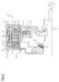
- Figures 1a and 1b show a dual clutch system 1 with an outer coupling unit 2 and an inner coupling unit 3.
- the outer coupling unit 2 and the inner Coupling unit 3 are concentric with respect to a rotation axis 4 of the dual clutch system 1 is arranged.
- the outer coupling unit 2 comprises an outer plate carrier 5, which rotatably connected to a drive flange 6 is. Furthermore, the outer clutch unit 2 an inner plate carrier 7. Between the outer plate carrier 5 and the inner plate carrier 7 is a Reiblamellenan onion 8 arranged.
- the friction disk assembly 8 has outer friction plates 9 and inner friction plates 10, the in each case in the direction of the axis of rotation 4 alternately one behind the other are arranged horizontally.
- the outer friction plates 9 rotatably with the outer plate carrier 5 and the inner Reiblamellen 10 rotatably connected to the inner plate carrier 7.
- the inner coupling unit 3 has an outer plate carrier 11 and an inner plate carrier 12. Between the outer plate carrier 11 and the inner plate carrier 12th a friction disc arrangement 13 is arranged.
- the agents according to the invention by which the amount of the Reiblamellenan Aunt 8 surrounding cooling medium in dependence is adjustable by the speed of the friction disk assembly 8, be in the present embodiment by a drum 14 and by an outlet 15 and an inlet device 16 formed.
- the drum 14 includes a portion of the outer disc carrier 5 (jacket and annular portion of the front side), and a portion of the drive flange 6 (annular Section), so that the Reiblamellenan Aunt 8 encompassing Cavity is created, which is in the radial direction essentially between outer plate carrier 5 and inner Plate carrier 7 of the outer coupling unit 2, not but extends into the region of the inner clutch unit 3.
- the outlet 15 consists of several outlet openings 17a and several overflow openings 18, each arranged on the same radius with respect to the axis of rotation 4 are.
- the outlet openings 17a are equal to each other spaced apart, wherein in the present embodiment six Outlet openings 17a and six overflow openings 18 are provided are one of each of which is visible.
- the outlet openings 17a as throttles 17a trained.
- the outlet openings 17a in Area of the outer radius of the Reiblamellenan angel arranged.
- the overflow openings 18 are closer in the radial direction the rotation axis 4 arranged as the outlet openings 17a.
- FIG. 1a shows the dual clutch system 1 at lower Speed, d. H. at a speed of less than 2200 rpm.
- the inlet device 16 and the outlet openings 17a and the overflow openings 18 of the outlet 15 so matched, that at low speeds when reaching the level the overflow openings 18, the largest proportion of the supplied Cooling medium 19 led away over the overflow openings 18 is, so that the torus of cooling medium 20 in the radial Direction only between the outer radius of the Reiblamellenan Aunt 8 and the overflow openings 18 extends.
- the vote between outlet 15 and inlet 16 takes place in the present embodiment on the size of Cross sections of the outlet openings 17a and the overflow openings 18, on the number of outlet openings 17 a and Overflow openings 18 and the amount of the inlet device 16 supplied cooling medium 19.
- the friction lamellae has the 8 completely enveloping at low speed Torus 20 almost completely degraded at high speed, so that only one in the radial direction between the outer Radius of the outer disc carrier 5 and the outlet openings 17a extending oil ring 21 is present, the Reiblamellenan ever 8 does not surround.
- FIG. 2a shows the system 1 at low speed
- Figure 2b shows the system 1 at high Number of revolutions.
- the outlet openings are not as throttles 17a, but as apertures 17b, d. H. as throttles with conical Cross section, formed.
- throttle openings 18 could through Be replaced apertures.
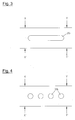
- the openings in the plate carrier 7 can as slots 31 a (corresponding to FIG. 3) as bores 31b (corresponding to FIG 4) or be formed in any other way.
- FIG. 5 shows a fifth embodiment of the invention in sections in longitudinal section. How out FIG. 5 reveals the dual-clutch system 1 the known from the figure 1 outer and inner coupling units 2 and 3 on.
- the outer coupling unit 2 has an outer plate carrier 22 and the drive flange 6 known from FIG on. Furthermore, a drum 23 is provided which the outer plate carrier 22 and the drive flange 6 at least partially embraces in such a way that the Reiblamellenan Aunt 8 is completely received in the drum 23.
- the drum 23 is as to the outer plate carrier 22 and to the drive flange 6 executed separate component. in this connection the drum 23 is rotationally fixed to the outer plate carrier 22nd and the drive flange 6 connected.
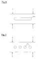
- the outer plate carrier 22 has several on its coat substantially over the entire length of the outer disc carrier 22 extending slit-like recesses 24a ( Figure 6). In similar Way also has the inner plate carrier 7 slit-like Recesses 31a, as z. B. shown in the figure 3 are.
- slot-like recesses 24 a, 31 a much of the Surface of the shell of the outer or inner disc carrier 22, 7 is, on the inlet means 16 inflowing Cooling medium 19 not through the outer and inner disc carrier 22, 7 collected, but flows substantially through the slot-like recesses 24a, 31a and is caught by the drum 23.
- the drum 23 further has outlet openings 25 and overflow openings 26, which are exemplified as chokes are.
- the outlet openings 25 are in the area of the outer Radius of the drum 23 is arranged.
- the overflow openings 26 are in the range of the inner radius of the outer Reiblamellenan extract 2 arranged.
- connection openings 28, 29, 30 is a circulation of the coolant within the pot, allowing heat exchange is further improved (including the other embodiments Of course, in appropriate Be designed manner).
- the circulation is driven by the pumping action of the grooved lamella, which is the coolant tend to exude to the outside (see dashed arrows 32).
- FIG. 5 shows the dual-clutch system at low speed, so that the cooling medium 19 a the Reiblamellenan Aunt 8 surrounding torus 27 of cooling medium 19 forms. From the supplied Cooling medium 19 is, analogous to Figure 1a, the majority the dissipated cooling medium 19 via the overflow openings 26th led away.
- FIG. 8 shows the course of the axial forces which are dependent on from the speed to a clutch housing of a conventional one Coupling system with closed cooling act.
- FIG. 9 shows the course of the axial force and the course the inner radius of the torus of cooling medium in a coupling system with a device according to the invention for cooling a Reiblamellenan Aunt according to Figures 1, 2 or 5th
- the inner Radius is smaller than the radial distance of the overflow openings from the axis of rotation.
- the entire flows Cooling medium only over the outlet openings.
- the inner radius of the torus increases from cooling medium the pressure in the area of the outer radius of the outer disk carrier remains constant and the pressure distribution accordingly gets steeper.
- the axially applied pressure surface is smaller and thus the effective axial forces decrease.
- the axial force is at 6000 rpm. only 200 N.
- Figure 10 shows a seventh embodiment of an inventive Device for cooling a friction disk arrangement. This device is designed almost identical, as that according to the fifth embodiment according to FIG. 5.
- the outlet opening is in contrast to the embodiment according to the figure 5 additionally with a speed-dependent outlet fitted.
- the speed-dependent outlet device is in the present embodiment as a so-called pendulum slider 33 trained.
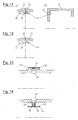
- FIG. 11 shows a detailed view of this pendulum slider.
- FIG. 11 b shows the drum 23 of the dual-clutch system 1 according to the figure 10 in axial section.
- FIG. 11 a shows a radial section in FIG Top view of the drum 23 according to the invention, the outlet opening 25 concealing pendulum slide 33.
- FIG. 12 is a detail view of an eighth embodiment a device according to the invention for cooling a Remove friction disk assembly.
- the pendulum slider as he used in the embodiment according to the figure 10 was, by another variant of a pendulum slide 33 replaced with integrated spring element.
- the pendulum slider 33 corresponding to FIG. 12 is in cross section dumbbell-shaped. One end is the pendulum slider 33 via a fixation (riveting, welding, gluing or the like) on the inner end surface of the drum 23 attached. On the other end, the pendulum slide 33 covers at low speeds, as shown in Figure 12, the Outlet opening 25.
- the dumbbell-shaped figure of the pendulum slider 33 has the result that the outlet opening 25 overlapping Side of the pendulum slide 33 in the manner of a spring joint 36 with the attached to the drum 23 side of the spring element 33 is articulated. As the speed increases, the outlet opening becomes 25 increasingly against the spring action of the spring joint 36 Approved.
- FIG. 13 shows a detailed view of a ninth embodiment a device according to the invention for cooling a friction plate assembly.
- the pendulum slide according to the figures 10 to 12 replaced by a so-called externally spring-loaded valve 38.
- the Valve head of the valve 38 is through an outlet opening 25 cross-bracket 40 and held by means of a as Coil spring 39 formed spring element at low Speeds held against the outlet opening 25.
- Coil spring 39 formed spring element at low Speeds held against the outlet opening 25.
- This valve body is characterized with increasing pressure and with increasing own Centrifugal force and thus increasing force against the spring force of the spring element 39 is opened, so that the outlet opening 25 is increasingly released with increasing speed and allowing drainage of oil.
- FIG. 14 shows a detailed view of a tenth embodiment a device according to the invention for cooling a Friction disc.
- this is externally sprung valve 38 according to the figure 13 by a internally sprung valve 41 replaced.
- the valve body of the valve 41 sits again as in the example described above on the outer wall of the drum 23.
- a plunger 56 which the Outlet opening 25 centrally penetrated.
- End wearing this Plunger 56 a bracket 43.
- the bracket 43 carries in turn in the direction aligned with the inner wall of the end face of the drum 23 Feet 44.
- the inside of the temple 43 by means of a spring element 39 against the inner wall of the Front side of the drum 23, the valve 41 in the closed position supported on a long-term basis.
- FIGS 15 and 16 show detailed views of an eleventh embodiment a device according to the invention for cooling a friction plate assembly. It is an internally sprung Valve provided as a speed-dependent outlet. The suspension of the internally sprung valve 41 is by means of a Leaf spring 42 realized, which is essentially in the axial Direction extends.
- valve body of the valve 41 Similar to the embodiment described above sits the valve body of the valve 41 at low speeds on the outside of the drum 23, the outlet opening 25 closing on.
- the inner end face of the valve body carries in turn, a plunger 45, which the opening 25 centrally interspersed and the other end carries a leaf spring 42.
- the leaf spring 42 is in the direction of the inner wall of the Curved face of the drum 23 and holds the valve body the valve 41 by its spring force at low speeds in its closed position.
- FIG. 17 shows a detailed view of another twelfth Embodiment of an inventive device for Cooling a Reiblamellenan Aunt. Similar to the above described embodiment is an internally sprung Valve 41 is provided as a speed-dependent outlet. The suspension of the internally sprung valve 41 is in turn realized by means of a leaf spring 42. In difference to the embodiment described above is here the Leaf spring 42, however, oriented in the circumferential direction, whereby a short axial length results. Incidentally, a largely identical valve behavior achieved.
- FIG. 18 shows a detailed view of a thirteenth embodiment a device according to the invention for cooling a friction plate assembly. It is an internally sprung Valve 46 is provided as a speed-dependent outlet. The suspension of the internally sprung valve 46 is now by means of realized a bending spring 48.
- FIG. 19 shows a detailed view of a fourteenth embodiment a device according to the invention for cooling a friction plate assembly. It is an exterior suspension Valve 51 is provided as a speed-dependent outlet device. The suspension of the externally sprung valve 51 is by means of a Bending spring 53 realized.
- FIG. 19a shows the device in longitudinal section
- the figure 19b shows the device in cross section.
- the valve according to FIG. 19 comprises a bending spring 53, which is at one end attached to the drum 23 (attachment 55). At the other end, the spiral spring 53 carries a Seal plate 52, which the outlet opening 25 at low Speeds, as shown in Figures 19, from the outside closes.
Landscapes
- Engineering & Computer Science (AREA)
- General Engineering & Computer Science (AREA)
- Mechanical Engineering (AREA)
- Mechanical Operated Clutches (AREA)
- Hydraulic Clutches, Magnetic Clutches, Fluid Clutches, And Fluid Joints (AREA)
Abstract
Description
- Figur 1
- ein erstes Ausführungsbeispiel einer erfindungsgemäßen
Vorrichtung zum Kühlen einer Reiblamellenanordnung,
- a) System bei niedriger Drehzahl
- b) System bei hoher Drehzahl
- Figur 2
- ein zweites Ausführungsbeispiel einer erfindungsgemäßen
Vorrichtung zum Kühlen einer Reiblamellenanordnung,
- a) System bei niedriger Drehzahl
- b) System bei hoher Drehzahl
- Figur 3
- eine Detailansicht eines dritten Ausführungsbeispiels
entsprechend dem ersten Ausführungsbeispiel
gemäß der Figur 1 oder entsprechend dem
zweiten Ausführungsbeispiel gemäß der Figur 2 im
Schnitt X-Y.
Die Verbindungsöffnungen sind als Schlitze ausgebildet, - Figur 4
- eine Detailansicht eines vierten Ausführungsbeispiels
entsprechend dem ersten Ausführungsbeispiel
gemäß der Figur 1 oder entsprechend dem
zweiten Ausführungsbeispiel gemäß der Figur 2 im
Schnitt X-Y.
Die Verbindungsöffnungen sind als Bohrungen ausgebildet, - Figur 5
- ein fünftes Ausführungsbeispiel einer erfindungsgemäßen
Vorrichtung zum Kühlen einer Reiblamellenanordnung
System bei niedriger Drehzahl, - Figur 6
- Detailansicht des fünften Ausführungsbeispiels
gemäß der Figur 5 im Schnitt X-Y.
Die Öffnungen im äußeren Lamellenträger sind als
Schlitze ausgebildet, - Figur 7
- Detailansicht eines sechsten Ausführungsbeispiels
entsprechend der Figur 5 im Schnitt A-B.
Die Öffnungen im inneren Lamellenträger sind als Bohrungen ausgebildet, - Figur 8
- Axialkraft eines Öltorus einer geschlossenen Kühlung gemäß dem Stand der Technik,
- Figur 9
- Axialkraft und innerer Radius von erfindungsgemäßen Vorrichtungen zum Kühlen einer Reiblamellenanordnung entsprechend den Figuren 1, 2 und 5.
- Figur 10
- ein siebentes Ausführungsbeispiel einer
erfindungsgemäßen Vorrichtung zum Kühlen einer
Reiblamellenanordnung. Dargestellt ist das System bei
niedriger Drehzahl.
Es ist eine als Pendelschieber ausgebildete drehzahlabhängige Auslasseinrichtung vorgesehen. - Figur 11
- Detailansicht des Pendelschiebers gemäß der Figur 10.
- Figur 12
- Detailansicht eines achten Ausführungsbeispiels
einer erfindungsgemäßen Vorrichtung zum Kühlen
einer Reiblamellenanordnung.
Der Pendelschieber entsprechend Figur 10 ist durch eine andere Ausführungsvariante eines Pendelschiebers mit integriertem Federelement ersetzt. - Figur 13
- Detailansicht eines neunten Ausführungsbeispiels
einer erfindungsgemäßen Vorrichtung zum Kühlen
einer Reiblamellenanordnung.
Der Pendelschieber entsprechend Figur 10 ist durch ein außen gefedertes Ventil ersetzt. - Figur 14
- Detailansicht eines zehnten Ausführungsbeispiels
einer erfindungsgemäßen Vorrichtung zum Kühlen
einer Reiblamellenanordnung.
Das außen gefederte Ventil entsprechend Figur 13 ist durch ein innen gefedertes Ventil ersetzt. - Figur 15
- Detailansicht eines elfen Ausführungsbeispiels
einer erfindungsgemäßen Vorrichtung zum Kühlen
einer Reiblamellenanordnung.
Es ist ein innen gefedertes Ventil als drehzahlabhängige Auslasseinrichtung vorgesehen. Die Federung des innen gefederten Ventils ist mittels einer Blattfeder realisiert. - Figur 16
- Detailansicht des elften Ausführungsbeispiels
einer erfindungsgemäßen Vorrichtung zum Kühlen
einer Reiblamellenanordnung.
Es ist ein innen gefedertes Ventil als drehzahlabhängige Auslasseinrichtung vorgesehen. Die Federung des innen gefederten Ventils ist mittels einer Blattfeder realisiert. - Figur 17
- Detailansicht eines zwölften Ausführungsbeispiels
einer erfindungsgemäßen Vorrichtung zum Kühlen
einer Reiblamellenanordnung.
Es ist ein innen gefedertes Ventil als drehzahlabhängige Auslasseinrichtung vorgesehen. Die Federung des innen gefederten Ventils ist mittels einer Blattfeder realisiert. - Figur 18
- Detailansicht eines dreizehnten Ausführungsbeispiels
einer erfindungsgemäßen Vorrichtung zum
Kühlen einer Reiblamellenanordnung.
Es ist ein innen gefedertes Ventil als drehzahlabhängige Auslasseinrichtung vorgesehen. Die Federung des innen gefederten Ventils ist mittels einer Biegefeder realisiert. - Figur 19
- Detailansicht eines vierzehnten Ausführungsbeispiels
einer erfindungsgemäßen Vorrichtung zum
Kühlen einer Reiblamellenanordnung.
Es ist ein außen gefedertes Ventil als drehzahlabhängige Auslasseinrichtung vorgesehen. Die Federung des außen gefederten Ventils ist mittels einer Biegefeder realisiert.- a) Längsschnitt
- b) Querschnitt
- 1
- Doppelkupplungssystem
- 2
- äußere Kupplungseinheit
- 3
- innere Kupplungseinheit
- 4
- Drehachse
- 5
- äußerer Lamellenträger
- 6
- Antriebsflansch
- 7
- innerer Lamellenträger
- 8
- Reiblamellenanordnung
- 9
- äußere Reiblamellen
- 10
- innere Reiblamellen
- 11
- äußerer Lamellenträger
- 12
- innerer Lamellenträger
- 13
- Reiblamellenanordnung
- 14
- Trommel
- 15
- Auslasseinrichtung
- 16
- Einlasseinrichtung
- 17
- Auslassöffnung
- 18
- Überlauföffnung
- 19
- Kühlmedium
- 20
- Torus (Kühlmedium)
- 21
- flacher Ring (Kühlmedium)
- 22
- äußerer Lamellenträger
- 23
- Trommel
- 24a
- Schlitz
- 24b
- Bohrung
- 25
- Auslassöffnung
- 26
- Überlauföffnung
- 27
- Torus (Kühlmedium)
- 28
- Verbindungsöffnung
- 29
- Verbindungsöffnung
- 30
- Verbindungsöffnung
- 31a
- Schlitz
- 31b
- Bohrung
- 32
- Kühlmittelfluss
- 33
- Pendelschieber
- 34
- Federelement (Schraubenfeder)
- 35
- Gelenk
- 36
- Federgelenk
- 37
- Fixierung
- 38
- Ventil
- 39
- Federelement (Schraubenfeder)
- 40
- Bügel
- 41
- Ventil
- 42
- Federelement (Blattfeder)
- 43
- Bügel
- 44
- Füßchen
- 45
- Stößel
- 46
- Ventil
- 47
- Stößel
- 48
- Federelement (Biegefeder)
- 49
- Füßchen
- 50
- Befestigung
- 51
- Ventil
- 52
- Dichtungsteller
- 53
- Federelement (Biegefeder)
- 54
- Bügel
- 55
- Befestigung
- 56
- Stößel
Claims (33)
- Vorrichtung zum Kühlen einer in einem Drehzahlbereich drehbaren Reiblamellenanordnung (8) einer Kupplung (1), mittels eines Kühlmediums (19),
dadurch gekennzeichnet, dass die Vorrichtung Mittel aufweist, durch welche die Menge des die Reiblamellenanordnung (8) umgebenden Kühlmediums (19) in Abhängigkeit von der Drehzahl der Reiblamellenanordnung (8) einstellbar ist. - Vorrichtung nach Anspruch 1,
dadurch gekennzeichnet, dass die Mittel dergestalt sind, dass das Kühlmedium (19) bei niederen Drehzahlen einen die Reiblamellenanordnung (8) umgebenden Torus (20, 27) bildet, und dass die Reiblamellenanordnung (8) bei hohen Drehzahlen im wesentlichen nicht vom Kühlmedium (19) umgeben ist. - Vorrichtung nach einem der Ansprüche 1 oder 2,
dadurch gekennzeichnet, dass die Menge des die Reiblamellenanordnung (8) umgebenden Kühlmediums (19) durch die Wechselwirkung zwischen den Mitteln und der auf das Kühlmedium (19) einwirkenden Zentrifugalkraft einstellbar ist. - Vorrichtung nach einem der Ansprüche 1 bis 3,
dadurch gekennzeichnet, dass bei PKW-Benzin-Motoren niedere Drehzahlen weniger als 25-40% der maximalen Betriebsdrehzahl und hohe Drehzahlen mehr als 25-40% der maximalen Betriebsdrehzahl betragen bzw. dass bei PKW-Diesel-Motoren niedere Drehzahlen weniger als 40-55% der maximalen Betriebsdrehzahl (nmax) betragen und hohe Drehzahlen mehr als 40-55% der maximalen Betriebsdrehzahl (nmax) betragen. - Vorrichtung nach einem der Ansprüche 1 bis 4,
dadurch gekennzeichnet, dass die Mittel eine die Reiblamellenanordnung (8) aufnehmende Trommel (14, 23) sowie eine Einlasseinrichtung (16) und eine Auslasseinrichtung (15) umfassen, wobei das Kühlmedium (19) über die Einlasseinrichtung (16) der Trommel (14, 23) zuführbar und über die Auslasseinrichtung (15) aus der Trommel (14, 23) wegführbar ist. - Vorrichtung nach einem der Ansprüche 1 bis 5,
dadurch gekennzeichnet, dass die Reiblamellenanordnung (8) äußere (9) und innere Reiblamellen (10) hat, und dass die Trommel (14, 23) drehfest mit den äußeren (9) oder den inneren Reiblamellen (10) verbundenen ist. - Vorrichtung nach einem der Ansprüche 5 oder 6,
dadurch gekennzeichnet, dass die Auslasseinrichtung (15) Auslassöffnungen (17a, 17b, 25) in der Trommel (14, 23) und die Einlasseinrichtung (16) Einlassöffnungen und / oder eine Pumpe aufweist. - Vorrichtung nach Anspruch 7,
dadurch gekennzeichnet, dass die Querschnitte der Auslassöffnungen (17a, 17b, 25) und die Querschnitte der Einlassöffnungen und / oder die Förderleistung der Pumpe aufeinander angestimmt sind. - Vorrichtung nach Anspruch 8,
dadurch gekennzeichnet, dass die Querschnitte der Auslassöffnungen (17a, 17b, 25) und / oder die Querschnitte der Einlassöffnungen drehzahlabhängig veränderbar sind. - Vorrichtung nach Anspruch 7, 8 oder 9,
dadurch gekennzeichnet, dass Ventileinrichtungen (33, 38, 51, 41, 46) vorgesehen sind, mittels derer der Durchfluss durch die Querschnitte der Auslassöffnungen (17, 25) und/oder der Durchfluss durch die Querschnitte der Einlassöffnungen (16) regelbar oder steuerbar ist. - Vorrichtung nach Anspruch 10,
dadurch gekennzeichnet, dass die Ventileinrichtungen als Pendelschieber (33) und/oder als außen gefederte Ventile (38, 51) und/oder als innen gefederte Ventile (41, 46) ausgebildet sind. - Vorrichtung nach einem der Ansprüche 5 bis 11,
dadurch gekennzeichnet, dass die Trommel (14, 23) konzentrisch zu der die Reiblamellenanordnung lagernden Drehachse (4) angeordnet ist, und deren Stirnseiten jeweils durch Ringe gebildet werden, die sich in radialer Richtung zumindest im Bereich der Reiblamellen (9, 10) der Reiblamellenanordnung (8) erstrecken, so dass die Trommel (14, 23) einen zumindest die Reiblamellen (9, 10) umgreifenden Hohlraum bildet. - Vorrichtung nach Anspruch 12,
dadurch gekennzeichnet, dass die Trommel (14) durch einen Abschnitt des Außenlamellenträgers (5) und durch einen Abschnitt des damit drehfest verbundenen Antriebflansches (6) gebildet wird. - Vorrichtung nach Anspruch 12,
dadurch gekennzeichnet, dass die Trommel (23) als ein den Außenlamellenträger (22) und den Antriebsflansch (6) zumindest abschnittweise umgreifendes separates Bauteil ausgebildet ist. - Vorrichtung nach einem der Ansprüche 7 bis 14,
dadurch gekennzeichnet, dass die Auslassöffnungen (17a, 17b, 25) radial außerhalb oder im Bereich des äußeren Radius der Reiblamellenanordnung (8) angeordnet sind. - Vorrichtung nach einem der Ansprüche 7 bis 15,
dadurch gekennzeichnet, dass die Auslassöffnungen (17a, 17b) im Bereich des äußeren Radius der inneren Reiblamellen angeordnet sind. - Vorrichtung nach einem der Ansprüche 7 bis 16,
dadurch gekennzeichnet, dass die Auslassöffnungen (17a, 17b, 25) als Drosseln (17a, 25) oder Blenden (17b) ausgebildet sind. - Vorrichtung nach einem der Ansprüche 7 bis 17,
dadurch gekennzeichnet, dass zwischen einer und zwanzig Auslassöffnungen (17a, 17b, 25), insbesondere zwischen vier und acht Auslassöffnungen (17a, 17b, 25) vorhanden sind. - Vorrichtung nach einem der Ansprüche 7 bis 18,
dadurch gekennzeichnet, dass die Auslasseinrichtung (15) Überlauföffnungen (18, 26) aufweist, die in radialer Richtung näher an der Drehachse (4) angeordnet sind als die Auslassöffnungen (17a, 17b, 25). - Vorrichtung nach Anspruch 19,
dadurch gekennzeichnet, dass die Überlauföffnungen (18, 26) an zumindest einem der Ringe der Trommel (14, 23) angeordnet sind. - Vorrichtung nach einem der Ansprüche 19 oder 20,
dadurch gekennzeichnet, dass alle Überlauföffnungen (18, 26) und / oder alle Auslassöffnungen (17a, 17b, 25) jeweils auf dem gleichen Radius in Bezug zur Drehachse (4) angeordnet sind. - Vorrichtung nach einem der Ansprüche 19 bis 21,
dadurch gekennzeichnet, dass die Überlauföffnungen (18, 26) im Bereich des inneren Radius der Reiblamellenanordnung (8) angeordnet sind. - Vorrichtung nach einem der Ansprüche 19 bis 22,
dadurch gekennzeichnet, dass zwischen einer und zwanzig Überlauföffnungen (18, 26), insbesondere zwischen vier und acht Überlauföffnungen (18, 26) vorgesehen sind. - Vorrichtung nach einem der Ansprüche 19 bis 23,
dadurch gekennzeichnet, dass die Auslassöffnungen (17a, 17b, 25) und die Überlauföffnungen (18, 26) derart aufeinander abgestimmt sind, dass bei niederen Drehzahlen ein großer Teil des zugeführten Kühlmediums (19), insbesondere 60% bis 100%, über die Überlauföffnungen (18, 26) wegführbar ist, und dass bei hohen Drehzahlen das gesamte zugeführte Kühlmedium (19) über die Auslassöffnungen (17a,17b) wegführbar ist. - Vorrichtung nach einem der Ansprüche 19 bis 24,
dadurch gekennzeichnet, dass die Querschnitte der Überlauföffnungen (18, 26) drehzahlabhängig veränderbar sind. - Vorrichtung nach einem der Ansprüche 19 bis 25,
dadurch gekennzeichnet, dass Ventileinrichtungen vorgesehen sind, mittels derer der Durchfluss durch die Querschnitte der Überlauföffnungen (18, 26) regelbar oder steuerbar ist. - Vorrichtung nach Anspruch 26,
dadurch gekennzeichnet, dass die Ventileinrichtungen als Pendelschieber und/oder außen gefederte Ventile und/oder innen gefederte Ventile ausgebildet sind. - Vorrichtung nach einem der Ansprüche 1 bis 27,
dadurch gekennzeichnet, dass der Trommel (14, 23) ein Kühlmediumfluss von 3 bis 15 Liter pro Minute, insbesondere von 4 bis 7 Liter pro Minute, zuführbar ist. - Verwendung einer Vorrichtung zum Kühlen einer Reiblamellenanordnung nach einem der Ansprüche 1 bis 28 in einer Doppelkupplung.
- Verwendung nach Anspruch 29,
dadurch gekennzeichnet, dass die Doppelkupplung (1) eine konzentrische Doppelkupplung ist, bei der die Reiblamellen der einen Kupplung radial kleiner sind als die Reiblamellen der anderen Kupplung. - Verwendung nach einem der Ansprüche 29 oder 30,
dadurch gekennzeichnet, dass die Vorrichtung zur Kühlung Bestandteil einer Anfahrkupplung ist. - Verfahren zum Kühlen einer Reiblamellenanordnung (8) einer Kupplung (1) mittels eines Kühlmediums (19), bei dem bei niederen Drehzahlen die Menge des Kühlmediums (19) so eingestellt wird, dass das Kühlmedium (19) die Reiblamellenanordnung (8) im wesentlichen vollständig umgibt, und dass bei hohen Drehzahlen die Menge des Kühlmediums (19) so eingestellt wird, dass die Reiblamellenanordnung (8) im wesentlichen nicht von dem Kühlmedium (19) umgeben ist.
- Verfahren nach Anspruch 32,
dadurch gekennzeichnet, dass die Menge des die Reiblamellenanordnung (8) umgebenden Kühlmediums (19) in Abhängigkeit des der Reiblamellenanordnung (8) zugeführten und von dieser weggeführten Kühlmediums (19) eingestellt wird, wobei die Menge des weggeführten Kühlmediums (19) mit durch die auf das Kühlmedium (19) und gegebenenfalls Ventile (33, 38, 41, 46, 51) wirkende Zentrifugalkraft beeinflusst wird.
Priority Applications (4)
| Application Number | Priority Date | Filing Date | Title |
|---|---|---|---|
| DE50304883T DE50304883D1 (de) | 2003-12-13 | 2003-12-13 | Vorrichtung zum Kühlen einer Reiblamellenanordnung einer Kupplung |
| EP20030028790 EP1541887B1 (de) | 2003-12-13 | 2003-12-13 | Vorrichtung zum Kühlen einer Reiblamellenanordnung einer Kupplung |
| DE200460006361 DE602004006361T2 (de) | 2003-12-13 | 2004-06-03 | Doppelkupplungsübertragungselement für ein hybrides Fahrzeugsantriebssystem, Verfahren für den Aufbau des Elementes und Motorfahrzeug mit einem solchen Element |
| EP04013102A EP1541401B1 (de) | 2003-12-13 | 2004-06-03 | Doppelkupplungsübertragungselement für ein hybrides Fahrzeugsantriebssystem, Verfahren für den Aufbau des Elementes und Motorfahrzeug mit einem solchen Element |
Applications Claiming Priority (1)
| Application Number | Priority Date | Filing Date | Title |
|---|---|---|---|
| EP20030028790 EP1541887B1 (de) | 2003-12-13 | 2003-12-13 | Vorrichtung zum Kühlen einer Reiblamellenanordnung einer Kupplung |
Publications (2)
| Publication Number | Publication Date |
|---|---|
| EP1541887A1 true EP1541887A1 (de) | 2005-06-15 |
| EP1541887B1 EP1541887B1 (de) | 2006-08-30 |
Family
ID=34486209
Family Applications (1)
| Application Number | Title | Priority Date | Filing Date |
|---|---|---|---|
| EP20030028790 Expired - Lifetime EP1541887B1 (de) | 2003-12-13 | 2003-12-13 | Vorrichtung zum Kühlen einer Reiblamellenanordnung einer Kupplung |
Country Status (2)
| Country | Link |
|---|---|
| EP (1) | EP1541887B1 (de) |
| DE (2) | DE50304883D1 (de) |
Cited By (4)
| Publication number | Priority date | Publication date | Assignee | Title |
|---|---|---|---|---|
| DE102008001358A1 (de) * | 2008-04-24 | 2009-10-29 | Zf Friedrichshafen Ag | Kupplungsanordnung, insbesondere für den Antriebsstrang eines Fahrzeugs |
| WO2012175060A1 (de) * | 2011-06-21 | 2012-12-27 | Schaeffler Technologies AG & Co. KG | Drehmomentübertragungseinrichtung |
| US8556051B2 (en) | 2006-11-06 | 2013-10-15 | Schaeffler Technologies AG & Co. KG | Clutch assembly and force transmission device with a clutch assembly |
| CN115823136A (zh) * | 2022-12-06 | 2023-03-21 | 江麓机电集团有限公司 | 湿式离合器及用于湿式离合器摩擦片逐片均匀分离的机构 |
Families Citing this family (5)
| Publication number | Priority date | Publication date | Assignee | Title |
|---|---|---|---|---|
| DE102011009419B4 (de) * | 2010-02-03 | 2025-02-20 | Borgwarner Inc. | Mehrfachkupplungseinrichtung und Antriebsstrang mit einer solchen Mehrfachkupplungseinrichtung |
| DE102010061062B4 (de) | 2010-12-07 | 2023-08-10 | Dr. Ing. H.C. F. Porsche Aktiengesellschaft | Baukastensystem |
| DE102016214514A1 (de) * | 2016-08-05 | 2018-02-08 | Schaeffler Technologies AG & Co. KG | Hybridmodul mit vollintegrierten Trenn- und Doppelkupplungen |
| CN113103862B (zh) * | 2021-04-10 | 2022-08-05 | 重庆工程职业技术学院 | 一种履带式越障车 |
| DE102022102304B3 (de) | 2022-02-01 | 2023-05-11 | Schaeffler Technologies AG & Co. KG | Bauraumsparendes Kupplungssystem |
Citations (4)
| Publication number | Priority date | Publication date | Assignee | Title |
|---|---|---|---|---|
| GB1290974A (de) * | 1969-09-05 | 1972-09-27 | ||
| US3964587A (en) * | 1973-08-02 | 1976-06-22 | Borg-Warner Corporation | Control valve for a wet clutch |
| EP0447019A2 (de) * | 1990-03-13 | 1991-09-18 | Borg-Warner Automotive Transmission And Engine Components Corporation | Rillenmuster für viskose Hochleistungspumpwirkung in einer Nasskupplung |
| DE10151632A1 (de) * | 2001-10-19 | 2003-05-08 | Zf Sachs Ag | Kupplungsanordnung |
-
2003
- 2003-12-13 DE DE50304883T patent/DE50304883D1/de not_active Expired - Lifetime
- 2003-12-13 EP EP20030028790 patent/EP1541887B1/de not_active Expired - Lifetime
-
2004
- 2004-06-03 DE DE200460006361 patent/DE602004006361T2/de not_active Expired - Lifetime
Patent Citations (4)
| Publication number | Priority date | Publication date | Assignee | Title |
|---|---|---|---|---|
| GB1290974A (de) * | 1969-09-05 | 1972-09-27 | ||
| US3964587A (en) * | 1973-08-02 | 1976-06-22 | Borg-Warner Corporation | Control valve for a wet clutch |
| EP0447019A2 (de) * | 1990-03-13 | 1991-09-18 | Borg-Warner Automotive Transmission And Engine Components Corporation | Rillenmuster für viskose Hochleistungspumpwirkung in einer Nasskupplung |
| DE10151632A1 (de) * | 2001-10-19 | 2003-05-08 | Zf Sachs Ag | Kupplungsanordnung |
Cited By (8)
| Publication number | Priority date | Publication date | Assignee | Title |
|---|---|---|---|---|
| US8556051B2 (en) | 2006-11-06 | 2013-10-15 | Schaeffler Technologies AG & Co. KG | Clutch assembly and force transmission device with a clutch assembly |
| DE112007002505B4 (de) * | 2006-11-06 | 2017-01-12 | Schaeffler Technologies AG & Co. KG | Kupplungsanordnung und Kraftübertragungseinrichtung mit einer Kupplungsanordnung |
| DE112007002505C5 (de) * | 2006-11-06 | 2024-04-18 | Schaeffler Technologies AG & Co. KG | Kupplungsanordnung und Kraftübertragungseinrichtung mit einer Kupplungsanordnung |
| DE102008001358A1 (de) * | 2008-04-24 | 2009-10-29 | Zf Friedrichshafen Ag | Kupplungsanordnung, insbesondere für den Antriebsstrang eines Fahrzeugs |
| WO2012175060A1 (de) * | 2011-06-21 | 2012-12-27 | Schaeffler Technologies AG & Co. KG | Drehmomentübertragungseinrichtung |
| CN103620252A (zh) * | 2011-06-21 | 2014-03-05 | 舍弗勒技术股份两合公司 | 转矩传递装置 |
| CN103620252B (zh) * | 2011-06-21 | 2016-04-06 | 舍弗勒技术股份两合公司 | 转矩传递装置 |
| CN115823136A (zh) * | 2022-12-06 | 2023-03-21 | 江麓机电集团有限公司 | 湿式离合器及用于湿式离合器摩擦片逐片均匀分离的机构 |
Also Published As
| Publication number | Publication date |
|---|---|
| DE50304883D1 (de) | 2006-10-12 |
| DE602004006361T2 (de) | 2008-02-21 |
| DE602004006361D1 (de) | 2007-06-21 |
| EP1541887B1 (de) | 2006-08-30 |
Similar Documents
| Publication | Publication Date | Title |
|---|---|---|
| DE69332179T2 (de) | Differential mit begrenztem Schlupf. | |
| DE102009002481B4 (de) | Antriebssystem mit Drehmomentübertragungsanordnung und hydrodynamische Kopplungsanordnung | |
| DE60026062T2 (de) | Freilaufkupplungseinrichtung | |
| DE3927153C2 (de) | Temperaturgesteuerte Ventilatorflüssigkeitsreibungskupplung | |
| DE102016118699A1 (de) | Variables Leitblech zur Ölreduzierung beim Zahneingriff | |
| DE10338432A1 (de) | Flüssigkeitsreibkupplung | |
| DE102009039223A1 (de) | Doppelkupplungsanordnung für ein Getriebe mit zwei Eingangswellen | |
| DE102011120776A1 (de) | Drehmomentwandler mit verriegelungskupplung | |
| DE102006034960B4 (de) | Kühlmittelpumpe für einen Kühlkreislauf einer Verbrennungskraftmaschine | |
| DE3717773C2 (de) | ||
| DE102009057070A1 (de) | Kolbenmaschine zum Einsatz als Vakuumpumpe für medizinische Zwecke | |
| DE102007017046A1 (de) | Hydrodynamische Drehmomentübertragungsvorrichtung und dafür verwendete Überbrückungsvorrichtung | |
| EP1857698A2 (de) | Kopplungsanordnung | |
| EP1541887B1 (de) | Vorrichtung zum Kühlen einer Reiblamellenanordnung einer Kupplung | |
| EP1438504B8 (de) | Hubkolbenmaschine mit einer schiebehülse | |
| DE602005000741T2 (de) | Hydraulisches Regelventil | |
| DE102019210037A1 (de) | Antriebsanordnung mit Schmiermittelreservoir | |
| DE4442451A1 (de) | Flüssigkeitsreibungskupplung | |
| DE102007026141A1 (de) | Drehmomentübertragungseinrichtung | |
| DE102014218555A1 (de) | Drehmomentwandlereinrichtung sowie Verfahren zum Regeln eines Flüssigkeitskreislaufs einer Drehmomentwandlereinrichtung | |
| DE10050729A1 (de) | Hydrodynamische Kopplungseinrichtung | |
| EP2598774A1 (de) | Torsionsschwingungsdämpfer | |
| DE102005031813A1 (de) | Dämpfungseinrichtung für einen Torsionsschwingungsdämpfer | |
| EP0279271B1 (de) | Flüssigkeitsreibungskupplung | |
| DE102019118079B4 (de) | Antriebseinheit mit Kühlmittelleitsystem zur Zuführung und Aufteilung eines Fluidstroms zwischen zwei Getriebeeingangswellen |
Legal Events
| Date | Code | Title | Description |
|---|---|---|---|
| PUAI | Public reference made under article 153(3) epc to a published international application that has entered the european phase |
Free format text: ORIGINAL CODE: 0009012 |
|
| 17P | Request for examination filed |
Effective date: 20040823 |
|
| AK | Designated contracting states |
Kind code of ref document: A1 Designated state(s): AT BE BG CH CY CZ DE DK EE ES FI FR GB GR HU IE IT LI LU MC NL PT RO SE SI SK TR |
|
| AX | Request for extension of the european patent |
Extension state: AL LT LV MK |
|
| GRAP | Despatch of communication of intention to grant a patent |
Free format text: ORIGINAL CODE: EPIDOSNIGR1 |
|
| RIN1 | Information on inventor provided before grant (corrected) |
Inventor name: HEINRICH, JOHANNES, DR. Inventor name: BAUER, KARL-HEINZ |
|
| GRAS | Grant fee paid |
Free format text: ORIGINAL CODE: EPIDOSNIGR3 |
|
| RAP1 | Party data changed (applicant data changed or rights of an application transferred) |
Owner name: BORGWARNER INC. |
|
| AKX | Designation fees paid |
Designated state(s): DE FR GB IT |
|
| GRAA | (expected) grant |
Free format text: ORIGINAL CODE: 0009210 |
|
| AK | Designated contracting states |
Kind code of ref document: B1 Designated state(s): DE FR GB IT |
|
| REG | Reference to a national code |
Ref country code: GB Ref legal event code: FG4D Free format text: NOT ENGLISH |
|
| REF | Corresponds to: |
Ref document number: 50304883 Country of ref document: DE Date of ref document: 20061012 Kind code of ref document: P |
|
| GBT | Gb: translation of ep patent filed (gb section 77(6)(a)/1977) |
Effective date: 20061018 |
|
| ET | Fr: translation filed | ||
| PLBE | No opposition filed within time limit |
Free format text: ORIGINAL CODE: 0009261 |
|
| STAA | Information on the status of an ep patent application or granted ep patent |
Free format text: STATUS: NO OPPOSITION FILED WITHIN TIME LIMIT |
|
| 26N | No opposition filed |
Effective date: 20070531 |
|
| PGFP | Annual fee paid to national office [announced via postgrant information from national office to epo] |
Ref country code: IT Payment date: 20081218 Year of fee payment: 6 |
|
| PGFP | Annual fee paid to national office [announced via postgrant information from national office to epo] |
Ref country code: GB Payment date: 20081110 Year of fee payment: 6 |
|
| GBPC | Gb: european patent ceased through non-payment of renewal fee |
Effective date: 20091213 |
|
| PG25 | Lapsed in a contracting state [announced via postgrant information from national office to epo] |
Ref country code: GB Free format text: LAPSE BECAUSE OF NON-PAYMENT OF DUE FEES Effective date: 20091213 |
|
| PG25 | Lapsed in a contracting state [announced via postgrant information from national office to epo] |
Ref country code: IT Free format text: LAPSE BECAUSE OF NON-PAYMENT OF DUE FEES Effective date: 20091213 |
|
| REG | Reference to a national code |
Ref country code: FR Ref legal event code: PLFP Year of fee payment: 13 |
|
| REG | Reference to a national code |
Ref country code: FR Ref legal event code: PLFP Year of fee payment: 14 |
|
| REG | Reference to a national code |
Ref country code: FR Ref legal event code: PLFP Year of fee payment: 15 |
|
| PGFP | Annual fee paid to national office [announced via postgrant information from national office to epo] |
Ref country code: FR Payment date: 20171120 Year of fee payment: 15 |
|
| PGFP | Annual fee paid to national office [announced via postgrant information from national office to epo] |
Ref country code: DE Payment date: 20171221 Year of fee payment: 15 |
|
| REG | Reference to a national code |
Ref country code: DE Ref legal event code: R119 Ref document number: 50304883 Country of ref document: DE |
|
| PG25 | Lapsed in a contracting state [announced via postgrant information from national office to epo] |
Ref country code: DE Free format text: LAPSE BECAUSE OF NON-PAYMENT OF DUE FEES Effective date: 20190702 Ref country code: FR Free format text: LAPSE BECAUSE OF NON-PAYMENT OF DUE FEES Effective date: 20181231 |