EP1541795A2 - Wechselbehälter zur Aufbewahrung von Wertdokumenten - Google Patents
Wechselbehälter zur Aufbewahrung von Wertdokumenten Download PDFInfo
- Publication number
- EP1541795A2 EP1541795A2 EP04026652A EP04026652A EP1541795A2 EP 1541795 A2 EP1541795 A2 EP 1541795A2 EP 04026652 A EP04026652 A EP 04026652A EP 04026652 A EP04026652 A EP 04026652A EP 1541795 A2 EP1541795 A2 EP 1541795A2
- Authority
- EP
- European Patent Office
- Prior art keywords
- container
- transponder
- document processing
- processing device
- interchangeable
- Prior art date
- Legal status (The legal status is an assumption and is not a legal conclusion. Google has not performed a legal analysis and makes no representation as to the accuracy of the status listed.)
- Withdrawn
Links
Images

Classifications
-
- G—PHYSICS
- G07—CHECKING-DEVICES
- G07D—HANDLING OF COINS OR VALUABLE PAPERS, e.g. TESTING, SORTING BY DENOMINATIONS, COUNTING, DISPENSING, CHANGING OR DEPOSITING
- G07D11/00—Devices accepting coins; Devices accepting, dispensing, sorting or counting valuable papers
- G07D11/10—Mechanical details
- G07D11/12—Containers for valuable papers
- G07D11/125—Secure containers
-
- E—FIXED CONSTRUCTIONS
- E05—LOCKS; KEYS; WINDOW OR DOOR FITTINGS; SAFES
- E05G—SAFES OR STRONG-ROOMS FOR VALUABLES; BANK PROTECTION DEVICES; SAFETY TRANSACTION PARTITIONS
- E05G1/00—Safes or strong-rooms for valuables
- E05G1/005—Portable strong boxes, e.g. which may be fixed to a wall or the like
Definitions
- the invention relates to a swap body for a document processing device for storing documents of value such as banknotes, Checks or similar. Furthermore, the invention relates to a document processing apparatus for receiving such a swap body, a Method for authenticating a user to the swap body and a system for carrying out this method.
- such swap bodies are used for banknotes to to transport them safely between two places.
- Suitable, inaccessible from the outside Closure devices serve the contents of the container to protect against unauthorized access.
- As a further safeguard may contain information about the contents of the container or about the opening and closing Shutter speeds are stored in the container itself. These data are through authorized users can only be accessed via dedicated devices. To the Contents of the container and / or the stored data against manipulation By protecting unauthorized users, it is known to unlock the Closure device and / or access to the data storage only after authentication of the user.
- EP 0 418 098 B1 describes a portable container for valuables, where both the power and the data are wireless to the container be transmitted.
- the energy is transmitted by transformers, whereas the data transmission via an optical coupling path he follows.
- the container has a battery, which is charged when the container is in the compartment.
- the battery powers a microprocessor and connected components at least when the container is not in the compartment.
- On the Microprocessor can be different data in a RAM within store the container.
- a data storage which is for a safe operation of the container is necessary with an empty or defective battery not possible.
- Another problem is that the container opens automatically, as soon as it is inserted into the compartment, causing unauthorized persons the Manipulation of the container is facilitated.
- an exchangeable deposit container described which in a holding frame of a Deposit NASA is insertable.
- the container becomes energy and control signals for one located in the container motor of the internal locking system via a transformer formed by inductively coupled coils fed wirelessly.
- the motor is for shifting a closure plate of the Container provided. Since the engine needs a lot of power, one is elaborate circuitry necessary.
- Via an opto-electrical Coupler which requires a high positioning accuracy, can in the Deposit container ready identification signal to be queried. On the basis of the identification signal recognizes the Deposit issued, whether the Container is an authorized container. If the container is recognized as authorized, becomes the control signal for opening the shutter plate to the deposit box transfer.
- the object of the invention is the known swap bodies, in which the Data and / or power transmission is wireless to improve.
- the transponder from external influences and in particular to protect against manipulation attacks.
- the exchange container itself against Tampering, in particular an unauthorized and illegal system Use the swap body to prevent.
- the recess for example, as a bore or cutout be provided in the form of the transponder.
- the transponder is shielded by means of ferrite material.
- the data and / or energy transfer of the transponder becomes special Reliably designed because of the external attachment of the transponder and by the lying between the transponder and the container Ferrite material disturbing influences are minimized.
- Such a shield is particularly advantageous in metallic containers, as they eddy current losses reduced.
- the recess preferably with a Be provided with metal cover.
- the metal cover is the transponder mechanically inaccessible from the outside, what the underlying Transponder against external influences as well as against direct manipulations protects.
- between the metal cover and the Outside wall provided a dielectric gap, so that the inductive Coupling of the transponder in the recess with an external magnetic field becomes possible.
- the dielectric gap between the Outer wall and the metal cover with a solid dielectric material filled so that a mechanical access through the gap on the Transponder is excluded.
- the transponder comprises a Antenna forming slot in a container outer wall and an antenna port, which electrically contacts the centers of the slot longitudinal sides.
- further elements of the transponder inside the container be arranged and thus protected from external influences.
- the slot with a dielectric potting compound filled so as to mechanically close the slot and the transponder to protect against mechanical influences from outside the container.
- the transponder can according to a third embodiment on a container outer wall a planar antenna with a dielectric layer and an outer metallic layer and an electrically conductive Include connection from the planar antenna in the housing interior, where other elements of the transponder are located.
- the page length the antenna selected according to a desired operating frequency.
- the dielectric and the external metallic Layer in a simple manner as a metal-coated plastic or applied as a metal-clad Epoxydharzplatte on the container outer wall.
- the transponder is simultaneously Protected from external influences and from manipulation, as the safety-critical Elements of the transponder, such as a processor or memory chip, can be mounted inside the container.
- the connection is advantageously in a fixed Dielectric embedded.
- transponders comprising a slot or planar antenna instead of an antenna coil is that in so-called RFID systems with a working frequency in the GHz range high reading ranges are reachable.
- passive (battery-less) transponders are like that Reaches up to 4 m feasible.
- such an arrangement has the advantage that the non-metallic Material only negligible interference on the transponder has, making this well through this area of the container wall be inductively coupled with an external magnetic field can.
- the non-metallic material used is plastic
- the transponder in the production of the corresponding area can be poured into the plastic material. He will do it Manipulations effectively protected.
- a fifth embodiment relates to a transponder with at least a device inside the container for detecting physical conditions of the container. Manipulations on the swap body can thereby recognize and track. For example, opening or closing times the container and / or the number of located in the container Banknotes are recorded and stored, with these data later a banknote processing device can be transmitted. This would be the timing of mechanical manipulation attempts and / or the absence of banknotes in the container at a later time detectable and this could be traced back to the individual stations of the swap body become. It is also possible to use the identification number of a Reading the transponder used reader or other related with the opening of the container accumulated data in the transponder save.
- the container can be replaced by a Adhesion between an outer and an inner locking device to open.
- the transponder with an actuator inside the container coupled to produce such a frictional connection.
- the outside Locking mechanism may be, for example, a mechanical Lock cylinder, a lever device or other suitable device act to introduce a mechanical force effect.
- the inner one Locking mechanism and the actuator are housed inside the container and are controlled wirelessly via the transponder. An unauthorized person Access is made more difficult by the fact that the inner locking mechanism activating actuator can only be activated by the transponder can.
- means for producing the frictional connection used which require a very low electrical control energy.
- Such devices may, for example, electrochemical or be electrophysical nature.
- the inner locking mechanism can at least one bistable pawl comprising, for example, by pulse-controlled electromagnets with permanent magnet support is folded or unfolded.
- the electromagnet is coupled to the actuator.
- a seventh embodiment relates to a document processing apparatus for receiving a swap body with passive transponder, wherein the Document processing device, a reader for communication with the passive transponder of the swap body and at least one other Transponder includes.
- the reader and the transponders are arranged such that the reader alternately with the passive transponder of the Interchangeable container and the other transponder of the document processing device can communicate. This will ensure that the Communication only with a recorded in the document processing device Swap body takes place, since the reader otherwise does not alternate with the further transponder of the document processing device can communicate.
- the at least one another transponder in a housing part of the document processing device integrated in externally inaccessible way.
- authentication is for a user opposite the swap body a record from a memory of the swap body to a smart card transferred from the smart card by means of Signed a certified signature and then as a signed record transferred back to the memory of the swap body before a Access to the swap body is allowed.
- the advantage of such Authentication method is that only "certified" users Access to the contents and data of the swap body.
- a document processing device may be included in the authentication process be included by the record of this Document processing device written in the memory of the swap body before it is transferred to the chip card. This is done the authentication of a user to a swap body especially safe.
- the transmitted to the chip card record includes the Serial number of the transponder of the swap body, which in the zu calculating signature of the chip card is included.
- the transmitted to the chip card record includes the Serial number of the transponder of the swap body, which in the zu calculating signature of the chip card is included.
- An additional possibility of identification of the container with passive Transponder consists of at least a part of the container made of transparent Produce material.
- a barcode for example or other identifiers inside the container behind the transparent material, this can be used from the outside to identify the container to be read.
- the transparent region may be e.g. for the infrared wavelength range permeable and at least for the visual Wavelength range be opaque. This can be authentication either by reading an IR barcode or by communication done by IR diodes.
- the transponder can advantageously in the swap body with a Color bomb or other system for identification and / or validation be connected to the documents contained in the removable container. If the transponder detects signs of unauthorized access to the swap body, he can trigger the paint bomb and all in the swap body make documents unusable.
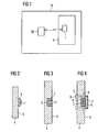
- FIG. 1 shows schematically a system comprising a document processing apparatus 16 with reader 22, in particular a banknote processing device, and a swap body 4 arranged therein with transponder 1.
- the Swap body 4 can be inserted into the document processing device 16 be filled, for example, with banknotes.
- the introduced Condition of the swap body 4 takes place between the reader 22 of the banknote processing device 16 and the transponder 1 of the interchangeable container 4 a wireless data and power transmission.
- the banknote processing device 16 may be constructed as described in WO 02/090217 of the Applicant, to the hereby express reference is made.
- this may be e.g. to the leadership a stack carrier unit instead of an open chain also a rack / Gear drive can be used, as it e.g. in the Swiss patent 445,761.
- the drive motor is preferred here with the stack carrier unit to be moved or be its part.
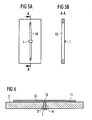
- FIG. 2 shows a first embodiment in which a transponder 1 directly on a container outer wall 2 of a not shown in detail Interchangeable container is mounted. Shown is only a section of the wall schematically in cross section. Between the transponder 1 and the outer wall 2 is a ferrite material 3 arranged to the transponder 1 to a Shield the swap body 4. This is the data and energy transfer from and / or to the transponder 1 exposed to less disturbing influences, and the transponder 1 can be better coupled into a magnetic field become.
- FIG. 3 shows a modification to the exemplary embodiment from FIG. 2.
- a recess 5 e.g. a hole or a cutout, provided in the form of the transponder 1.
- the transponder coil 1 is here in a ferrite shield 3 with a U-shaped cross section used in this recess 5.
- the use of ferrite shielding 3 is especially necessary when the swap body 4 of metallic Material is made. Otherwise, a magnetic would Field on the outside of the container 2 are so strongly attenuated that a Communication between a reader and the transponder 1 not it is possible.
- Figure 4 shows a development of the embodiment of Figure 3.
- Um To protect the transponder 1 mechanically, is above the recess 5 a Metal cover 7 mounted so that they the recess 5 completely covers.
- the metal cover 7 is from the container interior from with a suitable fastening device 8, for example a screw connection, attached. Between the outer surface 2 of the container wall and the metal cover 7 remains a dielectric gap 9, which is preferably filled with solid dielectric material.
- the transponder 1 is in such the recess 5 installed that the coil axis 6 of the transponder. 1 runs parallel to the surface of the container outer wall 2.
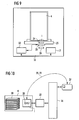
- FIGs 5a and 5b show an external view and in cross section another Embodiment in which a slot antenna 10 in the container outer wall 2 is formed, whereby the use of transponders in the frequency domain > 500 MHz (e.g., 868 MHz, 2.45 GHz).
- the transponder 1 with the two effective as an antenna connection In the middle of the long sides electrically contacted.
- the transponder 1 is located thereby on the protected inside of the container.
- the length of the Slot 10 is chosen to be at the desired working frequency forms an electrical resonance.
- FIG. 6 shows the structural design in another exemplary embodiment Structure of a planar antenna 11 on a container outer side 2.
- This is on the container outer side 2, a dielectric 12 and on this one the Planar antenna 11 forming metal layer applied.
- This structure can for example by a metal-coated Kunststoffofffie or by a metal-clad Epoxy resin (PCB) can be realized.
- PCB metal-clad Epoxy resin
- the metal layer 11 is preferably rectangular, with the side length the long sides of the rectangle is chosen so that they are in about half Wavelength of the desired working frequency corresponds. For example would be when using an RFID transponder in a typical RFID frequency of 2.45 GHz, the page length e.g. about 6 cm. there the side length of the two transverse sides can be smaller or larger than the half wavelength can be selected. Since the dimensions of the transverse sides of the strongly influence the electrical properties of such a planar antenna 11, However, when dimensioning the transverse sides are the electrical Requirements in the foreground.
- the Line 13 into a solid dielectric 15, e.g. a plastic material, embedded.
- the second connection of the transponder takes place directly on the container wall.
- the lead 13 may also be connected, for example, by a coaxial cable, e.g. in semi-rigid design, be executed, the transponder 1 then on attached anywhere on the inside of the container and with the antenna 11 can be connected.
- FIG. 7 shows schematically as a further embodiment, a transponder 1 in a swap body 4 with the possibility of sensors on the To address transponders that detect physical conditions in the container 4. For example, information such as “empty and refillable container” or “already filled and relocked” or “container open” or “filling limit almost reached. "For this purpose, the transponder 1 with provided at least one electrical connection, which at least as digital signal input can be used to view the container status information with suitable switching elements, e.g. Reed switch Microswitch, optical receiver (photodiode), etc. to capture. About one Reader 22, which is arranged in a document processing device The information collected can then be wireless from the transponder 1 of the container 4 are queried.
- suitable switching elements e.g. Reed switch Microswitch, optical receiver (photodiode), etc.
- the transponder can be 1 with at least one electrical connection as analog signal input be designed to use an A / D converter electrical voltages to be able to measure.
- analog sensors can then physical quantities such as pressure, temperature, path lengths, brightness, torsion the container housing, etc. at appropriate locations inside the container measured and by the transponder 1 via the reader 22 to the document processing device are sent, in which the container 4 was added is.
- the data transmission between reader 22 and transponder 1 can also be used for a clock control of the transponder or the associated Sensors / actuators are used.
- the transponder 1 comprises a non-volatile and very low-power data storage. This allows storage of characteristics and additional information with which the security and increase the tamper protection. It can, for example Serial numbers of individual banknotes including the stacking order and stored information about the quality of each banknote become.
- the currently recorded container statuses can be used together with occurring Events (opening, closing, removal, etc.) are saved, to rule out manipulation possibilities and a trouble-free continuation function to ensure power failure. This can be, for example a comparison of the currently recorded status with the last one stored container status / sensor data and a continuously updated Control status message of the higher-level document processing device respectively.
- Figure 8 shows an example of a closing mechanism of a swap body 4. Since closing mechanisms, which opened by external actuation are often a point of attack for swap bodies 4 is a Opening the swap body 4 only possible if the locking device is operated or released only by means which are within the Interchangeable container 4 are located.
- the exemplary embodiment illustrated in FIG. 8 includes one from within the container operated closing mechanism 18, 20 and one from the outside operated closing mechanism 21, wherein between the two closing mechanisms a frictional connection must be made. This traction becomes for a short period of time by means of one here realized by two pawls 20 Actuator made, which is controlled by the transponder 1 and the outer locking mechanism 21 locks or releases. At the actuator it is preferably an electromagnetic device, e.g. around an electromagnet. The actuator can additionally with an activatable or deactivatable color bomb be coupled.
- the method for opening the interchangeable container 4 in FIG. 8 is First with the passive transponder using an RFID reader To supply energy and thus the charge storage of the transponder charge. The next step is authentication between the Transponder and a reader done. After a successful authentication is provided to the actuator for a short period of time activate and thus a frictional connection between the inner 18, 20 and the outer 21 closing mechanism, so that the swap body 4 can be opened at this moment.
- the opening can be done by driving the actuator so as described in DE 103 48 569 A1, incorporated herein by reference becomes.
- the device for driving the preferably an energy storage for feeding the actuator, a Receiving unit for contactless receiving a control signal and a Control unit such as a transponder for controlling the power supply to the Actuator depending on the control signal, so that via the receiving unit Energy for charging the energy storage can be supplied.
- the the Receiving unit supplied energy can be converted into a voltage. It is advantageous if a first current path for a first partial flow for at least temporary control of the voltage to a default value is trained. This makes it possible, for example, the control unit to supply with this regulated voltage.
- a second current path for a second partial flow designed to charge the energy storage is a second current path for a second partial flow designed to charge the energy storage.
- the first rung and / or the second current path may be parallel to the control unit.
- a control circuit may be provided, which by a coordinated Influencing the first current path and the second current path the Voltage controls to the default value.
- the two Current paths each affected so that one through the second current path flowing second partial flow under the respective operating conditions maximum possible value.
- the first rung and / or the second current paths can each by means of a variable resistor, in particular of a transistor.
- a control signal contactless are transmitted to the control device and the actuator dependent from the control signal with an energy store of the control device be connected, so that the control device on contactless way Energy is supplied to recharge the energy storage.
- Electromagnets with permanent magnet support after the Principle of bistable relay operation to use.
- suitable pawls 20 folded or unfolded. In unfolded Position can lock by turning the externally accessible Closing mechanism 21 are opened, which, for example can be designed as a lock with key or lever device.
- Figure 9 shows an arrangement which helps to attack by a fend off false cassette.
- a way to deceive a document processing device in particular a banknote processing device, could namely consist in the connection cable between a Reader and the antenna of the reader with the purpose to extend, the antenna is within reading range of a first, fraudulently outside to bring the device positioned exchange container.
- a second, correctly inserted container treated, for example filled, without the reader with the transponder of this second Container communicates.
- the communication would be instead with the transponder of the first container outside the banknote processing device be handled. In this way, for example mark an empty container as filled and forward it in the system, where the actual whereabouts of the empty container in the transponder Amount of money would be incomprehensible.
- FIG. 9 shows a particularly advantageous attachment of the further transponder 24 into a plastic housing part 25, e.g. a floor plate, on which the swap body 4 is and on the back of the Readers antenna 23 is attached. Since an expansion only at the highest, possibly destructive disassembly of the housing part 25 is possible results in a especially high protection.
- the further transponder 24 can be used instead of between the container 4 and the reader antenna 23 also back the reader antenna 23 are attached as a transponder 26. Again, it is makes sense to attach the transponder 26 so that a removal of the same for Destruction leads or at least involves considerable difficulties is. It is also possible to provide both transponders 24 and 26.
- Figure 10 shows diagrammatically the authentication of a user by means of a smart card 27 opposite a swap body 4.
- a smart card 27 On the smart card 27 are stored use authorizations.
- the data record 28 the serial number of the transponder 1 of the swap body 4 included.
- the transmitted record 28 with a secret Key signed and then as a signed record 29 in the transponder 1 of the swap body 4 written back.
- the original one Record 28 also from the document processing apparatus shown in FIG 16 via the reader 22 in the memory of the transponder 1 of the interchangeable container 4, before being sent to the Chip card 27 is transmitted.
- This from the document processing device 16 transmitted original record 28 may, for example, the Number of documents 30 included by the document processing device 16 were transferred to the container 4.
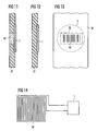
- FIG 11 is a development of an inside of the wall 31 of a Swap body 4 placed transponder 1 shown.
- a limited area 32 of the wall 31 is made of a transparent plastic.
- the Transponder 1 can display elements arranged behind the transparent area or drive an opto-sensor. This can be physical Conditions of the container and status information about the container contents for users directly on the swap body 4 visually readable become.
- FIG. 12 shows a variant in which at least the transparent region 32 or possibly the entire wall 31 only for the infrared wavelength range is transparent, or at least not for wavelengths in the visible spectral range. This is suitable e.g. to read one from the inside on the wall 31 applied IR barcodes or for communication by means of IR diodes, which are controlled by the transponder 1.
- FIG. 13 shows such an embodiment in plan view, in which in the swap body an IR-readable barcode 33 is mounted. Such a Barcode 33 can then be read out with conventional IR readers from the outside become.
- FIG. 14 shows a drill protection in the form of a long conductor loop 34, which is mounted on the inner surface of the container walls and the Container 4 should protect against drilling. Especially with swap bodies 4 made of plastic there is a risk of tampering by drilling Container 4, about to get to the closing mechanism. At least Particularly vulnerable portions of the container 4 are therefore with a Drill 34 provided.
- the illustrated conductor loop 34 is along the endangered points inside the container 4 and its continuous Conductivity by means of the already mentioned signal inputs of the transponder 1 checked. An interruption of the conductor loop 34 and thus a potentially successful attack on the container 4 can thus be easily detect by a query of the transponder 1.
- the drill protection can also be connected via the transponder 1 with a color bomb be.
- the conductor loop 34 already in the production of the container 4 in the container walls be poured. Through a meandering laying of the conductor loop 34 even large surfaces can be secured against drilling.
Abstract
Description
Claims (35)
- Wechselbehälter (4) zur Aufbewahrung von Wertdokumenten wie Banknoten, Schecks oder Ähnlichem, wobei der Behälter (4) vorgesehen ist, in ein Dokumentenverarbeitungsgerät (16) eingebracht zu werden, und wobei der Behälter (4) einen passiven Transponder (1) umfasst, um kontaktlos Informationssignale von dem Dokumentenverarbeitungsgerät (16) zu empfangen oder an dieses zu übermitteln und/oder um von dem Dokumentenverarbeitungsgerät (16) elektrische Energie kontaktlos zugeführt zu bekommen, dadurch gekennzeichnet, dass der Transponder (1) an eine Behälteraußenwand (2) oder in eine darin vorgesehene, außenliegende Aussparung (5) montiert ist.
- Wechselbehälter (4) nach Anspruch 1, dadurch gekennzeichnet, dass der Transponder (1) zum Behälter (4) hin mit Ferritmaterial (3) abgeschirmt ist.
- Wechselbehälter (4) nach Anspruch 2, dadurch gekennzeichnet, dass das Ferritmaterial (3) in Form eines Kerns mit U-förmigem Querschnitt in die Aussparung (5) montiert ist und eine Antennenspule umschließt.
- Wechselbehälter (4) nach Anspruch 1, dadurch gekennzeichnet, dass die Aussparung (5) mit einer Metallabdeckung (7) versehen ist und zwischen der Metallabdeckung (7) und der Außenwand (2) ein dielektrischer Spalt (9) vorgesehen ist.
- Wechselbehälter (4) nach Anspruch 4, dadurch gekennzeichnet, dass der dielektrische Spalt (9) als eine elektrisch isolierende Lackierung oder durch eine Kunststofffolie zwischen der Außenwand (2) und der Metallabdeckung (7) vorgesehen ist.
- Wechselbehälter (4) nach einem der Ansprüche 4 oder 5, dadurch gekennzeichnet, dass die Metallabdeckung (7) vom Inneren des Behälters (4) aus mittels einer Befestigungsvorrichtung (8) befestigt ist.
- Wechselbehälter (4) zur Aufbewahrung von Wertdokumenten wie Banknoten, Schecks oder Ähnlichem, wobei der Behälter (4) vorgesehen ist, in ein Dokumentenverarbeitungsgerät (16) eingebracht zu werden, und wobei der Behälter (4) einen passiven Transponder (1) umfasst, um kontaktlos Informationssignale von dem Dokumentenverarbeitungsgerät (16) zu empfangen oder an dieses zu übermitteln und/ oder um von dem Dokumentenverarbeitungsgerät (16) elektrische Energie kontaktlos zugeführt zu bekommen, dadurch gekennzeichnet, dass der Transponder (1) einen eine Antenne bildenden Schlitz (10) in einer Behälteraußenwand (2) und einen Antennenanschluss (13) umfasst, der die Mitten der Schlitzlängsseiten elektrisch kontaktiert.
- Wechselbehälter (4) nach Anspruch 6, dadurch gekennzeichnet, dass der Schlitz (10) mit einer dielektrischen Vergussmasse ausgefüllt ist.
- Wechselbehälter (4) zur Aufbewahrung von Wertdokumenten wie Banknoten, Schecks oder Ähnlichem, wobei der Behälter (4) vorgesehen ist, in ein Dokumentenverarbeitungsgerät (16) eingebracht zu werden, und wobei der Behälter (4) einen passiven Transponder (1) umfasst, um kontaktlos Informationssignale von dem Dokumentenverarbeitungsgerät (16) zu empfangen oder an dieses zu übermitteln und/oder um von dem Dokumentenverarbeitungsgerät (16) elektrische Energie kontaktlos zugeführt zu bekommen, dadurch gekennzeichnet, dass der Transponder (1) auf einer Behälteraußenwand (2) eine Planarantenne mit einer dielektrischen Schicht (12) und einer außen liegenden metallischen Schicht (11) sowie eine elektrisch leitende Verbindung (13) von der Planarantenne in das Behälterinnere umfasst.
- Wechselbehälter (4) nach Anspruch 9, dadurch gekennzeichnet, dass die dielektrische (12) und die außen liegende metallische (11) Schicht in Form einer metallbeschichteten Kunststoffolie (2) oder in Form einer metallkaschierten Epoxydharzplatte auf der Behälteraußenwand (2) aufgebracht sind.
- Wechselbehälter (4) zur Aufbewahrung von Wertdokumenten wie Banknoten, Schecks oder Ähnlichem, wobei der Behälter (4) vorgesehen ist, in ein Dokumentenverarbeitungsgerät (16) eingebracht zu werden, und wobei der Behälter (4) einen passiven Transponder (1) umfasst, um kontaktlos Informationssignale von dem Dokumentenverarbeitungsgerät (16) zu empfangen oder an dieses zu übermitteln und/oder um von dem Dokumentenverarbeitungsgerät (16) elektrische Energie kontaktlos zugeführt zu bekommen, dadurch gekennzeichnet, dass zumindest ein Bereich (32) einer Behälterwand über die gesamte Wanddicke aus einem nichtmetallischen Material, insbesondere aus Kunststoffmaterial, hergestellt ist und zumindest ein Teil des Transponders (1) auf der Behälterinnenseite des nichtmetallischen Materials montiert ist.
- Wechselbehälter (4) nach Anspruch 11, dadurch gekennzeichnet, dass der Transponder (1) in das Kunststoffmaterial eingegossen ist.
- Wechselbehälter (4) nach Anspruch 11, dadurch gekennzeichnet, dass der Transponder (1) in eine Aussparung (5) des nichtmetallischen Materials eingeklebt ist.
- Wechselbehälter (4) nach einem der Ansprüche 1 bis 13, dadurch gekennzeichnet, dass die Behälterwände überwiegend aus metallischem Werkstoff hergestellt sind.
- Wechselbehälter (4) nach einem der Ansprüche 11 bis 13, dadurch gekennzeichnet, dass die Behälterwände überwiegend oder vollständig aus Kunststoff hergestellt sind.
- Wechselbehälter (4) zur Aufbewahrung von Wertdokumenten wie Banknoten, Schecks oder Ähnlichem, wobei der Behälter (4)vorgesehen ist, in ein Dokumentenverarbeitungsgerät (16) eingebracht zu werden, und wobei der Behälter (4) einen passiven Transponder (1) umfasst, um kontaktlos Informationssignale von dem Dokumentenverarbeitungsgerät (16) zu empfangen oder an dieses zu übermitteln und/oder um von dem Dokumentenverarbeitungsgerät (16) elektrische Energie kontaktlos zugeführt zu bekommen, insbesondere nach einem der Ansprüche 1 bis 15, dadurch gekennzeichnet, dass der Transponder (1) mit mindestens einer Einrichtung im Inneren des Behälters zum Erfassen von physikalischen Zuständen des Behälters (4) gekoppelt ist.
- Wechselbehälter (4) zur Aufbewahrung von Wertdokumenten wie Banknoten, Schecks oder Ähnlichem, wobei der Behälter (4) vorgesehen ist, in ein Dokumentenverarbeitungsgerät (16) eingebracht zu werden, und wobei der Behälter (4) einen passiven Transponder (1) umfasst, um kontaktlos Informationssignale von dem Dokumentenverarbeitungsgerät (16) zu empfangen oder an dieses zu übermitteln und/oder um von dem Dokumentenverarbeitungsgerät (16) elektrische Energie kontaktlos zugeführt zu bekommen, insbesondere nach einem der Ansprüche 1 bis 16, dadurch gekennzeichnet, dass der Behälter (4) durch einen Kraftschluss zwischen einem äußeren (19) und einem inneren (18) Schließmechanismus geöffnet werden kann, wobei der Transponder (1) mit einem Aktuator im Inneren des Behälters gekoppelt ist, welcher einen solchen Kraftschluss herstellt.
- Wechselbehälter (4) nach Anspruch 17, dadurch gekennzeichnet, dass der durch den Aktuator hergestellte Kraftschluss ein elektrochemischer oder elektrophysikalischer ist.
- Wechselbehälter (4) nach Anspruch 17, dadurch gekennzeichnet, dass der innere Schließmechanismus (18) mindestens eine bistabile Sperrklinke (20) umfasst, welche durch impulsgesteuerte Elektromagnete mit Permanentmagnetunterstützung ein- oder ausgeklappt wird.
- Wechselbehälter (4) nach Anspruch 18 oder 19, dadurch gekennzeichnet, dass der Aktuator mit einer aktivierbaren oder deaktivierbaren Farbbombe gekoppelt ist.
- Wechselbehälter (4) nach einem der Ansprüche 17 bis 20, dadurch gekennzeichnet, dass der Transponder (1) mit einem Aktuator im Inneren des Behälters (4) gekoppelt ist, welcher zum Ansteuern von Anzeigeelementen oder einer Optosensorik vorgesehen ist.
- Wechselbehälter (4) nach einem der Ansprüche 17 bis 21, dadurch gekennzeichnet, dass eine Vorrichtung zum Ansteuern des Aktuators mit einem Energiespeicher zur Speisung des Aktuators, einer Empfangseinheit zum kontaktlosen Empfangen eines Steuersignals und einer Steuereinheit zur Steuerung der Energiezufuhr zum Aktuator abhängig vom Steuersignal versehen ist, wobei über die Empfangseinheit Energie zum Aufladen des Energiespeichers zuführbar ist.
- Wechselbehälter (4) nach einem der Ansprüche 1 bis 22, dadurch gekennzeichnet, dass zumindest ein Teil des Behälters (4) aus visuell transparentem Material (31) hergestellt ist.
- Wechselbehälter (4) nach einem der Ansprüche 1 bis 23, dadurch gekennzeichnet, dass zumindest ein Teil des Behälters (4) aus für IR-Strahlung durchlässigem Material (31) hergestellt ist.
- Wechselbehälter (4) nach einem der Ansprüche 1 bis 24, dadurch gekennzeichnet, dass der Behälter (4) mit einem Bohrschutz (34) zum Schutz gegen das Aufbohren des Behälters (4) versehen ist.
- Wechselbehälter (4) nach Anspruch 25, dadurch gekennzeichnet, dass der Bohrschutz (34) in Form einer langen Leiterschleife (34) ausgebildet ist.
- Wechselbehälter (4) nach Anspruch 25 oder 26, dadurch gekennzeichnet, dass der Bohrschutz (34) im Falle eines aus Kunststoff bestehenden Behälters (4) in die Behälterwände eingegossen ist.
- Wechselbehälter (4) nach einem der Ansprüche 1 bis 27, dadurch gekennzeichnet, dass der Transponder (1) mit einem nichtflüchtigen Datenspeicher verbunden ist.
- Wechselbehälter (4) nach einem der Ansprüche 1 bis 28, dadurch gekennzeichnet, dass der Transponder (1) ein RFID-Transponder ist.
- Dokumentenverarbeitungsgerät (16) zur Aufnahme eines Wechselbehälters (4) mit passivem Transponder (1), insbesondere nach einem der Ansprüche 1 bis 21, umfassend ein Lesegerät (22) zur Kommunikation mit dem passiven Transponder (1) des Wechselbehälters (4), dadurch gekennzeichnet, dass das Dokumentenverarbeitungsgerät (16) mindestens einen weiteren Transponder (24, 26) aufweist, wobei die Transponder bei in dem Dokumentenverarbeitungsgerät (16) aufgenommenem Wechselbehälter (4) derart zueinander angeordnet sind, dass das Lesegerät (22) abwechselnd mit dem passiven Transponder (1) des Wechselbehälters (4) und dem mindestens einen weiteren Transponder (24, 26) des Dokumentenverarbeitungsgeräts (16) kommunizieren kann.
- Dokumentenverarbeitungsgerät (16) nach Anspruch 30, dadurch gekennzeichnet, dass der mindestens eine weitere Transponder (24) in ein Gehäuseteil (25) des Dokumentenverarbeitungsgeräts (16) in von außen nicht zugänglicher Weise integriert ist.
- Verfahren zur Authentifizierung eines Benutzers mittels einer Chipkarte (27) gegenüber einem Wechselbehälter (4) zur Aufbewahrung von Wertdokumenten, wie Banknoten, Schecks oder Ähnlichem, welcher einen elektronischen Speicher enthält, gekennzeichnet durch die folgenden Schritte:Übertragen eines Datensatzes (28) aus dem Speicher des Wechselbehälters (4) an die Chipkarte (27),Signieren dieses Datensatzes (28) durch die Chipkarte (27) mittels einer zertifizierten Signatur, undZurückschreiben des signierten Datensatzes (29) in den Speicher des Wechselbehälters (4).
- Verfahren nach Anspruch 32, gekennzeichnet durch den weiteren Schritt des Schreibens des Datensatzes (28) von einem Dokumentenverarbeitungsgerät (16) in den Speicher des Wechselbehälters (4) vor dem Schritt des Übertragens des Datensatzes (28) an die Chipkarte (27).
- Verfahren nach Anspruch 32 oder 33, dadurch gekennzeichnet, dass der an die Chipkarte (27) übertragene Datensatz (28) die Seriennummer des Transponders (1) des Wechselbehälters (4) umfasst.
- System, umfassend:einen Wechselbehälter (4) zur Aufbewahrung von Wertdokumenten wie Banknoten, Schecks oder Ähnlichem, mit einem elektronischen Speicher,eine Chipkarte (27), geeignet zur Signierung von Daten,eine Kommunikationseinrichtung zum Übertragen von Daten zwischen dem Speicher des Wechselbehälters (4) und der Chipkarte (27), sowieeine Steuerungseinrichtung zur Durchführung des Verfahrens nach einem der Ansprüche 32 bis 34.
Applications Claiming Priority (2)
| Application Number | Priority Date | Filing Date | Title |
|---|---|---|---|
| DE10357695A DE10357695A1 (de) | 2003-12-10 | 2003-12-10 | Wechselbehälter zur Aufbewahrung von Wertdokumenten |
| DE10357695 | 2003-12-10 |
Publications (2)
| Publication Number | Publication Date |
|---|---|
| EP1541795A2 true EP1541795A2 (de) | 2005-06-15 |
| EP1541795A3 EP1541795A3 (de) | 2005-07-06 |
Family
ID=34485291
Family Applications (1)
| Application Number | Title | Priority Date | Filing Date |
|---|---|---|---|
| EP04026652A Withdrawn EP1541795A3 (de) | 2003-12-10 | 2004-11-10 | Wechselbehälter zur Aufbewahrung von Wertdokumenten |
Country Status (2)
| Country | Link |
|---|---|
| EP (1) | EP1541795A3 (de) |
| DE (1) | DE10357695A1 (de) |
Cited By (6)
| Publication number | Priority date | Publication date | Assignee | Title |
|---|---|---|---|---|
| WO2006128448A1 (de) * | 2005-06-01 | 2006-12-07 | Hardy Zissel | Anordnung mit transponder und metallischem element |
| DE102005056456A1 (de) * | 2005-11-26 | 2007-06-06 | Ingrid Dipl.-Ing. Schäffer | Vor-Ort Zustellung und Abholung von Waren in Pendelverpackungen |
| WO2007079332A2 (en) * | 2005-12-14 | 2007-07-12 | Checkpoint Systems, Inc. | Systems and methods for providing universal security for items |
| WO2008000424A1 (de) * | 2006-06-26 | 2008-01-03 | Giesecke & Devrient Gmbh | Verfahren zur montage eines transponders an einem gegenstand |
| DE102007039774A1 (de) * | 2007-08-21 | 2009-04-02 | Elsässer, Andreas | Vorrichtung zur Aufnahme von Datenträgern |
| EP2919202A1 (de) * | 2014-03-10 | 2015-09-16 | Assa Abloy Ab | RFID-angetriebene Verriegelungsvorrichtung |
Families Citing this family (7)
| Publication number | Priority date | Publication date | Assignee | Title |
|---|---|---|---|---|
| DE202005014867U1 (de) * | 2005-09-20 | 2006-03-02 | Gewande, Karl-Heinz | Antenne zur einmaligen und kontinuierlichen Erfassung von Tresorinhalten mittels RFID, Lesung der Daten im geöffneten und geschlossenen Zustand des Tresors |
| DE102009044784A1 (de) * | 2009-12-04 | 2011-06-09 | Wincor Nixdorf International Gmbh | Deposit-Einrichtung und Verfahren zur Annahme von Verwahrgut |
| DE102011123027B3 (de) | 2011-02-25 | 2019-09-12 | Minimax Gmbh & Co. Kg | Vorrichtung und Verfahren zur Kontrolle der Durchführung von Wartungsarbeiten an Brandlöschanlagen |
| DE102012217828A1 (de) | 2012-09-28 | 2014-04-03 | Harsco Infrastructure Services Gmbh | Transportierbare Vorrichtung mit Transponder |
| DE102014208286A1 (de) * | 2014-05-02 | 2015-11-05 | Prolim Gmbh | Behälter zur Aufbewahrung von Wertpapieren und Wertpapieraufbewahrungssystem |
| DE102017121290A1 (de) | 2017-09-14 | 2019-03-14 | Peri Gmbh | Vorrichtung zum Einsetzen eines Transponders |
| DE102019008128A1 (de) * | 2019-11-22 | 2021-05-27 | Giesecke+Devrient Currency Technology Gmbh | Verfahren zum Betreiben einer Sitzung eines Benutzers einer Banknotenbearbeitungsvorrichtung und Banknotenbearbeitungsvorrichtung |
Family Cites Families (15)
| Publication number | Priority date | Publication date | Assignee | Title |
|---|---|---|---|---|
| DE69125839T2 (de) * | 1991-12-30 | 1997-07-31 | Texas Instruments Inc | Eingebauter Chip-Transponder mit Antennenspule |
| SE501386C2 (sv) * | 1992-02-17 | 1995-01-30 | Securitas Ab | Förfarande för värdetransport |
| GB9220409D0 (en) * | 1992-09-28 | 1992-11-11 | Texas Instruments Holland | Shielded transponder |
| DE9409637U1 (de) * | 1994-06-15 | 1994-08-11 | Garny Sicherheitstechn Gmbh | Tresoranlage sowie Kassette hierfür |
| DE29519427U1 (de) * | 1995-12-08 | 1996-06-27 | Faust Holger | Anordnung zur Handhabung von Geldübergabetresoren |
| DE19639545C1 (de) * | 1996-09-26 | 1997-12-18 | Ikon Praezisionstechnik | Elektromagnetische Verriegelung für ein Zylinderschloß |
| DE19845584A1 (de) * | 1998-10-02 | 2000-04-06 | Garny Sicherheitstechn Gmbh | Schließfach mit elektromagnetischer Türverriegelung |
| WO2000021031A1 (en) * | 1998-10-06 | 2000-04-13 | Intermec Ip Corp. | Rfid tag having dipole over ground plane antenna |
| DE29907953U1 (de) * | 1999-05-04 | 1999-09-23 | Dette Banktechnik & Consulting | Mit einem Deckel verschließbarer Behälter zur Beförderung von Geld, Wertsachen, Belegen u.dgl. |
| EP1191869A2 (de) * | 1999-06-16 | 2002-04-03 | Reinhold Holtkamp | Netzwerkverbundener und zugangskodeverwendender annahmebehälter und verfahren zur annahme |
| GB2353067B (en) * | 1999-07-19 | 2001-07-18 | Spinnaker Int Ltd | Security cabinet,combined security unit and ATM pick unit,and ATM including such an arrangement |
| EP1228482B1 (de) * | 1999-10-20 | 2003-04-09 | IFCO Systems GmbH | Behälterfolgesystem und wiederverwendbarer behälter mit einem transponder |
| DE10119489C1 (de) * | 2001-04-20 | 2002-07-25 | Texas Instruments Deutschland | Batterieloser Transponder |
| US6618020B2 (en) * | 2001-12-18 | 2003-09-09 | Nokia Corporation | Monopole slot antenna |
| DE10204884A1 (de) * | 2002-02-06 | 2003-08-14 | Schreiner Gmbh & Co Kg | Transponderetikett |
-
2003
- 2003-12-10 DE DE10357695A patent/DE10357695A1/de not_active Withdrawn
-
2004
- 2004-11-10 EP EP04026652A patent/EP1541795A3/de not_active Withdrawn
Non-Patent Citations (1)
| Title |
|---|
| None |
Cited By (8)
| Publication number | Priority date | Publication date | Assignee | Title |
|---|---|---|---|---|
| WO2006128448A1 (de) * | 2005-06-01 | 2006-12-07 | Hardy Zissel | Anordnung mit transponder und metallischem element |
| US7889145B2 (en) | 2005-06-01 | 2011-02-15 | Hardy Zissel | Arrangement with a transponder and a metal element |
| DE102005056456A1 (de) * | 2005-11-26 | 2007-06-06 | Ingrid Dipl.-Ing. Schäffer | Vor-Ort Zustellung und Abholung von Waren in Pendelverpackungen |
| WO2007079332A2 (en) * | 2005-12-14 | 2007-07-12 | Checkpoint Systems, Inc. | Systems and methods for providing universal security for items |
| WO2007079332A3 (en) * | 2005-12-14 | 2007-09-20 | Checkpoint Systems Inc | Systems and methods for providing universal security for items |
| WO2008000424A1 (de) * | 2006-06-26 | 2008-01-03 | Giesecke & Devrient Gmbh | Verfahren zur montage eines transponders an einem gegenstand |
| DE102007039774A1 (de) * | 2007-08-21 | 2009-04-02 | Elsässer, Andreas | Vorrichtung zur Aufnahme von Datenträgern |
| EP2919202A1 (de) * | 2014-03-10 | 2015-09-16 | Assa Abloy Ab | RFID-angetriebene Verriegelungsvorrichtung |
Also Published As
| Publication number | Publication date |
|---|---|
| EP1541795A3 (de) | 2005-07-06 |
| DE10357695A1 (de) | 2005-07-07 |
Similar Documents
| Publication | Publication Date | Title |
|---|---|---|
| EP2415028B1 (de) | Mechatronische schliessvorrichtung | |
| DE10148830B4 (de) | Verfahren und System zur Authentifizierung eines ersten Sende-/Empfangsgeräts gegenüber einem zu diesem entfernt angeordneten zweiten Sende-/Empfangsgerät | |
| EP1541795A2 (de) | Wechselbehälter zur Aufbewahrung von Wertdokumenten | |
| EP2733681B1 (de) | Schließeinheit, Schließvorrichtung und Verfahren zum Entriegeln und/oder Verriegeln eines Schlosses | |
| WO2000007151A1 (de) | Sicherheitspapier sowie verfahren und vorrichtung zur prüfung der echtheit darauf aufgezeichneter urkunden | |
| WO2001077465A2 (de) | Elektrisch verriegelbare schwenkhebelbetätigung | |
| EP3479362B1 (de) | Schliessanordnung für einen schaltschrank und ein entsprechendes verfahren | |
| EP1463637B1 (de) | Wert- oder sicherheitsdokument mit einem schalter | |
| EP0730073A2 (de) | Schliessvorrichtung mit elektrischer Verriegelung | |
| DE60122202T2 (de) | Verfahren zum Eigentumstransfer durch Benutzung von Sicherheitsetitketten | |
| EP2565850B1 (de) | Mechatronische Schliessvorrichtung | |
| DE102005011042A1 (de) | Induktives Bauelement, insbesondere für einen elektronischen Schlüssel | |
| EP0877333A2 (de) | Vorrichtung zur drahtlosen Energieübertragung und Ausführung einer Aktion | |
| DE102010064257A1 (de) | Funkschlüssel mit Sicherheitselement und Antennenanordnung | |
| EP0815504A2 (de) | Spieljeton mit integriertem elektronischen datenträger | |
| EP3467245B1 (de) | Sicherheitskassette, gesamtvorrichtung mit einer sicherheitskassette und verfahren zum handhaben von wertscheinen | |
| EP0867015B1 (de) | Zusatzsicherheitsmerkmal für chipkarten | |
| DE19809574A1 (de) | Verfahren zur Sicherung der Nämlichkeit von Objekten sowie Vorrichtung zur Durchführung des Verfahrens | |
| DE102009005411A1 (de) | Geldautomat | |
| AT513287A1 (de) | Schlüssel und Zutrittskontrollvorrichtung mit Schlüssel | |
| EP2849158B1 (de) | e-Ticket mit Manipulationsschutz | |
| EP0542088A1 (de) | Schutzvorrichtung für Schaltungsteile und/oder Daten in einem elektrotechnischen Gerät | |
| DE102022125486A1 (de) | Rücknahmevorrichtung für Datenträger | |
| EP3279874B1 (de) | Zutrittskontrollvorrichtung | |
| EP1626376B1 (de) | Verkaufsautomat, insbesondere Parkscheinautomat |
Legal Events
| Date | Code | Title | Description |
|---|---|---|---|
| PUAI | Public reference made under article 153(3) epc to a published international application that has entered the european phase |
Free format text: ORIGINAL CODE: 0009012 |
|
| PUAL | Search report despatched |
Free format text: ORIGINAL CODE: 0009013 |
|
| AK | Designated contracting states |
Kind code of ref document: A2 Designated state(s): AT BE BG CH CY CZ DE DK EE ES FI FR GB GR HU IE IS IT LI LU MC NL PL PT RO SE SI SK TR |
|
| AX | Request for extension of the european patent |
Extension state: AL HR LT LV MK YU |
|
| AK | Designated contracting states |
Kind code of ref document: A3 Designated state(s): AT BE BG CH CY CZ DE DK EE ES FI FR GB GR HU IE IS IT LI LU MC NL PL PT RO SE SI SK TR |
|
| AX | Request for extension of the european patent |
Extension state: AL HR LT LV MK YU |
|
| 17P | Request for examination filed |
Effective date: 20060109 |
|
| AKX | Designation fees paid |
Designated state(s): AT BE BG CH CY CZ DE DK EE ES FI FR GB GR HU IE IS IT LI LU MC NL PL PT RO SE SI SK TR |
|
| 17Q | First examination report despatched |
Effective date: 20070326 |
|
| STAA | Information on the status of an ep patent application or granted ep patent |
Free format text: STATUS: THE APPLICATION IS DEEMED TO BE WITHDRAWN |
|
| 18D | Application deemed to be withdrawn |
Effective date: 20140603 |