EP1540152B1 - Systeme de traitement de gaz d'echappement comportant un systeme d'ionisation des gaz avec injection d'air ionise - Google Patents
Systeme de traitement de gaz d'echappement comportant un systeme d'ionisation des gaz avec injection d'air ionise Download PDFInfo
- Publication number
- EP1540152B1 EP1540152B1 EP03769543A EP03769543A EP1540152B1 EP 1540152 B1 EP1540152 B1 EP 1540152B1 EP 03769543 A EP03769543 A EP 03769543A EP 03769543 A EP03769543 A EP 03769543A EP 1540152 B1 EP1540152 B1 EP 1540152B1
- Authority
- EP
- European Patent Office
- Prior art keywords
- ionization
- burnt gas
- air injection
- exhaust
- ionized air
- Prior art date
- Legal status (The legal status is an assumption and is not a legal conclusion. Google has not performed a legal analysis and makes no representation as to the accuracy of the status listed.)
- Expired - Lifetime
Links
Images

Classifications
-
- B—PERFORMING OPERATIONS; TRANSPORTING
- B01—PHYSICAL OR CHEMICAL PROCESSES OR APPARATUS IN GENERAL
- B01D—SEPARATION
- B01D53/00—Separation of gases or vapours; Recovering vapours of volatile solvents from gases; Chemical or biological purification of waste gases, e.g. engine exhaust gases, smoke, fumes, flue gases, aerosols
- B01D53/32—Separation of gases or vapours; Recovering vapours of volatile solvents from gases; Chemical or biological purification of waste gases, e.g. engine exhaust gases, smoke, fumes, flue gases, aerosols by electrical effects other than those provided for in group B01D61/00
-
- F—MECHANICAL ENGINEERING; LIGHTING; HEATING; WEAPONS; BLASTING
- F01—MACHINES OR ENGINES IN GENERAL; ENGINE PLANTS IN GENERAL; STEAM ENGINES
- F01N—GAS-FLOW SILENCERS OR EXHAUST APPARATUS FOR MACHINES OR ENGINES IN GENERAL; GAS-FLOW SILENCERS OR EXHAUST APPARATUS FOR INTERNAL-COMBUSTION ENGINES
- F01N13/00—Exhaust or silencing apparatus characterised by constructional features
- F01N13/009—Exhaust or silencing apparatus characterised by constructional features having two or more separate purifying devices arranged in series
-
- F—MECHANICAL ENGINEERING; LIGHTING; HEATING; WEAPONS; BLASTING
- F01—MACHINES OR ENGINES IN GENERAL; ENGINE PLANTS IN GENERAL; STEAM ENGINES
- F01N—GAS-FLOW SILENCERS OR EXHAUST APPARATUS FOR MACHINES OR ENGINES IN GENERAL; GAS-FLOW SILENCERS OR EXHAUST APPARATUS FOR INTERNAL-COMBUSTION ENGINES
- F01N13/00—Exhaust or silencing apparatus characterised by constructional features
- F01N13/009—Exhaust or silencing apparatus characterised by constructional features having two or more separate purifying devices arranged in series
- F01N13/0097—Exhaust or silencing apparatus characterised by constructional features having two or more separate purifying devices arranged in series the purifying devices are arranged in a single housing
-
- F—MECHANICAL ENGINEERING; LIGHTING; HEATING; WEAPONS; BLASTING
- F01—MACHINES OR ENGINES IN GENERAL; ENGINE PLANTS IN GENERAL; STEAM ENGINES
- F01N—GAS-FLOW SILENCERS OR EXHAUST APPARATUS FOR MACHINES OR ENGINES IN GENERAL; GAS-FLOW SILENCERS OR EXHAUST APPARATUS FOR INTERNAL-COMBUSTION ENGINES
- F01N3/00—Exhaust or silencing apparatus having means for purifying, rendering innocuous, or otherwise treating exhaust
- F01N3/08—Exhaust or silencing apparatus having means for purifying, rendering innocuous, or otherwise treating exhaust for rendering innocuous
- F01N3/0892—Electric or magnetic treatment, e.g. dissociation of noxious components
-
- F—MECHANICAL ENGINEERING; LIGHTING; HEATING; WEAPONS; BLASTING
- F01—MACHINES OR ENGINES IN GENERAL; ENGINE PLANTS IN GENERAL; STEAM ENGINES
- F01N—GAS-FLOW SILENCERS OR EXHAUST APPARATUS FOR MACHINES OR ENGINES IN GENERAL; GAS-FLOW SILENCERS OR EXHAUST APPARATUS FOR INTERNAL-COMBUSTION ENGINES
- F01N3/00—Exhaust or silencing apparatus having means for purifying, rendering innocuous, or otherwise treating exhaust
- F01N3/08—Exhaust or silencing apparatus having means for purifying, rendering innocuous, or otherwise treating exhaust for rendering innocuous
- F01N3/10—Exhaust or silencing apparatus having means for purifying, rendering innocuous, or otherwise treating exhaust for rendering innocuous by thermal or catalytic conversion of noxious components of exhaust
- F01N3/18—Exhaust or silencing apparatus having means for purifying, rendering innocuous, or otherwise treating exhaust for rendering innocuous by thermal or catalytic conversion of noxious components of exhaust characterised by methods of operation; Control
- F01N3/20—Exhaust or silencing apparatus having means for purifying, rendering innocuous, or otherwise treating exhaust for rendering innocuous by thermal or catalytic conversion of noxious components of exhaust characterised by methods of operation; Control specially adapted for catalytic conversion
-
- F—MECHANICAL ENGINEERING; LIGHTING; HEATING; WEAPONS; BLASTING
- F01—MACHINES OR ENGINES IN GENERAL; ENGINE PLANTS IN GENERAL; STEAM ENGINES
- F01N—GAS-FLOW SILENCERS OR EXHAUST APPARATUS FOR MACHINES OR ENGINES IN GENERAL; GAS-FLOW SILENCERS OR EXHAUST APPARATUS FOR INTERNAL-COMBUSTION ENGINES
- F01N3/00—Exhaust or silencing apparatus having means for purifying, rendering innocuous, or otherwise treating exhaust
- F01N3/08—Exhaust or silencing apparatus having means for purifying, rendering innocuous, or otherwise treating exhaust for rendering innocuous
- F01N3/10—Exhaust or silencing apparatus having means for purifying, rendering innocuous, or otherwise treating exhaust for rendering innocuous by thermal or catalytic conversion of noxious components of exhaust
- F01N3/24—Exhaust or silencing apparatus having means for purifying, rendering innocuous, or otherwise treating exhaust for rendering innocuous by thermal or catalytic conversion of noxious components of exhaust characterised by constructional aspects of converting apparatus
- F01N3/30—Arrangements for supply of additional air
-
- F—MECHANICAL ENGINEERING; LIGHTING; HEATING; WEAPONS; BLASTING
- F01—MACHINES OR ENGINES IN GENERAL; ENGINE PLANTS IN GENERAL; STEAM ENGINES
- F01N—GAS-FLOW SILENCERS OR EXHAUST APPARATUS FOR MACHINES OR ENGINES IN GENERAL; GAS-FLOW SILENCERS OR EXHAUST APPARATUS FOR INTERNAL-COMBUSTION ENGINES
- F01N2240/00—Combination or association of two or more different exhaust treating devices, or of at least one such device with an auxiliary device, not covered by indexing codes F01N2230/00 or F01N2250/00, one of the devices being
- F01N2240/38—Combination or association of two or more different exhaust treating devices, or of at least one such device with an auxiliary device, not covered by indexing codes F01N2230/00 or F01N2250/00, one of the devices being an ozone (O3) generator, e.g. for adding ozone after generation of ozone from air
-
- Y—GENERAL TAGGING OF NEW TECHNOLOGICAL DEVELOPMENTS; GENERAL TAGGING OF CROSS-SECTIONAL TECHNOLOGIES SPANNING OVER SEVERAL SECTIONS OF THE IPC; TECHNICAL SUBJECTS COVERED BY FORMER USPC CROSS-REFERENCE ART COLLECTIONS [XRACs] AND DIGESTS
- Y02—TECHNOLOGIES OR APPLICATIONS FOR MITIGATION OR ADAPTATION AGAINST CLIMATE CHANGE
- Y02A—TECHNOLOGIES FOR ADAPTATION TO CLIMATE CHANGE
- Y02A50/00—TECHNOLOGIES FOR ADAPTATION TO CLIMATE CHANGE in human health protection, e.g. against extreme weather
- Y02A50/20—Air quality improvement or preservation, e.g. vehicle emission control or emission reduction by using catalytic converters
-
- Y—GENERAL TAGGING OF NEW TECHNOLOGICAL DEVELOPMENTS; GENERAL TAGGING OF CROSS-SECTIONAL TECHNOLOGIES SPANNING OVER SEVERAL SECTIONS OF THE IPC; TECHNICAL SUBJECTS COVERED BY FORMER USPC CROSS-REFERENCE ART COLLECTIONS [XRACs] AND DIGESTS
- Y02—TECHNOLOGIES OR APPLICATIONS FOR MITIGATION OR ADAPTATION AGAINST CLIMATE CHANGE
- Y02T—CLIMATE CHANGE MITIGATION TECHNOLOGIES RELATED TO TRANSPORTATION
- Y02T10/00—Road transport of goods or passengers
- Y02T10/10—Internal combustion engine [ICE] based vehicles
- Y02T10/12—Improving ICE efficiencies
Definitions
- the invention proposes a system for treating the exhaust gases of a motor vehicle combustion engine, in particular a diesel engine or a lean gasoline engine, comprising a burnt gas exhaust circuit, of the type in which the exhaust circuit comprises a flue gas ionization system.
- HC unburned hydrocarbons CO carbon monoxide
- NOx nitrogen oxides particulates
- This oxidation reaction is all the more effective as the temperature of the catalyst is high. Therefore, it is sought to have this catalyst as close as possible to the outlet of the combustion chamber of each cylinder of the engine.
- NOx-trap The treatment of nitrogen oxides NOx can be envisaged by means of a NOx nitrogen oxide trap called "NOx-trap".
- the use of the nitrogen oxide trap is conditioned by the possibility of occasionally increasing the richness of the exhaust gases that pass through the trap.
- the technique consists in forming metastable species, free radicals and very reactive ions, by collision between the molecules of the gas and the energetic electrons produced by a discharge, and this, without raising the temperature of the medium.
- This discharge is obtained by applying, between two electrodes whose geometric configurations may be diverse, high voltage and high frequency signals.
- discharges modify the composition of the gaseous mixture by favoring reactions such as the oxidation of nitric oxide NO to nitrogen dioxide NO 2 , the formation of hydrocarbons. partially oxidized from the unburnt, and finally oxidation reactions of the particles leading to their activation.
- these plasma-generating discharges which are located upstream of the catalyst or in the catalyst make it possible to obtain reduction rates higher than those achieved with a catalyst alone. , and this in a much wider temperature range.
- plasma-generating discharges facilitate the soot combustion reaction necessary for the regeneration of the filter media.
- oxidizing activated species such as ozone O 3 and nitrogen dioxide NO 2
- reducing species such as partially oxidized hydrocarbons and activated soot
- ozonizer When non-thermal plasmas are used as "ozonizer" via the ambient air treatment, it is possible to produce up to 50g of ozone O 3 per kWh consumed. In this case, the atomic oxygen O formed in the ambient air is entirely available for the formation of ozone O 3 .
- the competing reactions to the production of ozone O 3, such as NO nitric oxide production reactions, are significant only when the powers used are sufficient to introduce a rise in temperature which favors the kinetics of formation of carbon monoxide. nitrogen NO.
- the parameters limiting the production of ozone are the temperature (ozone O 3 being thermodynamically unstable from 600-650 K) and the water vapor content (degree of hygrometry).
- the invention aims to improve the treatment of nitrogen oxides by non-thermal plasmas as described in WO03 / 027452A, which is considered as the state of the art according to Article 54 (3) EPC.
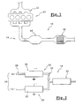
- FIG. 1 shows an internal combustion engine 10 which is produced in accordance with the teachings of the invention.
- the engine 10 is here of the diesel type or lean type gasoline type, that is to say that it operates with an excess of oxygen with respect to stoichiometric conditions.
- the engine 10 comprises an intake gas intake circuit 12 and a flue gas exhaust circuit 14 G.
- the exhaust circuit 14 comprises a depollution device 16, which processes the flue gases G so as to limit the discharge of pollutants into the atmosphere.
- the pollution control device 16 comprises a flue gas treatment system 18 which makes it possible to convert nitrogen monoxide NO to nitrogen dioxide NO 2 . Downstream of the treatment system 18, the depollution device 16 comprises a catalyst 20 which processes nitrogen dioxide NO 2 to transform it into nitrogen N 2 and oxygen O 2 which are natural constituents of air.
- the treatment system 18 comprises a flue gas ionization system 22 which consists of a reactor 32 of the non-thermal plasma generating discharge type.
- This reactor makes it possible to oxidize nitric oxide NO to nitrogen dioxide NO 2 .
- the oxidation of nitrogen monoxide NO to NO 2 is carried out directly or indirectly via atomic oxygen.
- nitrogen dioxide NO 2 reaches concentrations such as the reduction reaction NO 2 + O ⁇ NO + O 2 neutralizes the initial oxidation reaction.
- the treatment system 18 comprises an ionized air injection system 24 which is here arranged downstream of the ionization system 22 of the flue gas G, however, according to a variant (not shown) of the invention, the ionized air injection system 24 is arranged upstream of the ionization system 22 of the flue gases G.
- This ionized air injection system 24 comprises an air ionization system 26 which consists of a non-thermal plasma generating discharge type reactor.
- the plasmas produced in these reactors 22, 26, 32 are so-called non-thermal plasmas, generated by discharges of the "corona discharge" type. They are produced between bare electrodes or covered with dielectric barriers of various configurations ranging from parallel planes, and in this case with at least one dielectric barrier, to highly heterogeneous applied field geometries (multipoints-planes, wire or screw-plane). coplanar, coaxial wire or screw-cylinder, etc ).
- inter-electrode distances (defined as the distances between electrodes in the absence of dielectric, between the electrode and the dielectric in the presence of a single dielectric barrier, between dielectrics in the presence of two dielectric barriers), may be identical or different for each reactors and otherwise variable depending on the treatment conditions (gas flow to be treated for example).
- the gaseous effluents can flow perpendicularly or parallel to the plasma.
- the feed of the reactors 22, 26, 32 which may be common or differentiated for each reactor 22, 26, 32, provides a variable voltage that may be continuous, pulsed or alternating.
- the ionized air injection system 24 comprises an ambient air intake circuit 28 which connects the reactor 26 to the ambient air via an air filter (not shown).
- the reactor 26 converts the oxygen O contained in the air into ozone O 3 , and is capable of producing approximately 50 g of ozone O 3 per kWh consumed.
- the ionized air which comprises the ozone O 3 produced is then injected into the exhaust circuit 14 via an injection pipe 30 downstream of the ionization system 22 of the flue gases G so that the ozone O 3 produced reacts with the nitrogen monoxide NO initially contained in the flue gas G, when the ionized air injection system 24 is arranged upstream of the flue gas ionization system G, or with the NO residual nitric oxide contained in the flue gas G when the ionized air injection system 24 is arranged downstream of the flue gas ionization system 22 G.
- the treatment system 18 also includes unrepresented means for controlling the air ionization reactor 26 to produce the amount of ozone O 3 needed for the conversion of all the nitric oxide NO.
- the gas ionization system 32 comprises a plurality of reactors 32, here three in number, which are arranged in series and which successively ionize the flue gases G.
- the amount of nitric oxide NO converted to nitrogen dioxide NO 2 is close to the asymptotic limit value defined above, so that the ionized air injection system must produce only a reduced amount of O 3 ozone.
- the various reactors 32 are compartments of a single enclosure which are separated from each other by walls 34, which may be sealed or not.
- the two reactors that of the system the ionization of the gases 22 and that of the air ionization system 26 are two compartments of a single enclosure which are separated from each other by a wall 34 which is sealed.
- the gas ionization system 22 may comprise only one reactor 32, as shown in FIGS. 2 and 4, or it may comprise several reactors 32 arranged in series which are themselves compartments of a single enclosure.
- the various reactors 26, 32 are electrically powered by a single supply or by high voltage supplies which may be identical or differentiated according to the function of the reactor 26, 32 to which they are connected. are associated.
Landscapes
- Engineering & Computer Science (AREA)
- Chemical & Material Sciences (AREA)
- Chemical Kinetics & Catalysis (AREA)
- General Engineering & Computer Science (AREA)
- Mechanical Engineering (AREA)
- Combustion & Propulsion (AREA)
- Health & Medical Sciences (AREA)
- Toxicology (AREA)
- Oil, Petroleum & Natural Gas (AREA)
- General Chemical & Material Sciences (AREA)
- Analytical Chemistry (AREA)
- Exhaust Gas After Treatment (AREA)
- Treating Waste Gases (AREA)
- Physical Or Chemical Processes And Apparatus (AREA)
Description
- L'invention propose un système de traitement des gaz d'échappement d'un moteur à combustion de véhicule automobile, notamment d'un moteur diesel ou d'un moteur à essence à mélange pauvre, comportant un circuit d'échappement de gaz brûlés, du type dans lequel le circuit d'échappement comporte un système d'ionisation des gaz brûlés.
- La réglementation concernant les émissions de véhicules concerne essentiellement quatre types de polluants : les hydrocarbures imbrûlés HC, le monoxyde de carbone CO, les oxydes d'azote NOx et les particules.
- Dans le cas d'un moteur fonctionnant avec un excès d'oxygène, c'est-à-dire un moteur du type à essence à mélange pauvre ou du type diesel, la réduction des émissions d'hydrocarbures imbrûlés HC et de monoxyde de carbone CO est obtenue grâce à un catalyseur d'oxydation qui, dans de grandes proportions, les transforme en dioxyde de carbone CO2.
- Cette réaction d'oxydation est d'autant plus efficace que la température du catalyseur est élevée. C'est pourquoi, on cherche à disposer ce catalyseur le plus près possible de la sortie de la chambre de combustion de chaque cylindre du moteur.
- Le traitement des oxydes d'azote NOx peut être envisagé au moyen d'un piège à oxydes d'azote NOx dit "NOx-trap".
- Dans le cas d'un moteur à mélange pauvre, l'utilisation du piège à oxydes d'azote est conditionnée par la possibilité d'augmenter ponctuellement la richesse des gaz d'échappement qui traversent le piège.
- Toutefois, aujourd'hui, ces systèmes de traitement des oxydes d'azote NOx et des d'hydrocarbures imbrûlés HC sont encore très peu utilisés car leur efficacité n'est pas optimale dans toutes les conditions de roulage. Par ailleurs, leur coût n'est pas négligeable et leur utilisation entraîne des surconsommations importantes de carburant.
- Pour pallier leur manque d'efficacité, des travaux sur le couplage de ces systèmes avec la technologie des plasmas non-thermiques sont en cours.
- La technique consiste à former des espèces métastables, des radicaux libres et des ions très réactifs, par collision entre les molécules du gaz et les électrons énergétiques produits par une décharge, et ceci, sans élévation de la température du milieu.
- Cette décharge est obtenue en appliquant, entre deux électrodes dont les configurations géométriques peuvent être diverses, des signaux de tension et fréquence élevées. Dans les gaz d'échappement des moteurs dits à mélange pauvre, de telles décharges modifient la composition du mélange gazeux en favorisant des réactions telles que l'oxydation de monoxyde d'azote NO en dioxyde d'azote NO2, la formation d'hydrocarbures partiellement oxydés à partir des imbrûlés, et enfin des réactions d'oxydation des particules conduisant à leur activation.
- Combinées à un système de post-traitement catalytique de réduction des oxydes d'azote NOx, ces décharges génératrices de plasma qui sont localisées en amont du catalyseur ou dans le catalyseur permettent d'obtenir des taux de réduction supérieurs à ceux atteints avec un catalyseur seul, et ceci dans un domaine de température beaucoup plus large.
- Combinées à un filtre à particules, les décharges génératrices de plasma facilitent la réaction de combustion de la suie, nécessaire à la régénération du média filtrant. En effet, la formation d'espèces activées oxydantes, telles que l'ozone O3 et le dioxyde d'azote NO2, et d'espèces réductrices, telles que des hydrocarbures partiellement oxydés et de la suie activée, est favorable à un démarrage de l'oxydation des particules à plus basse température.
- Afin d'assurer des efficacités de réduction toujours plus performantes, il est nécessaire d'obtenir, dans un premier temps, une conversion optimale du monoxyde d'azote NO en dioxyde d'azote NO2.
- De manière générale, deux réactions principales mènent à l'oxydation du monoxyde d'azote NO en dioxyde d'azote NO2 :
NO+O+M → NO 2 +M ,
avec M = N2 ou O2, et
NO + O 3 → NO 2 + O 2
- Lorsque les plasmas non-thermiques sont utilisés en tant que "ozoneur" via le traitement de l'air ambiant, il est possible de produire jusqu'à 50g d'ozone O3 par kWh consommé. Dans ce cas, l'oxygène atomique O formé dans l'air ambiant est entièrement disponible pour la formation d'ozone O3.
- Les réactions concurrentes à la production d'ozone O3 telles que les réactions de production de monoxyde d'azote NO, n'interviennent significativement que lorsque les puissances utilisées sont suffisantes pour introduire une élévation de température qui favorise la cinétique de formation de monoxyde d'azote NO. Les paramètres limitant la production d'ozone sont la température (l'ozone O3 étant thermodynamiquement instable à partir de 600-650 K) et la teneur en vapeur d'eau (degré d'hygrométrie).
- Dans les publications "NO Oxidation Process in Dielectric Barrier Discharge using Multipoint-to-plane Electrodes" et "NOx removal for diesel Engine exhaust by ozone injection method" présentées lors du congrès "Non thermal plasma techonlogy for pollution control" en avril 2001 en Corée du Sud, il a été proposé d'injecter de l'air ionisé par un plasma non thermique, c'est à dire de l'air qui comporte une forte concentration en ozone O3 dans les gaz d'échappement. Voir aussi les documents FR2481945A et GB2284771A.
- Bien que de tels procédés permettent de réduire notablement la quantité d'oxydes d'azote NOx présents dans les gaz d'échappement, leur efficacité est limitée à environ 60%.
- L'invention vise à améliorer le traitement des oxydes d'azote par les plasmas non thermiques tels que décrits dans le document WO03/027452A, qui est considéré comme l'état de la technique selon l'article 54(3) CBE.
- L'invention propose donc un système de traitement du type décrit précédemment, dans lequel un circuit d'échappement comporte: un système d'injection d'air ionisé en amont et/ou en aval du système d'ionisation des gaz brûlés ;
- des moyens d'ionisation de l'air ambiant qui transforment une partie de l'oxygène contenu dans l'air ambiant en ozone ;
- les moyens d'ionisation de l'air et le système d'ionisation des gaz brûlés consistent chacun en au moins un réacteur du type à décharges génératrices de plasma non thermiques ;
- le système d'ionisation des gaz brûlés comporte plusieurs réacteurs agencés en série qui ionisent successivement les gaz brûlés.
- Selon d'autres caractéristiques de l'invention :
- les différents réacteurs sont des compartiments séparés d'une enceinte unique ;
- le circuit d'échappement comporte un catalyseur de traitement des oxydes d'azote qui est situé en aval du système d'injection d'air ionisé.
- D'autres caractéristiques et avantages de l'invention apparaîtront à la lecture de la description détaillée qui suit pour la compréhension de laquelle on se reportera aux figures annexées parmi lesquelles :
- la figure 1 est une représentation schématique d'une ligne d'échappement d'un moteur à combustion qui comporte un système de traitement conforme à l'invention ;
- la figure 2 est une représentation schématique du système de traitement représenté à la figure 1 ;
- les figures 3 à 5 sont des vues similaires à celle de la figure 2 représentant des variantes de réalisation de l'invention.
- Dans la description qui va suivre, des éléments identiques, similaires ou analogues seront désignés par les mêmes chiffres de référence.
- On a représenté à la figure 1 un moteur à combustion interne 10 qui est réalisé conformément aux enseignements de l'invention.
- Le moteur 10 est ici du type diesel ou du type à essence à mélange pauvre, c'est à dire qu'il fonctionne avec un excès d'oxygène par rapport aux conditions stoechiométriques.
- Le moteur 10 comporte un circuit d'admission 12 de gaz d'admission et un circuit d'échappement 14 de gaz brûlés G.
- Le circuit d'échappement 14 comporte un dispositif de dépollution 16, qui traite les gaz brûlés G de manière à limiter le rejet de polluants dans l'atmosphère.
- Le dispositif de dépollution 16 comporte un système de traitement 18 des gaz brûlés G qui permet de transformer le monoxyde d'azote NO en dioxyde d'azote NO2. En aval du système de traitement 18, le dispositif de dépollution 16 comporte un catalyseur 20 qui traite le dioxyde d'azote NO2 pour le transformer en azote N2 et en oxygène O2 qui sont des constituants naturels de l'air.
- Comme on l'a représenté à la figure 2, le système de traitement 18 comporte un système d'ionisation 22 des gaz brûlés G qui consiste en un réacteur 32 du type à décharges génératrices de plasma non thermique.
- Ce réacteur permet d'oxyder le monoxyde d'azote NO en dioxyde d'azote NO2. L'oxydation du monoxyde d'azote NO en dioxyde d'azote NO2 s'effectue directement ou indirectement via l'oxygène atomique. Or, il s'avère, et l'ensemble des études menées sur le sujet le confirme, que cette conversion du monoxyde d'azote NO en dioxyde d'azote NO2 ne peut être complète et tend en fait vers une limite asymptotique, en particulier du fait que le dioxyde d'azote NO2 atteint des concentrations telles que la réaction de réduction
NO 2 + O → NO + O 2
neutralise la réaction d'oxydation initiale.
A cet effet, et conformément à l'invention, le système de traitement 18 comporte un système d'injection d'air ionisé 24 qui est ici agencé en aval du système d'ionisation 22 des gaz brûlés G, cependant, selon une variante (non représentée) de l'invention, le système d'injection d'air ionisé 24 est agencé en amont du système d'ionisation 22 des gaz brûlés G. - Ce système d'injection d'air ionisé 24 comporte un système d'ionisation de l'air 26 qui consiste en un réacteur du type à décharges génératrices de plasma non thermique.
- Les plasmas produits dans ces réacteurs 22, 26, 32 sont des plasmas dits non thermiques, générés par des décharges de type "décharge couronne". Ils sont produits entre des électrodes nues ou recouvertes de barrières diélectriques de configurations variées pouvant aller de plans parallèles, et dans ce cas avec au moins une barrière diélectrique, à des géométries à champ appliqué fortement hétérogène (multipointes-plans, fil ou vis-plan coplanaires, fil ou vis-cylindre coaxiaux, etc... ).
- Les distances inter-électrodes (définies comme les distances entre électrodes en absence de diélectrique, entre l'électrode et le diélectrique en présence d'une unique barrière diélectrique, entre diélectriques en présence de deux barrières diélectriques), peuvent être identiques ou différentes pour chacun des réacteurs et par ailleurs variables suivant les conditions de traitement (débit de gaz à traiter par exemple).
- Les effluents gazeux, injectés à pression atmosphérique ou différente, peuvent s'écouler perpendiculairement ou parallèlement au plasma. Enfin, suivant la géométrie adoptée, l'alimentation des réacteurs 22, 26, 32, qui peut être commune ou différenciée pour chaque réacteur 22, 26, 32, fournit une tension variable qui pourra être continue, pulsée ou alternative.
- Le système d'injection d'air ionisé 24 comporte un circuit d'admission d'air ambiant 28 qui relie le réacteur 26 à l'air ambiant par l'intermédiaire d'un filtre à air (non représenté).
- Conformément à l'invention, le réacteur 26 transforme l'oxygène O contenu dans l'air en ozone O3, et il est apte à produire environ 50g d'ozone O3 par kWh consommé.
- L'air ionisé qui comporte l'ozone O3 produit est alors injecté dans le circuit d'échappement 14 par l'intermédiaire d'un conduit d'injection 30 en aval du système d'ionisation 22 des gaz brûlés G de sorte que l'ozone O3 produit réagisse avec le monoxyde d'azote NO initialement contenu dans les gaz brûlés G, lorsque le système d'injection d'air ionisé 24 est agencé en amont du système d'ionisation des gaz brûlés G, ou bien avec le monoxyde d'azote NO résiduel contenu dans les gaz brûlés G lorsque le système d'injection d'air ionisé 24 est agencé en aval du système d'ionisation 22 des gaz brûlés G.
- Le système de traitement 18 comporte aussi des moyens non représentés de contrôle du réacteur 26 d'ionisation de l'air pour produire la quantité d'ozone O3 nécessaire pour la conversion de la totalité du monoxyde d'azote NO.
- Il est ainsi possible de convertir la totalité du monoxyde d'azote NO contenu dans les gaz brûlés G.
- Selon une première variante de l'invention représentée à la figure 3, le système d'ionisation des gaz 32 comporte plusieurs réacteurs 32, ici au nombre de trois, qui sont agencés en série et qui ionisent successivement les gaz brûlés G.
- Puisque les gaz brûlés G sont ionisés plusieurs fois, la quantité de monoxyde d'azote NO converti en dioxyde d'azote NO2 est proche de la valeur limite asymptotique définie ci-dessus, de sorte que le système d'injection d'air ionisé ne doit produire qu'une quantité réduite d'ozone O3.
- Selon un mode de réalisation préféré de l'invention représenté aux figures 3 et 5, les différents réacteurs 32 sont des compartiments d'une enceinte unique qui sont séparés les uns des autres par des parois 34, qui peuvent être étanches ou non.
- Selon une deuxième variante de l'invention représentée aux figures 4 et 5, les deux réacteurs, celui du système d'ionisation des gaz 22 et celui du système d'ionisation d'air 26, sont deux compartiments d'une enceinte unique qui sont séparés l'un de l'autre par une paroi 34 qui est étanche.
- Selon cette variante, le système d'ionisation des gaz 22 peut ne comporter qu'un seul réacteur 32, comme représenté aux figure 2 et 4, ou bien il peut comporter plusieurs réacteurs 32 agencés en série qui sont eux-mêmes des compartiments d'une enceinte unique.
- Un tel agencement permet de réduire le volume total du dispositif de traitement 18 qui consiste alors en une enceinte unique.
- Quelle que soit la variante de réalisation du dispositif de traitement 18, les différents réacteurs 26, 32 sont alimentés électriquement par une alimentation unique ou bien par des alimentations hautes tensions qui peuvent être identiques ou bien différenciées selon la fonction du réacteur 26, 32 auquel elles sont associées.
Claims (3)
- Système de traitement (16) des gaz d'échappement (G) d'un moteur à combustion (10) de véhicule automobile, notamment d'un moteur diesel ou d'un moteur à essence à mélange pauvre, comportant un circuit d'échappement (14) de gaz brûlés (G), du type dans lequel le circuit d'échappement (14) comporte un système d'ionisation (22) des gaz brûlés (G) et un système d'injection d'air ionisé (24) en amont et/ou en aval du système d'ionisation (22) des gaz brûlés (G), qui comporte des moyens d'ionisation (26) de l'air ambiant qui transforment une partie de l'oxygène contenu dans l'air ambiant en ozone, et du type dans lequel les moyens d'ionisation (26) de l'air et le système d'ionisation (22) des gaz brûlés (G) consistent chacun en au moins un réacteur (26, 32) du type à décharges génératrices de plasma non thermique,
le système d'ionisation (22) des gaz brûlés (G) comportant plusieurs réacteurs (32) agencés en série qui ionisent successivement les gaz brûlés (G). - Système de traitement (16) selon la revendication précédente, caractérisé en ce que les différents réacteurs sont des compartiments séparés d'une enceinte unique (18).
- Système de traitement (16) selon l'une quelconque des revendications précédentes, caractérisé en ce que le circuit d'échappement (14) comporte un catalyseur (20) de traitement des oxydes d'azote qui est situé en aval du système d'injection d'air ionisé (24).
Applications Claiming Priority (3)
| Application Number | Priority Date | Filing Date | Title |
|---|---|---|---|
| FR0210752A FR2844000B1 (fr) | 2002-08-30 | 2002-08-30 | Systeme de traitement de gaz d'echappement comportant un systeme d'ionisation des gaz avec injection d'air ionise |
| FR0210752 | 2002-08-30 | ||
| PCT/FR2003/002614 WO2004020798A1 (fr) | 2002-08-30 | 2003-08-29 | Systeme de traitement de gaz d'echappement comportant un systeme d'ionisation des gaz avec injection d'air ionise |
Publications (2)
| Publication Number | Publication Date |
|---|---|
| EP1540152A1 EP1540152A1 (fr) | 2005-06-15 |
| EP1540152B1 true EP1540152B1 (fr) | 2006-04-12 |
Family
ID=31503001
Family Applications (1)
| Application Number | Title | Priority Date | Filing Date |
|---|---|---|---|
| EP03769543A Expired - Lifetime EP1540152B1 (fr) | 2002-08-30 | 2003-08-29 | Systeme de traitement de gaz d'echappement comportant un systeme d'ionisation des gaz avec injection d'air ionise |
Country Status (8)
| Country | Link |
|---|---|
| US (1) | US7121079B2 (fr) |
| EP (1) | EP1540152B1 (fr) |
| JP (1) | JP2005537419A (fr) |
| AT (1) | ATE323221T1 (fr) |
| DE (1) | DE60304585T2 (fr) |
| ES (1) | ES2263034T3 (fr) |
| FR (1) | FR2844000B1 (fr) |
| WO (1) | WO2004020798A1 (fr) |
Families Citing this family (17)
| Publication number | Priority date | Publication date | Assignee | Title |
|---|---|---|---|---|
| US7089922B2 (en) * | 2004-12-23 | 2006-08-15 | Cummins, Incorporated | Apparatus, system, and method for minimizing NOx in exhaust gasses |
| JP2006307802A (ja) * | 2005-05-02 | 2006-11-09 | Toyota Central Res & Dev Lab Inc | 排ガス浄化装置 |
| JP4263711B2 (ja) * | 2005-09-16 | 2009-05-13 | トヨタ自動車株式会社 | 内燃機関の排気浄化装置 |
| US7954313B2 (en) * | 2005-10-18 | 2011-06-07 | Toyota Jidosha Kabushiki Kaisha | Exhaust cleaner for internal combustion engine |
| JP4270224B2 (ja) * | 2005-11-09 | 2009-05-27 | トヨタ自動車株式会社 | 内燃機関の排気浄化装置 |
| JP4513862B2 (ja) * | 2005-12-01 | 2010-07-28 | トヨタ自動車株式会社 | 内燃機関の排気浄化装置 |
| EP1961946B1 (fr) * | 2005-12-14 | 2014-02-12 | Motouchi, Kyoko | Unite d'alimentation en gaz auxiliaire pour moteur a combustion |
| JP2008163887A (ja) * | 2006-12-28 | 2008-07-17 | Toyota Motor Corp | 内燃機関の排気ガス浄化装置 |
| JP2009156063A (ja) * | 2007-12-25 | 2009-07-16 | Toyota Industries Corp | 内燃機関の排ガス処理システム |
| JP4941284B2 (ja) * | 2007-12-28 | 2012-05-30 | 株式会社豊田自動織機 | 内燃機関の排ガス処理システム |
| US8776498B2 (en) | 2008-04-16 | 2014-07-15 | Ford Global Technologies, Llc | Air-injection system to improve effectiveness of selective catalytic reduction catalyst for gasoline engines |
| US8506893B2 (en) * | 2008-04-23 | 2013-08-13 | Ford Global Technologies, Llc | Selective catalytic reduction catalyst system with expanded temperature window |
| SE538212C2 (sv) | 2013-06-20 | 2016-04-05 | Avgasreningssystem för rening av avgaser från en förbränningsmotor innefattande en joniseringsanordning för att joniseraluft | |
| US9677448B2 (en) | 2015-04-17 | 2017-06-13 | Ford Global Technologies, Llc | Method and system for reducing engine exhaust emissions |
| CN105107320B (zh) * | 2015-08-25 | 2017-01-25 | 大连理工大学 | 一种用于湿法烟气脱硫的射流离子发生器耦合机械除雾器 |
| US11471551B1 (en) | 2021-09-09 | 2022-10-18 | Micron Pure, Llc | Apparatus for inactivation of airborne pathogens |
| IT202200003731A1 (it) * | 2022-02-28 | 2023-08-28 | Jonix S P A | Motore a combustione interna provvisto di un dispositivo ionizzatore |
Family Cites Families (12)
| Publication number | Priority date | Publication date | Assignee | Title |
|---|---|---|---|---|
| CH345765A (de) * | 1954-11-19 | 1960-04-15 | Fux Wilhelm | Verfahren und Vorrichtung zum Reinigen von Abgasen, insbesondere von aus Brennkraftmaschinen austretenden Abgasen |
| FR2481945A1 (fr) * | 1980-05-12 | 1981-11-13 | Dri Jean Pierre | Procede de neutralisation des effluents nocifs contenus dans les gaz d'echappement des moteurs thermiques et dispositifs pour la mise en oeuvre de ce procede |
| AT387158B (de) * | 1987-04-03 | 1988-12-12 | Zebinger Hans Dipl Ing | Vorrichtung zur reinigung von abgasen |
| JPH04276167A (ja) * | 1991-03-04 | 1992-10-01 | Masayuki Yokota | オゾン添加による炭素系燃料の完全燃焼 |
| GB2284771A (en) * | 1993-12-20 | 1995-06-21 | Ford Motor Co | Reducing light-off time of a catalytic converter |
| AU729396B2 (en) * | 1996-04-04 | 2001-02-01 | Mitsubishi Heavy Industries, Ltd. | Apparatus and method for treating exhaust gas and pulse generator used therefor |
| US5863413A (en) * | 1996-06-28 | 1999-01-26 | Litex, Inc. | Method for using hydroxyl radical to reduce pollutants in the exhaust gases from the combustion of a fuel |
| US6030506A (en) * | 1997-09-16 | 2000-02-29 | Thermo Power Corporation | Preparation of independently generated highly reactive chemical species |
| DE19900967A1 (de) * | 1999-01-13 | 2000-07-20 | Volkswagen Ag | Vorrichtung zur Reinigung des Abgases einer Brennkraftmaschine |
| DE10142800A1 (de) * | 2001-08-31 | 2003-03-20 | Bosch Gmbh Robert | Vorrichtung und Verfahren zur Abgasnachbehandlung |
| US6959538B2 (en) * | 2002-12-06 | 2005-11-01 | General Motors Corporation | Ultra low power plasma reactor system for automotive NOx emission control |
| FR2862340B1 (fr) * | 2003-11-18 | 2006-01-20 | Peugeot Citroen Automobiles Sa | Procede de traitement des hydrocarbures imbrules issus d'un moteur a allumage commande fonctionnant au gaz naturel et dispositif d'application de ce procede |
-
2002
- 2002-08-30 FR FR0210752A patent/FR2844000B1/fr not_active Expired - Fee Related
-
2003
- 2003-08-29 AT AT03769543T patent/ATE323221T1/de not_active IP Right Cessation
- 2003-08-29 JP JP2004532243A patent/JP2005537419A/ja not_active Ceased
- 2003-08-29 WO PCT/FR2003/002614 patent/WO2004020798A1/fr not_active Ceased
- 2003-08-29 US US10/523,413 patent/US7121079B2/en not_active Expired - Fee Related
- 2003-08-29 ES ES03769543T patent/ES2263034T3/es not_active Expired - Lifetime
- 2003-08-29 DE DE60304585T patent/DE60304585T2/de not_active Expired - Fee Related
- 2003-08-29 EP EP03769543A patent/EP1540152B1/fr not_active Expired - Lifetime
Also Published As
| Publication number | Publication date |
|---|---|
| EP1540152A1 (fr) | 2005-06-15 |
| DE60304585D1 (de) | 2006-05-24 |
| ES2263034T3 (es) | 2006-12-01 |
| WO2004020798A1 (fr) | 2004-03-11 |
| FR2844000B1 (fr) | 2006-03-24 |
| JP2005537419A (ja) | 2005-12-08 |
| FR2844000A1 (fr) | 2004-03-05 |
| US20060005531A1 (en) | 2006-01-12 |
| US7121079B2 (en) | 2006-10-17 |
| DE60304585T2 (de) | 2007-01-25 |
| ATE323221T1 (de) | 2006-04-15 |
Similar Documents
| Publication | Publication Date | Title |
|---|---|---|
| EP1540152A1 (fr) | Systeme de traitement de gaz d'echappement comportant un systeme d'ionisation des gaz avec injection d'air ionise | |
| US6264899B1 (en) | Method and apparatus for using hydroxyl to reduce pollutants in the exhaust gases from the combustion of a fuel | |
| US6775972B2 (en) | Purification of exhaust gases | |
| US6557340B1 (en) | System and method for purifying exhaust gases | |
| JP4628505B2 (ja) | 酸素を含有する排ガス中の酸化有害物質を除去するための方法および装置ならびにこれにより駆動されるエンジン | |
| JP2001508514A (ja) | エンジンの排気ガス中の汚染物質を減じるための方法及び装置 | |
| JP3068040B2 (ja) | 窒素酸化物を処理するためのコロナ放電汚染因子破壊装置 | |
| US6185930B1 (en) | Method for reducing pollutant emission in motor vehicles | |
| US6912841B2 (en) | Device and method for exhaust-gas treatment | |
| EP1072763B1 (fr) | Système et procédé de traitement des particules et des oxydes d'azote pour un moteur à combustion | |
| US6479023B1 (en) | System for converting particulate matter in gasoline engine exhaust gases | |
| CA2515722C (fr) | Methode et dispositif d'epuration des gaz d'echappement d'un moteur a combustion interne | |
| EP1538312B1 (fr) | Procédé de traitement des hydrocarbures imbrulés issus d'un moteur à allumage commandé fonctionnant au gaz naturel et dispositif d'application de ce procédé | |
| CN105715336A (zh) | 废气后处理系统和用于对内燃机进行废气后处理的方法 | |
| EP1298290B1 (fr) | Système de traitement des gaz d'échappement d'un moteur à combustion | |
| US11441464B2 (en) | Use of ozone with LNT and MnO2 catalyst for the treatment of residual pollutant for the exhaust gas of an internal engine combustion | |
| KR20000006954U (ko) | 유해 배기가스 저감형 자동차의 배기장치 | |
| Koizumi et al. | An experimental NOx treatment in diesel engine combustion exhaust gases by non-thermal plasma and activated carbon filter combinations | |
| FR2981861A3 (fr) | Systeme haute tension radio frequence embarque dedie a l'assistance du post-traitement des emissions des moteurs a combustion interne. | |
| FR2819552A1 (fr) | Moteur a combustion comportant un dispositif d'ionisation des gaz d'admission | |
| FR2858354A1 (fr) | Procede de traitement des hydrocarbures imbrules issus d'un moteur a allumage commande fonctionnant au gaz naturel, notamment pour vehicule automobile et dispositif d'application de ce procede |
Legal Events
| Date | Code | Title | Description |
|---|---|---|---|
| PUAI | Public reference made under article 153(3) epc to a published international application that has entered the european phase |
Free format text: ORIGINAL CODE: 0009012 |
|
| 17P | Request for examination filed |
Effective date: 20050127 |
|
| AK | Designated contracting states |
Kind code of ref document: A1 Designated state(s): AT BE BG CH CY CZ DE DK EE ES FI FR GB GR HU IE IT LI LU MC NL PT RO SE SI SK TR |
|
| GRAP | Despatch of communication of intention to grant a patent |
Free format text: ORIGINAL CODE: EPIDOSNIGR1 |
|
| GRAS | Grant fee paid |
Free format text: ORIGINAL CODE: EPIDOSNIGR3 |
|
| GRAA | (expected) grant |
Free format text: ORIGINAL CODE: 0009210 |
|
| AK | Designated contracting states |
Kind code of ref document: B1 Designated state(s): AT BE BG CH CY CZ DE DK EE ES FI FR GB GR HU IE IT LI LU MC NL PT RO SE SI SK TR |
|
| PG25 | Lapsed in a contracting state [announced via postgrant information from national office to epo] |
Ref country code: SI Free format text: LAPSE BECAUSE OF FAILURE TO SUBMIT A TRANSLATION OF THE DESCRIPTION OR TO PAY THE FEE WITHIN THE PRESCRIBED TIME-LIMIT Effective date: 20060412 Ref country code: RO Free format text: LAPSE BECAUSE OF FAILURE TO SUBMIT A TRANSLATION OF THE DESCRIPTION OR TO PAY THE FEE WITHIN THE PRESCRIBED TIME-LIMIT Effective date: 20060412 Ref country code: FI Free format text: LAPSE BECAUSE OF FAILURE TO SUBMIT A TRANSLATION OF THE DESCRIPTION OR TO PAY THE FEE WITHIN THE PRESCRIBED TIME-LIMIT Effective date: 20060412 Ref country code: SK Free format text: LAPSE BECAUSE OF FAILURE TO SUBMIT A TRANSLATION OF THE DESCRIPTION OR TO PAY THE FEE WITHIN THE PRESCRIBED TIME-LIMIT Effective date: 20060412 Ref country code: NL Free format text: LAPSE BECAUSE OF FAILURE TO SUBMIT A TRANSLATION OF THE DESCRIPTION OR TO PAY THE FEE WITHIN THE PRESCRIBED TIME-LIMIT Effective date: 20060412 Ref country code: AT Free format text: LAPSE BECAUSE OF FAILURE TO SUBMIT A TRANSLATION OF THE DESCRIPTION OR TO PAY THE FEE WITHIN THE PRESCRIBED TIME-LIMIT Effective date: 20060412 Ref country code: CZ Free format text: LAPSE BECAUSE OF FAILURE TO SUBMIT A TRANSLATION OF THE DESCRIPTION OR TO PAY THE FEE WITHIN THE PRESCRIBED TIME-LIMIT Effective date: 20060412 Ref country code: IE Free format text: LAPSE BECAUSE OF FAILURE TO SUBMIT A TRANSLATION OF THE DESCRIPTION OR TO PAY THE FEE WITHIN THE PRESCRIBED TIME-LIMIT Effective date: 20060412 |
|
| REG | Reference to a national code |
Ref country code: GB Ref legal event code: FG4D Free format text: NOT ENGLISH |
|
| REG | Reference to a national code |
Ref country code: CH Ref legal event code: EP |
|
| REF | Corresponds to: |
Ref document number: 60304585 Country of ref document: DE Date of ref document: 20060524 Kind code of ref document: P |
|
| GBT | Gb: translation of ep patent filed (gb section 77(6)(a)/1977) |
Effective date: 20060505 |
|
| REG | Reference to a national code |
Ref country code: IE Ref legal event code: FG4D Free format text: LANGUAGE OF EP DOCUMENT: FRENCH |
|
| PG25 | Lapsed in a contracting state [announced via postgrant information from national office to epo] |
Ref country code: SE Free format text: LAPSE BECAUSE OF FAILURE TO SUBMIT A TRANSLATION OF THE DESCRIPTION OR TO PAY THE FEE WITHIN THE PRESCRIBED TIME-LIMIT Effective date: 20060712 Ref country code: DK Free format text: LAPSE BECAUSE OF FAILURE TO SUBMIT A TRANSLATION OF THE DESCRIPTION OR TO PAY THE FEE WITHIN THE PRESCRIBED TIME-LIMIT Effective date: 20060712 |
|
| PG25 | Lapsed in a contracting state [announced via postgrant information from national office to epo] |
Ref country code: MC Free format text: LAPSE BECAUSE OF NON-PAYMENT OF DUE FEES Effective date: 20060831 Ref country code: BE Free format text: LAPSE BECAUSE OF NON-PAYMENT OF DUE FEES Effective date: 20060831 |
|
| PG25 | Lapsed in a contracting state [announced via postgrant information from national office to epo] |
Ref country code: PT Free format text: LAPSE BECAUSE OF FAILURE TO SUBMIT A TRANSLATION OF THE DESCRIPTION OR TO PAY THE FEE WITHIN THE PRESCRIBED TIME-LIMIT Effective date: 20060912 |
|
| NLV1 | Nl: lapsed or annulled due to failure to fulfill the requirements of art. 29p and 29m of the patents act | ||
| REG | Reference to a national code |
Ref country code: IE Ref legal event code: FD4D |
|
| REG | Reference to a national code |
Ref country code: ES Ref legal event code: FG2A Ref document number: 2263034 Country of ref document: ES Kind code of ref document: T3 |
|
| PLBE | No opposition filed within time limit |
Free format text: ORIGINAL CODE: 0009261 |
|
| STAA | Information on the status of an ep patent application or granted ep patent |
Free format text: STATUS: NO OPPOSITION FILED WITHIN TIME LIMIT |
|
| 26N | No opposition filed |
Effective date: 20070115 |
|
| PGFP | Annual fee paid to national office [announced via postgrant information from national office to epo] |
Ref country code: DE Payment date: 20070823 Year of fee payment: 5 |
|
| PGFP | Annual fee paid to national office [announced via postgrant information from national office to epo] |
Ref country code: ES Payment date: 20070926 Year of fee payment: 5 |
|
| BERE | Be: lapsed |
Owner name: PEUGEOT CITROEN AUTOMOBILES SA Effective date: 20060831 Owner name: RENAULT S.A.S. Effective date: 20060831 |
|
| PGFP | Annual fee paid to national office [announced via postgrant information from national office to epo] |
Ref country code: GB Payment date: 20070829 Year of fee payment: 5 |
|
| PGFP | Annual fee paid to national office [announced via postgrant information from national office to epo] |
Ref country code: IT Payment date: 20070823 Year of fee payment: 5 |
|
| REG | Reference to a national code |
Ref country code: CH Ref legal event code: PL |
|
| PG25 | Lapsed in a contracting state [announced via postgrant information from national office to epo] |
Ref country code: CH Free format text: LAPSE BECAUSE OF NON-PAYMENT OF DUE FEES Effective date: 20070831 Ref country code: LI Free format text: LAPSE BECAUSE OF NON-PAYMENT OF DUE FEES Effective date: 20070831 Ref country code: GR Free format text: LAPSE BECAUSE OF FAILURE TO SUBMIT A TRANSLATION OF THE DESCRIPTION OR TO PAY THE FEE WITHIN THE PRESCRIBED TIME-LIMIT Effective date: 20060713 |
|
| PGFP | Annual fee paid to national office [announced via postgrant information from national office to epo] |
Ref country code: FR Payment date: 20070820 Year of fee payment: 5 |
|
| PG25 | Lapsed in a contracting state [announced via postgrant information from national office to epo] |
Ref country code: BG Free format text: LAPSE BECAUSE OF FAILURE TO SUBMIT A TRANSLATION OF THE DESCRIPTION OR TO PAY THE FEE WITHIN THE PRESCRIBED TIME-LIMIT Effective date: 20060712 Ref country code: EE Free format text: LAPSE BECAUSE OF FAILURE TO SUBMIT A TRANSLATION OF THE DESCRIPTION OR TO PAY THE FEE WITHIN THE PRESCRIBED TIME-LIMIT Effective date: 20060412 |
|
| PG25 | Lapsed in a contracting state [announced via postgrant information from national office to epo] |
Ref country code: LU Free format text: LAPSE BECAUSE OF NON-PAYMENT OF DUE FEES Effective date: 20060829 Ref country code: TR Free format text: LAPSE BECAUSE OF FAILURE TO SUBMIT A TRANSLATION OF THE DESCRIPTION OR TO PAY THE FEE WITHIN THE PRESCRIBED TIME-LIMIT Effective date: 20060412 Ref country code: HU Free format text: LAPSE BECAUSE OF FAILURE TO SUBMIT A TRANSLATION OF THE DESCRIPTION OR TO PAY THE FEE WITHIN THE PRESCRIBED TIME-LIMIT Effective date: 20061013 |
|
| PG25 | Lapsed in a contracting state [announced via postgrant information from national office to epo] |
Ref country code: CY Free format text: LAPSE BECAUSE OF FAILURE TO SUBMIT A TRANSLATION OF THE DESCRIPTION OR TO PAY THE FEE WITHIN THE PRESCRIBED TIME-LIMIT Effective date: 20060412 |
|
| GBPC | Gb: european patent ceased through non-payment of renewal fee |
Effective date: 20080829 |
|
| REG | Reference to a national code |
Ref country code: FR Ref legal event code: ST Effective date: 20090430 |
|
| PG25 | Lapsed in a contracting state [announced via postgrant information from national office to epo] |
Ref country code: DE Free format text: LAPSE BECAUSE OF NON-PAYMENT OF DUE FEES Effective date: 20090303 Ref country code: FR Free format text: LAPSE BECAUSE OF NON-PAYMENT OF DUE FEES Effective date: 20080901 Ref country code: IT Free format text: LAPSE BECAUSE OF NON-PAYMENT OF DUE FEES Effective date: 20080829 |
|
| REG | Reference to a national code |
Ref country code: ES Ref legal event code: FD2A Effective date: 20080830 |
|
| PG25 | Lapsed in a contracting state [announced via postgrant information from national office to epo] |
Ref country code: GB Free format text: LAPSE BECAUSE OF NON-PAYMENT OF DUE FEES Effective date: 20080829 |
|
| PG25 | Lapsed in a contracting state [announced via postgrant information from national office to epo] |
Ref country code: ES Free format text: LAPSE BECAUSE OF NON-PAYMENT OF DUE FEES Effective date: 20080830 |