EP1540085B1 - Systeme de montage de poteau - Google Patents
Systeme de montage de poteau Download PDFInfo
- Publication number
- EP1540085B1 EP1540085B1 EP03764021A EP03764021A EP1540085B1 EP 1540085 B1 EP1540085 B1 EP 1540085B1 EP 03764021 A EP03764021 A EP 03764021A EP 03764021 A EP03764021 A EP 03764021A EP 1540085 B1 EP1540085 B1 EP 1540085B1
- Authority
- EP
- European Patent Office
- Prior art keywords
- post
- collar
- head portion
- mounting arrangement
- cap
- Prior art date
- Legal status (The legal status is an assumption and is not a legal conclusion. Google has not performed a legal analysis and makes no representation as to the accuracy of the status listed.)
- Expired - Lifetime
Links
- 238000005728 strengthening Methods 0.000 claims abstract description 53
- 230000035939 shock Effects 0.000 claims abstract description 19
- 238000009434 installation Methods 0.000 claims abstract description 8
- 239000000463 material Substances 0.000 claims description 20
- 239000006096 absorbing agent Substances 0.000 claims description 12
- 238000002347 injection Methods 0.000 claims description 6
- 239000007924 injection Substances 0.000 claims description 6
- 230000000717 retained effect Effects 0.000 claims description 6
- 239000002991 molded plastic Substances 0.000 claims description 5
- 229920001971 elastomer Polymers 0.000 claims description 4
- 239000012858 resilient material Substances 0.000 claims description 4
- 239000004743 Polypropylene Substances 0.000 claims description 3
- 238000000034 method Methods 0.000 claims description 3
- 239000004033 plastic Substances 0.000 claims description 3
- 229920003023 plastic Polymers 0.000 claims description 3
- -1 polypropylene Polymers 0.000 claims description 3
- 229920001155 polypropylene Polymers 0.000 claims description 3
- 239000005060 rubber Substances 0.000 claims description 3
- 238000003780 insertion Methods 0.000 description 7
- 230000037431 insertion Effects 0.000 description 7
- 239000004677 Nylon Substances 0.000 description 5
- 229920001778 nylon Polymers 0.000 description 5
- 230000003014 reinforcing effect Effects 0.000 description 5
- 229920002943 EPDM rubber Polymers 0.000 description 4
- 238000010521 absorption reaction Methods 0.000 description 4
- 230000007797 corrosion Effects 0.000 description 4
- 238000005260 corrosion Methods 0.000 description 4
- 230000000694 effects Effects 0.000 description 4
- 230000002093 peripheral effect Effects 0.000 description 4
- 238000010276 construction Methods 0.000 description 3
- 239000003365 glass fiber Substances 0.000 description 3
- 230000002411 adverse Effects 0.000 description 2
- 230000004888 barrier function Effects 0.000 description 2
- 230000006835 compression Effects 0.000 description 2
- 238000007906 compression Methods 0.000 description 2
- 239000011521 glass Substances 0.000 description 2
- 229920003051 synthetic elastomer Polymers 0.000 description 2
- 239000005061 synthetic rubber Substances 0.000 description 2
- XLYOFNOQVPJJNP-UHFFFAOYSA-N water Substances O XLYOFNOQVPJJNP-UHFFFAOYSA-N 0.000 description 2
- 238000005452 bending Methods 0.000 description 1
- 238000007796 conventional method Methods 0.000 description 1
- 238000005520 cutting process Methods 0.000 description 1
- 230000001066 destructive effect Effects 0.000 description 1
- 239000000806 elastomer Substances 0.000 description 1
- 230000014759 maintenance of location Effects 0.000 description 1
- 238000004519 manufacturing process Methods 0.000 description 1
- 238000000465 moulding Methods 0.000 description 1
- 230000035515 penetration Effects 0.000 description 1
- 230000000750 progressive effect Effects 0.000 description 1
- 230000002787 reinforcement Effects 0.000 description 1
Images



Classifications
-
- E—FIXED CONSTRUCTIONS
- E04—BUILDING
- E04H—BUILDINGS OR LIKE STRUCTURES FOR PARTICULAR PURPOSES; SWIMMING OR SPLASH BATHS OR POOLS; MASTS; FENCING; TENTS OR CANOPIES, IN GENERAL
- E04H12/00—Towers; Masts or poles; Chimney stacks; Water-towers; Methods of erecting such structures
- E04H12/22—Sockets or holders for poles or posts
- E04H12/2253—Mounting poles or posts to the holder
- E04H12/2269—Mounting poles or posts to the holder in a socket
-
- E—FIXED CONSTRUCTIONS
- E01—CONSTRUCTION OF ROADS, RAILWAYS, OR BRIDGES
- E01F—ADDITIONAL WORK, SUCH AS EQUIPPING ROADS OR THE CONSTRUCTION OF PLATFORMS, HELICOPTER LANDING STAGES, SIGNS, SNOW FENCES, OR THE LIKE
- E01F9/00—Arrangement of road signs or traffic signals; Arrangements for enforcing caution
- E01F9/60—Upright bodies, e.g. marker posts or bollards; Supports for road signs
- E01F9/658—Upright bodies, e.g. marker posts or bollards; Supports for road signs characterised by means for fixing
- E01F9/673—Upright bodies, e.g. marker posts or bollards; Supports for road signs characterised by means for fixing for holding sign posts or the like
- E01F9/685—Subsoil means, e.g. foundations
-
- Y—GENERAL TAGGING OF NEW TECHNOLOGICAL DEVELOPMENTS; GENERAL TAGGING OF CROSS-SECTIONAL TECHNOLOGIES SPANNING OVER SEVERAL SECTIONS OF THE IPC; TECHNICAL SUBJECTS COVERED BY FORMER USPC CROSS-REFERENCE ART COLLECTIONS [XRACs] AND DIGESTS
- Y10—TECHNICAL SUBJECTS COVERED BY FORMER USPC
- Y10T—TECHNICAL SUBJECTS COVERED BY FORMER US CLASSIFICATION
- Y10T403/00—Joints and connections
- Y10T403/70—Interfitted members
- Y10T403/7047—Radially interposed shim or bushing
- Y10T403/7061—Resilient
Definitions
- the present invention relates to a post mounting arrangement for, in particular, mounting and erecting items of street furniture for example pedestrian guard rails, street signs or the like. Specifically the present invention relates to a socket arrangement for mounting and securing a post into the ground, see for example DE 2 945 092 A .
- this invention seeks to provide a pole housing that can withstand the destructive impact to a pole without sustaining damage and which will then permit rapid replacement of the damaged pole, hence significantly reducing the cost, time and inconvenience caused by the construction work incurred in their replacement.
- the conventional method and arrangement for installing a post is to dig a suitably sized hole at the installation site.
- the base of the post is placed into this hole and the remainder of the hole surrounding the post is filled in with concrete.
- the concrete sets and the post is thereby rigidly and permanently retained in the ground.
- a problem with this arrangement is that the post is permanently fixed into the ground. Should the post become damaged (for example by being hit by a vehicle, etc.) and need to be replaced, the concrete needs to be broken up and removed. A new post then needs to be fitted and fresh concrete poured into the hole and allowed to set to fix the new post. This can take a considerable amount of time and can be difficult.
- a separate socket comprising a tubular sleeve
- the base of the post is then installed into the sleeve.
- a retaining portion, for example a resilient collar, of the sleeve releasably secures the post within the sleeve and so to the ground by virtue of an interference fit and frictional engagement of the post and sleeve.
- the sleeve is typically made from a plastics material such that it is resistance to corrosion.
- the sleeve may include a strengthening ring embedded and formed into the sleeve.
- the post can be more easily replaced in the event of damage by extracting the post from the socket/sleeve, and inserting a new post into the socket sleeve, without the need to dig up the ground surrounding the installation site.
- a problem with such an arrangement is that the post can also be undesirably removed for example by vandals extracting the post from the socket. Whilst increasing the interference fit between the socket and post can make removal by vandals more difficult it will also inherently with this arrangement make removal, and installation of the post within the socket by authorised users replacing the post, more difficult.
- the socket and in particular the embedded strengthening ring can be damaged.
- the socket needs to be removed and replaced by digging up the ground and breaking up the concrete within which the sleeve is affixed in a similar manner to that with conventional direct fixing and concreting in of the post. This obviates the advantages of the sleeve/socket arrangement.
- the invention seeks to provide a pole housing which is capable of absorbing impact energy, the amount of which can be tailored to some extent to match the specific application of the housing, and which is easily replaceable by authorised persons.
- a post mounting arrangement for ground installation of a post comprising a tubular body portion which is adapted to be installed into the ground and has an open end adapted to receive a post to be supported.
- the open end of the tubular body portion comprises an enlarged flange portion defining a head portion of the tubular main body portion.
- the head flange portion includes a resilient retaining collar adapted to receive and engage the post, and a strengthening band.
- the head portion comprises a first recess defined therein within which the said collar is engaged and mounted, and a second recess defined in the head portion outwardly of said first recess and adapted to receive the said strengthening band.
- the head portion further comprises a separate cap which is adapted to be fitted to and engages with said head portion to enclose said recesses and secure said collar and strengthening ring within said recesses.
- the collar can be arranged to more securely grip the post to prevent unauthorised removal of the post whilst the post can be easily removed, when required by removal of the cap to release the collar. Furthermore by locating the collar and strengthening band in the said recesses and then securing them in place using a separate cap, the strengthening band and collar of the assembly can be disassembled and the strengthening band and collar individually replaced in the event of damage without having to remove the entire socket from the ground.
- the use of a separate cap, collar and in particular strengthening band located in the socket and secured in the socket by the cap is also easier (and cheaper) to fabricate than some of the prior proposals in which these components are integrally fabricated and/or embedded within the socket assembly.
- the cap when engaged and fitted to the head portion is preferably adapted to urge the collar inwards, in use, into engagement with the post.
- said first recess defined in said head portion is preferably adapted such that said collar can flex away from, in use, engagement with said post.
- the cap accordingly includes a portion which is adapted, when said cap is fitted to said head portion, cooperates with said first recess to urge said collar, in use, into engagement with said post.
- the cap in particular may include a flange projection which cooperates with said first recess and head portion when the cap is fitted and in use urge the collar into engagement with said post.
- Such an arrangement provides for a more secure gripping and securing of the post within the tubular main body and socket.
- the collar comprises a post abutment surface which is adapted to provide, in use, an enhanced interference fit and grip on the said post against movement in a first direction as compared to movement in a second direction.
- the post abutment surface of said collar may comprises at least one serration or ridge.
- the at least one serration is preferably directionally orientated such that a first surface of said serration abuts said post and a different angle to a second surface of said serration.
- Such an arrangement for the abutment surface of the collar allows the post to be more easily inserted into the collar than be removed from the collar.
- the collar is preferably fabricated from a resilient material, for example a rubber material.
- the tubular body portion is preferably fabricated from an injection moulded plastic material, for example nylon.
- the cap is preferably adapted to be snap fitted to said head portion.
- the cap may include a flange lip which is cooperatively engaged with a cooperating flange lip on said head portion.
- the cap may be dispensed with.
- the collar is replaced with a shock absorber element which, in use, covers the whole of the top of the head portion (apart where the shaft of the pole passes through). It is preferably held in place by the insertion of an expansion ring into a groove in the element thereby expanding it and causing it to grip the pole and seal against both the pole and the head portion.
- the pole is clamped by friction between itself, the collar and the head portion.
- the collar seals against ingress of water into the body thus help reduce or prevent corrosion of the pole.
- a further advantage of this construction is that the collar (element) and strengthening ring can be formed as a "cartridge" (with the element holding or partly encapsulating the ring) which can be inserted and removed as a unit very easily.
- the reinforcing ring on its outer face is a close fit with the upper part of the main body.
- An impact on the pole is first transmitted to the shock absorber element which is then supported by the reinforcing ring, which in turn spreads the load into the main body and concrete foundation.
- the reinforcing ring is designed to be stronger than the pole which can catastrophically fail before any damage can occur to the main body. If damage occurred to the shock absorber element and/or the reinforcing ring, then these can effectively be replaced as a single cartridge.
- the groove is preferably a circumferential groove which will accept a "C" shaped expansion ring.
- the expansion ring is driven into the groove.
- the ring expands the top of the shock absorber element so that the inner surface is clamped and sealed to the pole, gripping and retaining the pole.
- the outer face is thrust tightly to and sealed against the very top edge of the main body.
- the internal top edge of the main body may be provided with a reverse flange or lip which locates into a groove in the outer face of the shock absorber.
- the post and tubular main body portion may be of a generally circular, square or other cross section.
- a post mounting arrangement for mounting and securing a post (2) within the ground (1).
- the post (2) is associated with an item of street furniture, for example a traffic sign post, pedestrian guard rail leg post or mounting post for some other form of street furniture. It will be appreciated that there is a wide range of street furniture which is secured to the ground by way of one or more such mounting posts (2). Where a number of posts are to be secured, for example to mount a pedestrian guard rail fence, a series of such mounting arrangements can be disposed in the ground and along the street in order to secure a series of posts.
- the post mounting arrangement comprises a post mounting socket assembly (4) which in use is installed within the ground (1) with a head portion (14) of the socket (4) generally flush with the ground level and the remainder of the socket (4) buried into the ground (1).
- a base end of a post (2) is fitted and secured into this socket (4) thereby securing and mounting the post (2) in the ground (1).
- the socket assembly (4) comprises a main generally tubular main body portion (6).
- the tubular main body (6) defines an internal bore which corresponds to, although is slightly larger than, the outside diameter of the post (2) such that the post (2), in use can be easily inserted into the inner bore of the main body (6).
- the main body portion (6) is generally square and the post (2) is similarly of a square shape. It will be appreciated though that the main body (6) and post (2) could have other cross sectional shapes, for example cylindrical or rectangular in other embodiments.
- ribs (5) Projecting from the outside of the main body portion (6) and spaced circumferentially around the outer circumference are a number of longitudinal ribs (5). Longitudinally spaced along the main body (6) there are also further circumferential ribs (16) which similarly project from the outside of the main tubular body (6). These ribs (5,16) strengthen the main tubular body (6). Also, when installed into the ground (1), the ribs (5,16) are held and engaged in the surrounding ground material surrounding the outside of the socket (4). This ensures that the mounting socket (4), when installed into the ground (1), is securely affixed into the ground (1) and restrained from twisting and/or being withdrawn vertically from the ground (1).
- the closed end (17) of the main tubular body (6) comprises an upright stud projection (18) which projects longitudinally into the bore of the tubular main body (6).
- This stud projection (18) is concentric with the bore of the main tubular body (6) and is spaced radially from the inside of the bore.
- the side wall of the stud (18) is sloped and tapered inwardly with respect to the bore as the stud (18) projects into the bore.
- the base end of the post (2) is generally hollow and in use when the post (2) is fitted into the socket (4) the stud (18) engages the inside of the hollow base end of the tubular post (2).
- the tapering of the side wall of the stud (18) is configured such that there is a progressive interference fit and frictional engagement between the stud and post as the post is inserted vertically into the socket and onto the stud (18).
- the engagement of the stud with the post (2) locates and, in part secures the post (2) by friction into the socket (4).
- the other open end of the tubular main body (6) and socket (4) comprises an enlarged head portion (14) in the form of an enlarged flange (15) projecting from and concentric with the main tubular body portion (6) and having an outer diameter greater than that of the main tubular body portion (6).
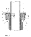
- This enlarged head portion (14) is shown in greater detail in figure (2 ).
- first annular recess (22) concentric with the bore of the main tubular body (6).
- This recess (22) opens out inwardly onto the bore and in effect comprises a larger diameter bore portion of the bore of the main tubular body (6), and channel/groove, within the flange (14).
- An annular collar (12) is fitted and located within this first recess (22).
- the annular collar (12) is fabricated from a resilient material, for example a rubber material such as for example EPDM (Ethylene Propylene Diene Monomer) a synthetic rubber.
- the inner diameter of the collar (12) is such that an inner surface of the collar tightly abuts against the outer surface of the installed post (2) such that there is a tight interference fit between the collar (12) and post (2).
- the inner surface (30) of the collar (12) includes a series of longitudinally spaced serrated circumferential ridges or teeth (31a,31b,31c) which project inwardly.
- the serrations (31a,31b,31c) are arranged and profiled such that they and the collar (12) provide greater resistance to longitudinal movement of the post (2) out of the socket (4) (i.e. upward) than to movement of the post (2) into the socket (i.e. downward).
- the serrations (31 a,31 b,31 c) have a triangular cross section and are arranged in a fir tree type arrangement in which an upper part of each serration (31a,31b,31c) is at a shallower tapering angle to the post (2) outer surface as compared to a lower portion of the each serration (31a,31b,31c).
- the post (2) can be more easily installed into the socket (4) whilst removal of the post (2) from the socket (4), for example by a vandal, is made more difficult.
- the collar (12) with the serrations (31a,31b,31c) provides a one way directional grip and enhanced interference fit upon the post(2). It will be appreciated though that other profiling of the collar (12) instead of the serrations (31a,31b,31c) illustrated could be used to provide this function in other embodiments.
- a second annular recess (20), in the form of a channel/groove formed in the end surface of the head portion (14), is defined within the head portion (14).
- the second recess (20) is similarly concentric with the bore of the main tubular body (6), and the first recess (22).
- This second recess (20) is radially separated from the first recess by a dividing wall portion (21) of the flange head portion (14).
- a strengthening band (8) in the form of an annular ring is located and fitted into the second recess (20). This strengthening or reinforcing band (8) is typically made from a material which is stronger than that of the remainder of the socket (4).
- the socket (4) could be fabricated from an injection moulded plastic material, for example athermoplastic such a polypropylene
- the strengthening band (8) could comprise 40% glass fibre reinforced compression moulded nylon material could be used for the strengthening band (8).
- the strengthening band (8) by virtue of its greater strength and also due to its continuous circumferential configuration, strengthens the upper region of the socket(4).
- the cap (10) closes off the upper longitudinal ends of the first and second recesses (22,20).
- the cap (10) is arranged to secure the strengthening band (8) and collar (12) within the recesses (22,20), and ensure that they are properly engaged therein.
- the cap when fitted to the socket (4), thereby prevents the strengthening band (8) and collar (12) from moving longitudinally (vertically upwards as shown) from and out of the socket (4).
- the cap (10) comprises a generally planar disc member with a central hole defined therein.
- the central hole within the cap (10) generally corresponds to the outer diameter of the post (2) such that the post (2) can be fitted through the central hole in the cap (10) and into the bore of the socket (4).
- the cap (10) is arranged to securely engage and be fitted to the head portion (14).
- a peripheral flange wall (25) depends from the periphery of the cap (10).
- the cap (10) is 'snap-fitted' onto the head portion (14).
- the cap (10) is pressed longitudinally onto the end of the flange head portion (14).
- the lip (24) on the peripheral flange (25) of the cap (10) rides over and longitudinally beyond the lip (26) on the outside of the head portion (14) with the peripheral flange (25) of the cap (10) flexing outwardly slightly to allow this.
- the engagement of the two cooperating lip projections (24,26) then secures the cap (10) onto the end of the head portion (14).
- the flange (25) of the cap (10) has to be prised outwards, using for example a screwdriver or other suitable tool, to allow the lip (24) to be eased back over the lip (26) on the head portion (14).
- fastening screws which are engaged within the head portion (14) could be used instead of or in addition to the snap fit arrangement.
- the use of fastening screws would provide a more secure engagement of the cap with the head portion although would add complexity to the arrangement.
- the heads of the fastening screws could have a non standard shape such that a specific 'key' tool is required for the screws.
- the cap (10) includes a further annular flange wall (28) projecting longitudinally from the cap (10). This flange wall (28), when the cap (10) is fitted to the head portion (14) fits, and is engaged, between the upper portion of the collar (12) and strengthening band (8) and continues the dividing wall portion (21) of the head portion (14).
- the fitting of the flange wall (28) between the collar (12) and strengthening band (8) when the cap (10) is fitted secures the upper portions of the strengthening band (8) and collar (12) radially in position within the socket assembly (4). This secures and further locks the strengthening band collar in position within the socket (4). In particular this also urges the collar (12) radially and increases the frictional engagement of the post (2) and collar (12) thereby increasing the grip on the post (2).
- the socket (4) is seated at the bottom of a hole excavated in the ground (1) and concrete (or other filling material) is poured into the hole around the socket (4) and allowed to set to hold the socket (4) in place in the ground (1).
- the head portion (14) of the socket (4) is positioned substantially level with the ground level.
- the strengthening band (8) and collar (12) are then fitted into the respective recesses in the socket (4).
- the strengthening band (8) and/or collar (12) may have already been fitted into the recesses (22,20) prior to installation of the socket (4) in the ground (1).
- the cap (10) is then fitted over the base of the post (2) with the post (2) passing though the central hole in the cap (10).
- the base of the post (2) is then inserted into and through the collar (12) and into the bore of the socket (4).
- the profiling and directional engagement of the serrations (31a,31b,31c) on the collar (12) mean that this insertion of the post (2) is relatively easy with the base of the post relatively easily passing through the collar (12).
- the upper portion of the collar (12) is not restrained by the dividing wall (21), the upper part of the collar (12) can deflect outwards such that is not urged into engagement with the post (2) so further allowing easy insertion of the post (2) through the collar (12).
- the post (2) is inserted into the socket (4) until the base of the post (2) is engaged upon the stud (18) at the bottom end of the socket (4).
- the cap (10) With the post (2) installed within the socket (4), the cap (10) is then slid longitudinally down the post (2) and onto the end of the head portion (14) of the socket (4). The cap (10) is then pressed home and snap fitted onto the end of the head portion (14) of the socket (4). The cap (10) thereby secures and ensures that the strengthening band (8) and collar (12) are engaged within the recesses (20,22) and into the head portion (14) of the socket (4).
- the flange (28) of the cap (10) as the cap (10) is fitted, fits and is inserted between the upper part of the collar (12) and strengthening band (8). As the cap (10) is fitted this urges and presses the collar (12) inwards and further into engagement with the post (2).
- the cap (10) secures and engages the collar (12) in place and within the socket (4) and thereby secures the post within the socket (4).
- the cap in effect when fitted, and by its engagement with the head portion (14) locks the strengthening band (8) and collar (12) in position within the socket (4) and the collar (12) into engagement with the post (2) to thereby secure the post (2) within the socket (4).
- the cap (10) is first prised way from and off the head portion (14) of the socket (4).
- the cap (10) can then be slid longitudinally upwards, away from and out of engagement with the socket (4).
- the post (2) is thereby at least partially released from the socket (4) and can be withdrawn from the socket (4).
- the post (2) As the post (2) is withdrawn the post (2) either slides out from the collar (12) and/or the collar (12) slides out of the recess (22) in the socket (4) along with the post (2). In the later situation the collar can then separately be removed (if necessary by cutting) from the post (2).
- the original post (2), or a replacement post (2) may be reinstalled and inserted into the original socket (4) in a similar manner to that described above. If necessary a new collar (12) can be used and fitted into the socket (4). In this way the mounting posts are securely fixed into the ground (1) whilst they can be removed and replaced simply and easily without necessitating extensive digging and breaking up of the ground.
- the post (2) can be more securely locked in place by engagement of the separate cap (10) with the socket (4).
- tighter gripping collars can be used without adversely preventing authorised disassembly and removal of the post. Consequently removal of the post (2) by vandals casually pulling on the post (2) is substantially prevented, whilst the post (2) can be easily removed by suitably equipped personnel first removing the cap (10) to release the post (2) and collar (12) from the socket (4).
- a further advantage of this arrangement is that the collar, strengthening band, and cap can all be individually replaced in the event of damage. If for example the post or street furniture which it mounts is hit be a vehicle a high impact load is applied to the head portion (14) of the socket (4) with the post (2) typically pivoting about the head (14) of the socket (2) about which the post (2) is mounted into the ground. In particular this impact load is most likely to cause the strengthening band (8), which reinforces the head portion (14) to fracture. With previous arrangements, the fracture or damage of the strengthening band or reinforcement embedded within the socket (4) would necessitate digging up of the ground and removal and of the entire socket (4). In contrast with this arrangement, the main socket (4) can be left in place and the strengthening band simply replaced within the recess (20). Similarly, if the cap (10) or collar is damaged they can also be individually and easily replaced.
- a yet further advantage of this arrangement is that it is considerably easier to fabricate than the prior arrangements.
- the socket (4) and cap is preferably made from injection moulded plastic.
- the strengthening band (8) and collar (12) are then installed as separate items within the finished moulded socket.
- the moulding of the socket without an embedded strengthening band (8) is considerably more straightforward than, as with the prior arrangements, having to mould the socket with an embedded band (8).
- Separate materials, optimised for the individual parts can also more readily be used since the various parts (socket body, strengthening band (8), collar (12) and cap (10)) are separate and discrete parts.
- the main tubular body (6) and main part of the socket are made from injection moulded polypropylene. This is easy to injection mould.
- the strengthening band (8) is made from 40% glass (either glass fibre or glass) reinforced compression moulded nylon to provide good strength.
- the collar is made from a EPDM, a synthetic rubber, to provide high frictional engagement and also a degree of resilience to securely grip the post. It will be appreciated though that other suitable materials and comminations of materials could be used in other embodiments
- the tubes used in a typical application are manufactured to generous tolerances and to provide a means for accommodating these variations the bore of the tubular main body portion (6) has been provided with a number (dependant on tube cross sectional shape of the tube) of longitudinal ridges (33), reference figure 3 (which is a cross sectional view of the tubular main body (6) suitable to receive a square section tube).
- the peaks of the ridges (33) represent the minimum size of the tube and if a slightly larger tube is fitted, then as it is forced into the tubular main body (6) it shaves the required amount off the peak of the ridges (33) to create a hole of dimensions that correspond to that particular tube. In variations of the pole housing that require higher levels of shock absorbency, this feature may be omitted.
- the pole housing In the case of the pole housing, the pole, when subjected to an impact, should be allowed to move whilst generating a force resisting that movement. Ideally, the optimum force produced should be only slightly less that the force necessary to cause failure of the pole.
- the head portion (14) essentially remains as previously described with the exception that the pole (2) is allowed to move more within the collar (12) to increase the amount of shock absorption.
- a compliant bush (34) is housed and retained in position by a cap (36) which is a snap fit into the base of the main tubular body (6).
- the pole (2) is a slide fit into the compliant bush (6) which firmly locates pole (2).
- the bush (34) has a chamfer (35) to aid location and retention of the pole.
- the bush (6) and collar (12) permit the pole to move whilst providing a considerable resistance to the movement and hence absorbing the impact load.
- the compliant bush (34) can have the force it produces to resist the impact load modified by varying the properties of the compliant material, such as hardness, and by changing the cross sectional profile.
- Figures 5 and 6 show compliant bush (34) with grooves (37) around the periphery. These have the effect of reducing the resistance to the impact.
- Different applications will employ tubes of different strengths and it is important to be able to adjust the properties of both the collar (12) and compliant bush (34) to achieve maximum shock absorption.
- the bush is replaceable.
- cap (10) is dispensed with and the collar (12) is replaced with a shock absorbing element (12') of a similar resilient material, such as an elastomer (EPDM).
- EPDM elastomer
- It has inclined top surfaces (40) to shed water away from the pole (2).
- a circumferential groove (42) capable of accepting an expansion ring (44), typically made of a plastics material such as nylon.
- the expansion ring (44) is "C"-shaped, and has a split (46) ( figure 9 ).
- the cross-sectional shape of the expansion ring (44) is generally wedge shaped (46) to aid penetration into the groove and to exert expansion forces on it. In order that the expansion ring (44) may be retained once inserted into the groove (42), its top edges (48) taper at a steeper angle than the wedge shape (46), thus acting to retain the ring in the groove.
- the strengthening band (8) in this embodiment is retained in the recess (20), and passing through the bore of the strengthening band (8) is a liner sleeve (50) which is an extension of the shock absorber element (12').
- the lower end of the liner sleeve (50) is provided with a lip (52) which retains the two components together, and when combined with the strengthening band (8) the two form a "cartridge" enabling them to be inserted and removed as a single unit.
- the top of the collar (12') interlocks with the top of the head portion (14) by means of a groove (54) in the collar and corresponding lip (56) of the top of the head portion (14).
- the "cartridge” comprising the collar (12') and strengthening band (8) (but without the expansion ring (44) in place) is slipped over the pole (2) and the pole inserted into the bore (6).
- the base of the pole locates by means of a chamfer (35) into the bush (34).
- the cartridge is pushed downwardly until the collar (12') locates on top of the head portion (14) with the lip (56) engaging in the groove (54).
- the expansion ring (44) is then forced into the circumferential groove (42), causing the top of the collar (12') to expand and press against both the post (2) and the top of the wall of the head portion (14).
- the strengthening band (8) is typically made of a glass fibre reinforced nylon material and is a slide fit into its recess (20) in the tubular portion (6).
- the socket assembly would comprise two internal bore sections and two collars (possibly joined into a single element).
- a single multiple post socket could also be produced.
Landscapes
- Engineering & Computer Science (AREA)
- Architecture (AREA)
- Civil Engineering (AREA)
- Structural Engineering (AREA)
- Refuge Islands, Traffic Blockers, Or Guard Fence (AREA)
- Coupling Device And Connection With Printed Circuit (AREA)
- Fittings On The Vehicle Exterior For Carrying Loads, And Devices For Holding Or Mounting Articles (AREA)
- Finger-Pressure Massage (AREA)
- Iron Core Of Rotating Electric Machines (AREA)
- Pharmaceuticals Containing Other Organic And Inorganic Compounds (AREA)
- Piles And Underground Anchors (AREA)
- Snaps, Bayonet Connections, Set Pins, And Snap Rings (AREA)
Claims (23)
- Dispositif (4) de montage de poteaux pour installation dans le sol d'un poteau (2) comprenant une partie (6) formant un corps tubulaire, conçue pour être installée dans le sol, et comportant une extrémité ouverte conçue pour recevoir un poteau (2) à soutenir, l'extrémité ouverte de la partie formant un corps tubulaire comprenant une partie (14) formant une bride agrandie définissant une partie de tête de la partie (6) formant un corps tubulaire principal, la partie (14) formant une bride de tête comprenant un collier résilient (12, 12') de retenue, conçu pour recevoir et pour retenir le poteau, et un anneau (8) de renfort ;
dans lequel la partie (14) de tête comprend un premier évidement (22) qui y est défini, dans lequel ledit collier (12, 12') est engagé et monté, un deuxième évidement (20) défini dans la partie de tête, conçu pour recevoir ledit anneau (8) de renfort, et l'ensemble étant conçu pour recevoir et pour maintenir le poteau, afin d'enfermer la partie (6) de corps tubulaire et de fixer le poteau (2) et l'anneau (8) de renfort, le collier (12, 12') et l'anneau (8) étant amovibles. - Dispositif selon la revendication 1, dans lequel une chape (10) est prévue pour s'adapter et s'engager avec ladite partie (14) de tête, afin de boucher les évidements (20, 22) et de fixer le collier (12) et l'anneau (8) de renfort en place.
- Dispositif de montage de poteaux selon la revendication 2, dans lequel la chape (10), quand elle est adaptée et engagée à la partie (14) de tête, est conçue pour pousser le collier (12) vers l'intérieur, en cours d'utilisation, en engagement avec le poteau (2).
- Dispositif de montage de poteaux selon la revendication 2 ou 3, dans lequel ladite chape (10) comprend une partie conçue, quand ladite chape est attachée à ladite partie de tête (14), coopère avec ledit évidement (22) pour pousser ledit collier (12), en cours d'utilisation d'engagement avec ledit poteau (2).
- Dispositif de montage de poteaux selon la revendication 4, dans lequel ladite chape comprend une saillie (28) de bride qui coopère avec ledit premier évidement (22) et avec une partie (14) de tête pour pousser le collier (12) en engagement avec ledit poteau (2) quand la chape est logée et en cours d'utilisation,
- Dispositif de montage de poteaux selon l'une quelconque des revendications 2 à 5, dans lequel le collier (12) comprend une surface (30) de butée permettant d'obtenir, en cours d'utilisation, un meilleur ajustement et une meilleure prise sur ledit poteau (2), contre le mouvement, dans une première direction par rapport au mouvement dans une deuxième direction,
- Dispositif de montage de poteaux selon la revendication 6, dans lequel ladite surface (30) de butée dudit collier comprend au moins une dentelure ou une nervure (31).
- Dispositif de montage de poteaux selon la revendication 7, dans lequel au moins des dentelures (31) sont orientées directionnellement, de sorte qu'une première surface de ladite dentelure vient en butée contre ledit poteau et selon un angle différent par rapport à une deuxième surface de ladite dentelure.
- Dispositif de montage de poteaux selon l'une quelconque des revendications 2 à 8, dans lequel ladite chape (10) est conçue pour être encliquetée sur ladite partie (14) de tête.
- Dispositif de montage de poteaux selon la revendication 9, dans lequel la chape (10) comprend un rebord (24) de bride qui est engagé de manière coopérante avec un rebord coopérant (24) de bride situé sur ladite partie (14) de tête.
- Dispositif selon la revendication 1, dans lequel le collier (12) comprend un élément (12') d'absorption de chocs présentant une rainure (42) à même de recevoir un anneau (44) de dilatation, afin de verrouiller l'élément (12') en place.
- Dispositif selon la revendication 11, dans lequel l'élément (12') d'absorption de chocs recouvre et rend étanche, en cours d'utilisation, l'ensemble de la partie supérieure de la partie (14) de tête.
- Dispositif selon l'une la revendication 11 ou 12, dans lequel l'élément (12') se verrouille avec la partie supérieure de la partie (14) de tête.
- Dispositif selon l'une quelconque des revendications 11 à 13, dans lequel l'anneau (8) de renfort est retenu entre le deuxième évidement (20) et une partie étendue (50) de manchon de l'élément (12').
- Dispositif de montage de poteaux selon l'une quelconque des revendications 1 à 14, dans lequel le poteau (2) et la partie (6) formant un corps principal tubulaire présentent globalement une coupe transversale circulaire.
- Dispositif de montage de poteaux selon l'une quelconque des revendications 1 à 14, dans lequel le poteau (2) et la partie (6) formant un corps principal tubulaire présentent globalement une coupe transversale carrée ou rectangulaire.
- Dispositif de montage de poteaux selon l'une quelconque des revendications précédentes, dans lequel ledit premier évidement (22) défini dans ladite partie (14) de tête est conçu pour que ledit collier (12, 12') puisse fléchir en s'écartant dudit poteau (2) en cours d'utilisation.
- Dispositif de montage de poteaux selon l'une quelconque des revendications précédentes, dans lequel le collier est fabriqué à partir d'un matériau élastique.
- Dispositif de montage de poteaux selon la revendication 18, dans lequel ledit collier est fabriqué à partir d'un matériau caoutchouteux.
- Dispositif de montage de poteaux selon l'une quelconque des revendications précédentes, dans lequel ladite partie (6) formant un corps tubulaire est fabriquée à partir d'une matière plastique moulée par injection.
- Dispositif de montage de poteaux selon la revendication 20, dans lequel ladite matière plastique est constituée de polypropylène.
- Procédé de construction d'un poteau impliquant un dispositif de montage de poteaux selon l'une quelconque des revendications précédentes, comprenant les étapes suivantes :a) installation dudit corps principal tubulaire (6) dans le sol,b) installation dudit anneau (8) de renfort dans ledit deuxième évidement (20),c) installation dudit collier (12, 12') dans ledit premier évidement (22),d) insertion d'une extrémité de base dudit poteau (2) à travers ledit collier (12, 12') et dans ladite partie (6) formant un corps tubulaire,e) logement de ladite chape (10) sur ladite partie (14) de tête, afin d'attacher ledit collier (12) au sein de ladite partie de tête, ou insertion dudit anneau (44) de dilatation dans l'élément (12') d'absorption de chocs.
- Procédé de construction d'un poteau selon la revendication 22, dans lequel ledit poteau (2) est inséré à travers ledit collier (12, 12') avant installation dudit collier et insertion dudit poteau dans ledit corps tubulaire principal (6).
Applications Claiming Priority (3)
| Application Number | Priority Date | Filing Date | Title |
|---|---|---|---|
| GB0216513 | 2002-07-17 | ||
| GBGB0216513.2A GB0216513D0 (en) | 2002-07-17 | 2002-07-17 | Post mounting arrangement |
| PCT/GB2003/003087 WO2004007844A1 (fr) | 2002-07-17 | 2003-07-16 | Systeme de montage de poteau |
Publications (2)
| Publication Number | Publication Date |
|---|---|
| EP1540085A1 EP1540085A1 (fr) | 2005-06-15 |
| EP1540085B1 true EP1540085B1 (fr) | 2010-03-17 |
Family
ID=9940567
Family Applications (1)
| Application Number | Title | Priority Date | Filing Date |
|---|---|---|---|
| EP03764021A Expired - Lifetime EP1540085B1 (fr) | 2002-07-17 | 2003-07-16 | Systeme de montage de poteau |
Country Status (8)
| Country | Link |
|---|---|
| US (1) | US7150579B2 (fr) |
| EP (1) | EP1540085B1 (fr) |
| AT (1) | ATE461321T1 (fr) |
| AU (1) | AU2003254466A1 (fr) |
| CA (1) | CA2493377A1 (fr) |
| DE (1) | DE60331742D1 (fr) |
| GB (2) | GB0216513D0 (fr) |
| WO (1) | WO2004007844A1 (fr) |
Families Citing this family (32)
| Publication number | Priority date | Publication date | Assignee | Title |
|---|---|---|---|---|
| US7788866B2 (en) * | 2002-11-09 | 2010-09-07 | Woodguard, Inc. | Method and apparatus for protecting a substrate |
| US7437857B1 (en) * | 2004-02-11 | 2008-10-21 | Spectrum Products, Llc | Compression anchor |
| US7779589B2 (en) * | 2005-03-31 | 2010-08-24 | Salman Mark T | Post anchor/adapter system |
| US7955022B2 (en) * | 2005-11-08 | 2011-06-07 | Thermoprene, Inc. | Elongate sleeve retention device and uses thereof |
| GB2435066A (en) * | 2006-02-09 | 2007-08-15 | Corus Uk Ltd | Safety barrier |
| WO2008154568A1 (fr) * | 2007-06-11 | 2008-12-18 | Mccue Corporation | Bollard semi-permanent |
| WO2010011638A1 (fr) * | 2008-07-25 | 2010-01-28 | Metro Industries Inc. | Système et dispositif pour empêcher la corrosion sur des montants d’angle de rayonnage |
| US20100077954A1 (en) * | 2008-10-01 | 2010-04-01 | Utility Pipeline, Ltd. | Removable gas line marker system |
| EP2435632B1 (fr) * | 2009-05-25 | 2014-04-23 | Seri Q Sign A/S | Ensemble d'ancrage pour mât déformable |
| US20110041752A1 (en) * | 2009-08-19 | 2011-02-24 | Lacivita Anthony | Anchorman marine mooring and docking system |
| US8360167B2 (en) * | 2010-08-11 | 2013-01-29 | Caterpillar Inc. | Composite seal for a hydraulic hammer |
| GB2482889A (en) * | 2010-08-18 | 2012-02-22 | Poletech Systems Ltd | Device for supporting a post comprising a sealing ring |
| WO2012139149A1 (fr) * | 2011-04-11 | 2012-10-18 | Smart Urban Pty Ltd | Dispositif de maintien de poteau, système de maintien de poteau et procédé pour maintenir un poteau à une profondeur variable |
| US9045903B2 (en) | 2011-05-24 | 2015-06-02 | Douglas Rawson-Harris | Pole assembly with transition ring |
| JP2014084642A (ja) * | 2012-10-24 | 2014-05-12 | Kyushu Sekisui Kogyo Co Ltd | 支柱保持管 |
| US10501929B2 (en) * | 2013-09-30 | 2019-12-10 | Drew P. HENRY | Hollow connector sleeve with interlocking components |
| US11280105B2 (en) * | 2017-01-09 | 2022-03-22 | Valmont Industries, Inc. | Prefabricated concrete pole base and method of installation |
| US10724202B2 (en) | 2017-01-11 | 2020-07-28 | Daniel S. Spiro | Cellular and ballasted universal pole foundation |
| US10633818B2 (en) | 2017-01-11 | 2020-04-28 | Daniel S. Spiro | Universal pole foundation with instant cap |
| US12503825B2 (en) | 2017-01-11 | 2025-12-23 | Exposure Illumination Architects, Inc. | Foundation structural design with cells configured to redirect and distribute stress loads |
| CN109505448B (zh) * | 2017-07-27 | 2020-06-30 | 杭州曼京科技有限公司 | 一种电力电网电线杆 |
| CN108179761B (zh) * | 2018-03-05 | 2023-08-11 | 台州伟立钢结构股份有限公司 | 一种建筑用钢结构基座 |
| US10344496B1 (en) * | 2018-04-24 | 2019-07-09 | Adam S. Cefalo | Anchoring device for a beach umbrella |
| US10767385B2 (en) * | 2018-09-17 | 2020-09-08 | Simon David Gray Wehr | Portable holder |
| DE202018106556U1 (de) * | 2018-11-19 | 2020-02-26 | Reinhard Bojahr | Vorrichtung zum Einsatz in einen Boden |
| FR3092601B1 (fr) * | 2019-02-08 | 2021-05-14 | Agritubel | Dispositif de protection de poteaux amovibles et système comprenant un tel dispositif |
| CA3149079A1 (fr) * | 2021-02-03 | 2022-08-03 | Ian Scott | Support de pole |
| US11814857B2 (en) * | 2021-02-05 | 2023-11-14 | Jarred Reinhardt | Sand anchor utilizing compressed gas |
| US12110701B2 (en) * | 2021-04-19 | 2024-10-08 | Brp Ventures, L.L.C. | Deck umbrella support system |
| ES2927157B2 (es) * | 2021-04-30 | 2023-03-07 | Road Steel Eng Sl | Dispositivo de union para poste de estructura soporte del equipamiento de vias de circulacion, y estructura soporte del equipamiento de vias de circulacion que incluye dicho dispositivo de union |
| KR102574424B1 (ko) * | 2022-03-24 | 2023-09-06 | 주식회사 편리한형제 | 확장 가능한 텐트 |
| US12523054B2 (en) * | 2023-08-22 | 2026-01-13 | Gary J. Schorr | Umbrella holding device |
Family Cites Families (12)
| Publication number | Priority date | Publication date | Assignee | Title |
|---|---|---|---|---|
| US1799314A (en) * | 1929-02-28 | 1931-04-07 | Pfaff & Kendall | Signpost support |
| DE2133278A1 (de) * | 1971-07-05 | 1973-01-18 | Konrad Nitsche | Bodenhuelse fuer pfaehle |
| SE391553B (sv) * | 1973-10-23 | 1977-02-21 | Granstroem Ab E | Anordning for forankring av stolpar eller master |
| DE2945092A1 (de) * | 1979-11-08 | 1981-05-21 | Helmut 7580 Bühl Linz | Halterung fuer stangen, wie schilder-,hinweis- o.ae. stangen |
| DE3733973A1 (de) * | 1987-10-08 | 1989-04-27 | Eberhard Hoeckle | Befestigungseinrichtung fuer einen verkehrszeichentraeger |
| DE3811401A1 (de) * | 1988-04-05 | 1989-10-26 | Cronenberg Ohg J | Abdeckbare bodenhuelse zur halterung eines mastes |
| FR2641557A1 (fr) * | 1989-01-11 | 1990-07-13 | Concept Urbain | Dispositif de fixation au sol de poteau ou potelet |
| AU664991B2 (en) | 1991-05-10 | 1995-12-14 | Poletech Systems Limited | Post installation |
| GB9211025D0 (en) * | 1992-05-22 | 1992-07-08 | Avon Polymer Prod Ltd | A post for a barrier or the like |
| AU2895995A (en) | 1994-07-13 | 1996-02-16 | David Ralph Marshall Hodges | Post installations |
| AU753702B2 (en) * | 1999-11-08 | 2002-10-24 | Automotive Safety Engineering Pty Ltd | Safety bollard |
| DE10015911B4 (de) * | 2000-03-30 | 2006-06-29 | Zf Sachs Ag | Axiale Sicherung zweier Bauteile mit einem Sicherungsring |
-
2002
- 2002-07-17 GB GBGB0216513.2A patent/GB0216513D0/en not_active Ceased
-
2003
- 2003-07-16 EP EP03764021A patent/EP1540085B1/fr not_active Expired - Lifetime
- 2003-07-16 CA CA002493377A patent/CA2493377A1/fr not_active Abandoned
- 2003-07-16 DE DE60331742T patent/DE60331742D1/de not_active Expired - Lifetime
- 2003-07-16 AU AU2003254466A patent/AU2003254466A1/en not_active Abandoned
- 2003-07-16 WO PCT/GB2003/003087 patent/WO2004007844A1/fr not_active Ceased
- 2003-07-16 US US10/521,525 patent/US7150579B2/en not_active Expired - Fee Related
- 2003-07-16 AT AT03764021T patent/ATE461321T1/de not_active IP Right Cessation
-
2005
- 2005-01-14 GB GBGB0500757.0A patent/GB0500757D0/en active Pending
Also Published As
| Publication number | Publication date |
|---|---|
| AU2003254466A1 (en) | 2004-02-02 |
| DE60331742D1 (de) | 2010-04-29 |
| CA2493377A1 (fr) | 2004-01-22 |
| US7150579B2 (en) | 2006-12-19 |
| WO2004007844A1 (fr) | 2004-01-22 |
| GB0500757D0 (en) | 2005-02-23 |
| US20060104715A1 (en) | 2006-05-18 |
| GB0216513D0 (en) | 2002-08-28 |
| ATE461321T1 (de) | 2010-04-15 |
| EP1540085A1 (fr) | 2005-06-15 |
Similar Documents
| Publication | Publication Date | Title |
|---|---|---|
| EP1540085B1 (fr) | Systeme de montage de poteau | |
| US5492429A (en) | Post installation | |
| US8376650B2 (en) | Bollard assembly | |
| US20050036851A1 (en) | Subgrade vault | |
| KR102605922B1 (ko) | 노면 결합력이 향상된 시선 유도봉 및 이의 시공 방법 | |
| JP2023541396A (ja) | 充電ステーションの基礎 | |
| KR100475463B1 (ko) | 도로 표지병 | |
| EP3710638B1 (fr) | Appareil de barrière routière pour la sécurité des cyclistes | |
| KR100758547B1 (ko) | 도로시설물 및 이의 설치방법 | |
| KR102306150B1 (ko) | 무볼트 차선분리대 및 이의 시공방법 | |
| CN216042986U (zh) | 一种水泥电杆基座 | |
| KR101055881B1 (ko) | 조립식 가로등 등주의 고정 구조 | |
| WO2007079520A1 (fr) | Chapeau et système raidisseur pour poteau de garde-corps | |
| KR100596932B1 (ko) | 록볼트용 고정장치 | |
| JP5377233B2 (ja) | 道路施設物設置用ナットアンカー、その施工方法、および道路施設物 | |
| KR200428458Y1 (ko) | 앵커볼트 보호캡 | |
| EP0770161A1 (fr) | Installation de poteaux | |
| EP2435632B1 (fr) | Ensemble d'ancrage pour mât déformable | |
| KR20090119139A (ko) | 원터치 제거식 네일구조 및 이를 이용한 보강철근 회수공법 | |
| KR100746633B1 (ko) | 맨홀 | |
| EP4675046A1 (fr) | Ensemble poteau d'etablissement de collision, liaison de retenue elastomere pour ensemble poteau et procede de protection contre les collisions pour poteau de signalisation | |
| KR20260000403U (ko) | 차량진입방지를 위한 볼라드 | |
| KR102958337B1 (ko) | 맨홀블록의 체결 구조 및 그 구조가 적용된 맨홀블록 조립체 | |
| CN218090646U (zh) | 一种防撞护栏 | |
| KR101138527B1 (ko) | 가로등 등주의 고정 구조 |
Legal Events
| Date | Code | Title | Description |
|---|---|---|---|
| PUAI | Public reference made under article 153(3) epc to a published international application that has entered the european phase |
Free format text: ORIGINAL CODE: 0009012 |
|
| 17P | Request for examination filed |
Effective date: 20050121 |
|
| AK | Designated contracting states |
Kind code of ref document: A1 Designated state(s): AT BE BG CH CY CZ DE DK EE ES FI FR GB GR HU IE IT LI LU MC NL PT RO SE SI SK TR |
|
| AX | Request for extension of the european patent |
Extension state: AL LT LV MK |
|
| DAX | Request for extension of the european patent (deleted) | ||
| GRAP | Despatch of communication of intention to grant a patent |
Free format text: ORIGINAL CODE: EPIDOSNIGR1 |
|
| GRAS | Grant fee paid |
Free format text: ORIGINAL CODE: EPIDOSNIGR3 |
|
| GRAA | (expected) grant |
Free format text: ORIGINAL CODE: 0009210 |
|
| AK | Designated contracting states |
Kind code of ref document: B1 Designated state(s): AT BE BG CH CY CZ DE DK EE ES FI FR GB GR HU IE IT LI LU MC NL PT RO SE SI SK TR |
|
| REG | Reference to a national code |
Ref country code: GB Ref legal event code: FG4D |
|
| REG | Reference to a national code |
Ref country code: CH Ref legal event code: EP |
|
| REG | Reference to a national code |
Ref country code: IE Ref legal event code: FG4D |
|
| REF | Corresponds to: |
Ref document number: 60331742 Country of ref document: DE Date of ref document: 20100429 Kind code of ref document: P |
|
| REG | Reference to a national code |
Ref country code: NL Ref legal event code: VDEP Effective date: 20100317 |
|
| PG25 | Lapsed in a contracting state [announced via postgrant information from national office to epo] |
Ref country code: FI Free format text: LAPSE BECAUSE OF FAILURE TO SUBMIT A TRANSLATION OF THE DESCRIPTION OR TO PAY THE FEE WITHIN THE PRESCRIBED TIME-LIMIT Effective date: 20100317 Ref country code: SI Free format text: LAPSE BECAUSE OF FAILURE TO SUBMIT A TRANSLATION OF THE DESCRIPTION OR TO PAY THE FEE WITHIN THE PRESCRIBED TIME-LIMIT Effective date: 20100317 Ref country code: AT Free format text: LAPSE BECAUSE OF FAILURE TO SUBMIT A TRANSLATION OF THE DESCRIPTION OR TO PAY THE FEE WITHIN THE PRESCRIBED TIME-LIMIT Effective date: 20100317 |
|
| PG25 | Lapsed in a contracting state [announced via postgrant information from national office to epo] |
Ref country code: SE Free format text: LAPSE BECAUSE OF FAILURE TO SUBMIT A TRANSLATION OF THE DESCRIPTION OR TO PAY THE FEE WITHIN THE PRESCRIBED TIME-LIMIT Effective date: 20100317 Ref country code: EE Free format text: LAPSE BECAUSE OF FAILURE TO SUBMIT A TRANSLATION OF THE DESCRIPTION OR TO PAY THE FEE WITHIN THE PRESCRIBED TIME-LIMIT Effective date: 20100317 Ref country code: RO Free format text: LAPSE BECAUSE OF FAILURE TO SUBMIT A TRANSLATION OF THE DESCRIPTION OR TO PAY THE FEE WITHIN THE PRESCRIBED TIME-LIMIT Effective date: 20100317 Ref country code: ES Free format text: LAPSE BECAUSE OF FAILURE TO SUBMIT A TRANSLATION OF THE DESCRIPTION OR TO PAY THE FEE WITHIN THE PRESCRIBED TIME-LIMIT Effective date: 20100628 Ref country code: BE Free format text: LAPSE BECAUSE OF FAILURE TO SUBMIT A TRANSLATION OF THE DESCRIPTION OR TO PAY THE FEE WITHIN THE PRESCRIBED TIME-LIMIT Effective date: 20100317 Ref country code: CY Free format text: LAPSE BECAUSE OF FAILURE TO SUBMIT A TRANSLATION OF THE DESCRIPTION OR TO PAY THE FEE WITHIN THE PRESCRIBED TIME-LIMIT Effective date: 20100317 Ref country code: GR Free format text: LAPSE BECAUSE OF FAILURE TO SUBMIT A TRANSLATION OF THE DESCRIPTION OR TO PAY THE FEE WITHIN THE PRESCRIBED TIME-LIMIT Effective date: 20100618 Ref country code: NL Free format text: LAPSE BECAUSE OF FAILURE TO SUBMIT A TRANSLATION OF THE DESCRIPTION OR TO PAY THE FEE WITHIN THE PRESCRIBED TIME-LIMIT Effective date: 20100317 |
|
| PG25 | Lapsed in a contracting state [announced via postgrant information from national office to epo] |
Ref country code: SK Free format text: LAPSE BECAUSE OF FAILURE TO SUBMIT A TRANSLATION OF THE DESCRIPTION OR TO PAY THE FEE WITHIN THE PRESCRIBED TIME-LIMIT Effective date: 20100317 Ref country code: BG Free format text: LAPSE BECAUSE OF FAILURE TO SUBMIT A TRANSLATION OF THE DESCRIPTION OR TO PAY THE FEE WITHIN THE PRESCRIBED TIME-LIMIT Effective date: 20100617 Ref country code: CZ Free format text: LAPSE BECAUSE OF FAILURE TO SUBMIT A TRANSLATION OF THE DESCRIPTION OR TO PAY THE FEE WITHIN THE PRESCRIBED TIME-LIMIT Effective date: 20100317 |
|
| PLBE | No opposition filed within time limit |
Free format text: ORIGINAL CODE: 0009261 |
|
| STAA | Information on the status of an ep patent application or granted ep patent |
Free format text: STATUS: NO OPPOSITION FILED WITHIN TIME LIMIT |
|
| PG25 | Lapsed in a contracting state [announced via postgrant information from national office to epo] |
Ref country code: DK Free format text: LAPSE BECAUSE OF FAILURE TO SUBMIT A TRANSLATION OF THE DESCRIPTION OR TO PAY THE FEE WITHIN THE PRESCRIBED TIME-LIMIT Effective date: 20100317 Ref country code: PT Free format text: LAPSE BECAUSE OF FAILURE TO SUBMIT A TRANSLATION OF THE DESCRIPTION OR TO PAY THE FEE WITHIN THE PRESCRIBED TIME-LIMIT Effective date: 20100719 |
|
| 26N | No opposition filed |
Effective date: 20101220 |
|
| PG25 | Lapsed in a contracting state [announced via postgrant information from national office to epo] |
Ref country code: MC Free format text: LAPSE BECAUSE OF NON-PAYMENT OF DUE FEES Effective date: 20100731 |
|
| REG | Reference to a national code |
Ref country code: CH Ref legal event code: PL |
|
| PG25 | Lapsed in a contracting state [announced via postgrant information from national office to epo] |
Ref country code: IT Free format text: LAPSE BECAUSE OF FAILURE TO SUBMIT A TRANSLATION OF THE DESCRIPTION OR TO PAY THE FEE WITHIN THE PRESCRIBED TIME-LIMIT Effective date: 20100317 |
|
| REG | Reference to a national code |
Ref country code: FR Ref legal event code: ST Effective date: 20110331 |
|
| PG25 | Lapsed in a contracting state [announced via postgrant information from national office to epo] |
Ref country code: CH Free format text: LAPSE BECAUSE OF NON-PAYMENT OF DUE FEES Effective date: 20100731 Ref country code: LI Free format text: LAPSE BECAUSE OF NON-PAYMENT OF DUE FEES Effective date: 20100731 |
|
| PG25 | Lapsed in a contracting state [announced via postgrant information from national office to epo] |
Ref country code: FR Free format text: LAPSE BECAUSE OF NON-PAYMENT OF DUE FEES Effective date: 20100802 |
|
| PGFP | Annual fee paid to national office [announced via postgrant information from national office to epo] |
Ref country code: IE Payment date: 20120130 Year of fee payment: 9 |
|
| PGFP | Annual fee paid to national office [announced via postgrant information from national office to epo] |
Ref country code: DE Payment date: 20120131 Year of fee payment: 9 |
|
| PGFP | Annual fee paid to national office [announced via postgrant information from national office to epo] |
Ref country code: GB Payment date: 20120127 Year of fee payment: 9 |
|
| PG25 | Lapsed in a contracting state [announced via postgrant information from national office to epo] |
Ref country code: LU Free format text: LAPSE BECAUSE OF NON-PAYMENT OF DUE FEES Effective date: 20100716 Ref country code: HU Free format text: LAPSE BECAUSE OF FAILURE TO SUBMIT A TRANSLATION OF THE DESCRIPTION OR TO PAY THE FEE WITHIN THE PRESCRIBED TIME-LIMIT Effective date: 20100918 |
|
| PG25 | Lapsed in a contracting state [announced via postgrant information from national office to epo] |
Ref country code: TR Free format text: LAPSE BECAUSE OF FAILURE TO SUBMIT A TRANSLATION OF THE DESCRIPTION OR TO PAY THE FEE WITHIN THE PRESCRIBED TIME-LIMIT Effective date: 20100317 |
|
| GBPC | Gb: european patent ceased through non-payment of renewal fee |
Effective date: 20120716 |
|
| PG25 | Lapsed in a contracting state [announced via postgrant information from national office to epo] |
Ref country code: DE Free format text: LAPSE BECAUSE OF NON-PAYMENT OF DUE FEES Effective date: 20130201 Ref country code: GB Free format text: LAPSE BECAUSE OF NON-PAYMENT OF DUE FEES Effective date: 20120716 |
|
| REG | Reference to a national code |
Ref country code: IE Ref legal event code: MM4A |
|
| PG25 | Lapsed in a contracting state [announced via postgrant information from national office to epo] |
Ref country code: IE Free format text: LAPSE BECAUSE OF NON-PAYMENT OF DUE FEES Effective date: 20120716 |
|
| REG | Reference to a national code |
Ref country code: DE Ref legal event code: R119 Ref document number: 60331742 Country of ref document: DE Effective date: 20130201 |