EP1540041B1 - Structure d'une electrode destinee a etre utilisee dans une cellule electrolytique - Google Patents
Structure d'une electrode destinee a etre utilisee dans une cellule electrolytique Download PDFInfo
- Publication number
- EP1540041B1 EP1540041B1 EP03792900A EP03792900A EP1540041B1 EP 1540041 B1 EP1540041 B1 EP 1540041B1 EP 03792900 A EP03792900 A EP 03792900A EP 03792900 A EP03792900 A EP 03792900A EP 1540041 B1 EP1540041 B1 EP 1540041B1
- Authority
- EP
- European Patent Office
- Prior art keywords
- anode
- cathode
- electrode
- frame
- wire mesh
- Prior art date
- Legal status (The legal status is an assumption and is not a legal conclusion. Google has not performed a legal analysis and makes no representation as to the accuracy of the status listed.)
- Expired - Lifetime
Links
Images

Classifications
-
- C—CHEMISTRY; METALLURGY
- C25—ELECTROLYTIC OR ELECTROPHORETIC PROCESSES; APPARATUS THEREFOR
- C25B—ELECTROLYTIC OR ELECTROPHORETIC PROCESSES FOR THE PRODUCTION OF COMPOUNDS OR NON-METALS; APPARATUS THEREFOR
- C25B11/00—Electrodes; Manufacture thereof not otherwise provided for
- C25B11/02—Electrodes; Manufacture thereof not otherwise provided for characterised by shape or form
- C25B11/03—Electrodes; Manufacture thereof not otherwise provided for characterised by shape or form perforated or foraminous
-
- C—CHEMISTRY; METALLURGY
- C02—TREATMENT OF WATER, WASTE WATER, SEWAGE, OR SLUDGE
- C02F—TREATMENT OF WATER, WASTE WATER, SEWAGE, OR SLUDGE
- C02F1/00—Treatment of water, waste water, or sewage
- C02F1/46—Treatment of water, waste water, or sewage by electrochemical methods
- C02F1/461—Treatment of water, waste water, or sewage by electrochemical methods by electrolysis
- C02F1/46104—Devices therefor; Their operating or servicing
-
- C—CHEMISTRY; METALLURGY
- C02—TREATMENT OF WATER, WASTE WATER, SEWAGE, OR SLUDGE
- C02F—TREATMENT OF WATER, WASTE WATER, SEWAGE, OR SLUDGE
- C02F1/00—Treatment of water, waste water, or sewage
- C02F1/46—Treatment of water, waste water, or sewage by electrochemical methods
- C02F1/461—Treatment of water, waste water, or sewage by electrochemical methods by electrolysis
- C02F1/467—Treatment of water, waste water, or sewage by electrochemical methods by electrolysis by electrochemical disinfection; by electrooxydation or by electroreduction
- C02F1/4672—Treatment of water, waste water, or sewage by electrochemical methods by electrolysis by electrochemical disinfection; by electrooxydation or by electroreduction by electrooxydation
-
- C—CHEMISTRY; METALLURGY
- C25—ELECTROLYTIC OR ELECTROPHORETIC PROCESSES; APPARATUS THEREFOR
- C25B—ELECTROLYTIC OR ELECTROPHORETIC PROCESSES FOR THE PRODUCTION OF COMPOUNDS OR NON-METALS; APPARATUS THEREFOR
- C25B11/00—Electrodes; Manufacture thereof not otherwise provided for
- C25B11/02—Electrodes; Manufacture thereof not otherwise provided for characterised by shape or form
-
- C—CHEMISTRY; METALLURGY
- C02—TREATMENT OF WATER, WASTE WATER, SEWAGE, OR SLUDGE
- C02F—TREATMENT OF WATER, WASTE WATER, SEWAGE, OR SLUDGE
- C02F1/00—Treatment of water, waste water, or sewage
-
- C—CHEMISTRY; METALLURGY
- C02—TREATMENT OF WATER, WASTE WATER, SEWAGE, OR SLUDGE
- C02F—TREATMENT OF WATER, WASTE WATER, SEWAGE, OR SLUDGE
- C02F1/00—Treatment of water, waste water, or sewage
- C02F1/001—Processes for the treatment of water whereby the filtration technique is of importance
-
- C—CHEMISTRY; METALLURGY
- C02—TREATMENT OF WATER, WASTE WATER, SEWAGE, OR SLUDGE
- C02F—TREATMENT OF WATER, WASTE WATER, SEWAGE, OR SLUDGE
- C02F1/00—Treatment of water, waste water, or sewage
- C02F1/24—Treatment of water, waste water, or sewage by flotation
-
- C—CHEMISTRY; METALLURGY
- C02—TREATMENT OF WATER, WASTE WATER, SEWAGE, OR SLUDGE
- C02F—TREATMENT OF WATER, WASTE WATER, SEWAGE, OR SLUDGE
- C02F1/00—Treatment of water, waste water, or sewage
- C02F1/28—Treatment of water, waste water, or sewage by sorption
-
- C—CHEMISTRY; METALLURGY
- C02—TREATMENT OF WATER, WASTE WATER, SEWAGE, OR SLUDGE
- C02F—TREATMENT OF WATER, WASTE WATER, SEWAGE, OR SLUDGE
- C02F1/00—Treatment of water, waste water, or sewage
- C02F1/46—Treatment of water, waste water, or sewage by electrochemical methods
-
- C—CHEMISTRY; METALLURGY
- C02—TREATMENT OF WATER, WASTE WATER, SEWAGE, OR SLUDGE
- C02F—TREATMENT OF WATER, WASTE WATER, SEWAGE, OR SLUDGE
- C02F1/00—Treatment of water, waste water, or sewage
- C02F1/46—Treatment of water, waste water, or sewage by electrochemical methods
- C02F1/461—Treatment of water, waste water, or sewage by electrochemical methods by electrolysis
- C02F1/46104—Devices therefor; Their operating or servicing
- C02F1/46109—Electrodes
- C02F2001/46119—Cleaning the electrodes
-
- C—CHEMISTRY; METALLURGY
- C02—TREATMENT OF WATER, WASTE WATER, SEWAGE, OR SLUDGE
- C02F—TREATMENT OF WATER, WASTE WATER, SEWAGE, OR SLUDGE
- C02F1/00—Treatment of water, waste water, or sewage
- C02F1/46—Treatment of water, waste water, or sewage by electrochemical methods
- C02F1/461—Treatment of water, waste water, or sewage by electrochemical methods by electrolysis
- C02F1/46104—Devices therefor; Their operating or servicing
- C02F1/46109—Electrodes
- C02F2001/46133—Electrodes characterised by the material
-
- C—CHEMISTRY; METALLURGY
- C02—TREATMENT OF WATER, WASTE WATER, SEWAGE, OR SLUDGE
- C02F—TREATMENT OF WATER, WASTE WATER, SEWAGE, OR SLUDGE
- C02F1/00—Treatment of water, waste water, or sewage
- C02F1/46—Treatment of water, waste water, or sewage by electrochemical methods
- C02F1/461—Treatment of water, waste water, or sewage by electrochemical methods by electrolysis
- C02F1/46104—Devices therefor; Their operating or servicing
- C02F1/46109—Electrodes
- C02F2001/46152—Electrodes characterised by the shape or form
- C02F2001/46157—Perforated or foraminous electrodes
-
- C—CHEMISTRY; METALLURGY
- C02—TREATMENT OF WATER, WASTE WATER, SEWAGE, OR SLUDGE
- C02F—TREATMENT OF WATER, WASTE WATER, SEWAGE, OR SLUDGE
- C02F2101/00—Nature of the contaminant
- C02F2101/30—Organic compounds
- C02F2101/308—Dyes; Colorants; Fluorescent agents
-
- C—CHEMISTRY; METALLURGY
- C02—TREATMENT OF WATER, WASTE WATER, SEWAGE, OR SLUDGE
- C02F—TREATMENT OF WATER, WASTE WATER, SEWAGE, OR SLUDGE
- C02F2101/00—Nature of the contaminant
- C02F2101/30—Organic compounds
- C02F2101/36—Organic compounds containing halogen
- C02F2101/363—PCB's; PCP's
-
- C—CHEMISTRY; METALLURGY
- C02—TREATMENT OF WATER, WASTE WATER, SEWAGE, OR SLUDGE
- C02F—TREATMENT OF WATER, WASTE WATER, SEWAGE, OR SLUDGE
- C02F2103/00—Nature of the water, waste water, sewage or sludge to be treated
- C02F2103/008—Originating from marine vessels, ships and boats, e.g. bilge water or ballast water
-
- C—CHEMISTRY; METALLURGY
- C02—TREATMENT OF WATER, WASTE WATER, SEWAGE, OR SLUDGE
- C02F—TREATMENT OF WATER, WASTE WATER, SEWAGE, OR SLUDGE
- C02F2103/00—Nature of the water, waste water, sewage or sludge to be treated
- C02F2103/30—Nature of the water, waste water, sewage or sludge to be treated from the textile industry
-
- C—CHEMISTRY; METALLURGY
- C02—TREATMENT OF WATER, WASTE WATER, SEWAGE, OR SLUDGE
- C02F—TREATMENT OF WATER, WASTE WATER, SEWAGE, OR SLUDGE
- C02F2201/00—Apparatus for treatment of water, waste water or sewage
- C02F2201/46—Apparatus for electrochemical processes
- C02F2201/461—Electrolysis apparatus
- C02F2201/46105—Details relating to the electrolytic devices
- C02F2201/4612—Controlling or monitoring
- C02F2201/46125—Electrical variables
- C02F2201/4613—Inversing polarity
-
- C—CHEMISTRY; METALLURGY
- C02—TREATMENT OF WATER, WASTE WATER, SEWAGE, OR SLUDGE
- C02F—TREATMENT OF WATER, WASTE WATER, SEWAGE, OR SLUDGE
- C02F2303/00—Specific treatment goals
- C02F2303/04—Disinfection
-
- C—CHEMISTRY; METALLURGY
- C02—TREATMENT OF WATER, WASTE WATER, SEWAGE, OR SLUDGE
- C02F—TREATMENT OF WATER, WASTE WATER, SEWAGE, OR SLUDGE
- C02F9/00—Multistage treatment of water, waste water or sewage
Definitions
- the present invention relates to a structure of an electrode for use as an anode/cathode in an electrolytic cell as stated in the preamble of the following patent claim 1.
- the invention relates to a method for preparing said electrode structure.
- the invention also relates to a use of the electrolytic cell including anode and cathode as mentioned above.
- the invention relates to the technology concerning the production of oxidants and radicals which are used to oxidising and eliminating organic material in liquids, and organic materials on particles in liquids, and for destruction of bacteria, spores, micro organisms, algae and virus.
- Electrodes are produced by the use of electrolytic coating a substrate with thin layers of precious (noble) metals.
- precious (noble) metals have a particularly short lifetime and they do not tolerate being exposed to high voltages over time. If they are exposed to high voltages they will burn. During the process a dissolving/precipitation occurs from the anode so that it is corroded.
- tantalum, iridium, or a mixture of these are rolled down to between 0,015 and 0,035 mm and is welded to a core for an anode which is made of titanium, aluminium or copper.
- a frictional welding is used.
- the lifetime for these electrodes is longer than of the electrodes that are made by use of electrolysis. They tolerate substantially higher voltage and current.
- the known electrolytic processes in its simplest form provide Cl 2 as an oxidation agent. Further oxidants (ClO 3 - , O 3 , O 2 , H 2 O 2 , OH, ClOH, O) are however far more chemically reactive, and are provided by coating a substrate with precious metals where a voltage is exposed in a range where the law of Farraday is exceeded.
- the radicals are in particular the most powerful oxidation agents, both with regard to power and non-desirable side-effects (halogenated compounds of organic material).
- the problem of the known electrolytic processes is that the radicals cannot be utilised since they have a lifetime of a thousandth of a second and are therefore only present very close to the surface of the anode.
- the radicals cannot be utilised since they have a lifetime of a thousandth of a second and are therefore only present very close to the surface of the anode.
- large amounts of liquids cannot effectively be exposed to radical exposure for reaction with organic compounds, bacteria, virus etc, which is desired to be eliminated from the liquid.
- US patent 6,342,151 comprises anodes/cathodes made of permeable conductive material selected from the group consisting of perforated plates, screens, wool, felt and weave made of stainless steel, aluminium, copper, platinized titanium, mixed metal oxides, gold and gold plated steel. Also this electrode use spacers to prevent shortcut between anode and cathode when distance between said components are small.
- an object of invention to provide a new an improved construction of an electrode where a reduced oxidation effect due to hydrogen interference between anode and cathode, and on the cathode, may be eliminated.
- radicals are the predominant oxidation agent, also with regard to non-desirable side effects of further oxidation agents, it is essential for inventiveness, compared with the state of art technology, that the radical effects on the materials to be disinfected/oxidised, are considerably increased.
- a method is provided which is suitable in using wire, knitted, woven or plaited wire mesh net of metals for use for, and production of an anode and/or a cathode which may be used to produce a mixture of oxidants, and in particular radicals by use of electrolysis.
- the invention is characterised in that an anode is assembled with wires or wire mesh, knitted or plaited of tantalum, niobium, hafnium, zirconium, platinum, rhodium, iridium, ruthenium, palladium, or an alloy thereof, or a mixture of different wires of the abovementioned metal.
- the invention is characterised in that the cathode is assembled with wires or a wire mesh, knitted or plaited of 316L steelwires, or higher alloyed conductive and resistant material.
- the invention is characterised in that the wires or anode meshs and cathode meshs may be joined close together without short circuit contact in that a separation mesh, membrane or coarse crossed squared mesh in a non-conductive oxidant resistant material, which is arranged between the anode and cathode in order to separate these to prevent a short circuit contact.
- a superior conductive material may be arranged on the anode and cathode, individually or in a coarse square pattern, and may be thereafter insulated by means of oxidant durable insulating material from electrolyte in order to provide an even current through flow over the exposed wire mesh or wire net area.
- the invention is characterised in that anode/cathode is arranged in a flow of liquid which has to pass through the anode/cathode, or that the anode/cathode is arranged in a vessel for production of oxidant.
- the invention is characterised in that by electrolysing of freshwater one is able to use both cathode mesh and anode mesh in SS316L quality or higher alloyed metal.
- the invention is characterised in that by electrolysis of freshwater a woven, knitted or plaited mesh may be replaced with a plate in SS316L which is perforated by means of photochemistry in order to substitute a wire mesh.
- the present invention differs from existing electrolytic cells/processes where the effect of radicals, ozone, hydrogen peroxide, chlordioxide, and hypochlorite is prepared from anodes with a layer of precious metals which produces the reactive oxidants, and by providing an electrode structure whereby the production of radicals may be utilised more optimally than previously.
- anode having a shape including a mesh of metal as disclosed, having a wire distance of from 100 micron to 25000 micron or a square opening of from 18 micron to 25000 micron where the metal is exposed to voltages exceeding the law of Farraday resulting in a high production of oxidant close to the anode.
- the liquid to be handled is brought to pass a wire net mesh where the opening in the wire mesh has an opening size of minimum 15 micron (15 ⁇ m).
- the radical reaction with a lifetime of some thousandth of a second, will act substantially on all the liquid flowing through the wire mesh.
- Other electrolytic oxidation processes obtain 1-3% radical effect on the surface of the anode.
- the present invention one obtains an efficiency of 95-98% utilisation of the radical effect. This is due to the fact that up to 95-98% of the liquid is passing close to the anode where the radicals spend their lifetime in that the liquid in fact flows through the fine-meshed anode.
- the present invention differs from the existing electrolytic cells/processes in that the anode and the cathode may be conducted very close together by means of a separation element (spacer) or a separation wire mesh, prepared by a coarse squared non-conducting material.
- a separation element spacer
- a separation wire mesh prepared by a coarse squared non-conducting material.
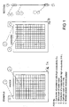
- each frame is covered by two layers of wire mesh, on layer of each plane side of the frame. It is however sufficient that the frame includes only one wire mesh layer, as shown in figure 1A, 1B and 1C.
- a wire mesh or parallel threads, 12 and 14, respectively is bounded to each side of the conductor frame 10 by exposing it to a substantial tension force/pressure and possibly by applying heat and using a bonding agent, or by induction welding or laser welding simoultaneously with that wire or perforated foil is kept under sufficient tension.
- the wires or mesh covering the exposed area on each plane side of the conductor are stabilized.
- the wire mesh includes parallel threads where each tenth or twentieth thread is of tantalum while the others are platinum threads.
- a spacer foil 16 (of a PVS or polypropylene material) of a non-conducting material, and having the exact shape (plane view) of the frame 10, is positioned and anchored.
- the openings 18 of the separation wire mesh 16 are aligned with the through flow openings 18 of the frame 10.
- the thickness of the frame 10 may be 5 mm, while the spacer foil 16 may have a thickness as low as 0,3 mm (representing the separation between the anode and cathode surfaces).
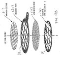
- an electrode unit for an anode or cathode, includes said conductive frame having a number of through flow openings 18, both plane sides of which being covered with the perforated plate, the wires (parallel threads or a wire mesh), and the spacer foil 18 on one side only. Further the conductive frame (for a cathode or anode) 10 includes means 20 for connecting to adequate current supply (voltage and current).
- two electrode units as shown in figure 4 are mounted mutually close to each other in alignment, so that said spacer layer 18, provides for the necessary distance (for example of 0,3 mm) between the anode surface 14 of one electrode unit and the cathode surface 12 of the adjacent electrode unit.
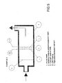
- An electrolytic cell consisting of a number of the abovementioned pairs of electrode units (up to 50 pairs), may have a circular, or rectanuglar shape.
- a circular electrode unit may for example have a diameter of up to 1 meter, representing the water through flow of the unit.
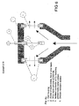
- the electrolytic cell may be placed into a pipe conducting the water to be treated according to the invention, for example as shown i figure 5.
- the process water flowing through the unit (the openings 18) of the wire mesh of the unit obtains a close reactive contact with the oxidants and radicals formed on the anode threads of the wire mesh.
- the drawing figures 4A and 4B are expanded views (rectangular and circular versions) of the four layers 20, 12, 14, 16 of which each unit is structured.
- Fig. 4B shows the anode or cathode wire mesh where the conductor frame of a superior rigid conductive material is supporting the exposed anode or cathode surface in order to obtain an even current distribution over a large area or in case of high current.
- the mesh is attached to the conductor frame at both sides.
- the non-conductive spacing material in the same shape as the rigid conductor frame and attached to one of the meshes at one side.
- the assembly of a single anode or cathode can be stacked in numbers from one anode and one cathode up to 50 altogether.
- Anode and cathode might be of identical material or different. In case of similar material DC power applied might be alternated to avoid scaling and uneven tear and wear.
- Anode size might each be more than 1 m diameter.
- Flow capacity might be from a few litres /hr in the smallest cells to more than 1000 m3/hr in each of the largest cell.
- Typical current density at 316L anodes is 38 mA/cm2 provided Cl content at 5 ppm. For noble metals the above have been tested to 270 Amp at a anode area of 0,5 cm2.
- the wire-mesh may be formed of individual wires mounted parallel to one another to the frame, or of individual wires that are woven, knitted or plaited or induction-welded to form the aforementioned mesh.
- each individual wire or the perforated foil is attached to the conducting frame such that electrical contact is achieved for even current distribution over exposed electrode area and exposed electrode area becomes tension stabilised to eliminate use of conventional spacer, whereupon frame or conductor is isolated from the liquid electrolyte by an oxidant-resistant isolator/coating.
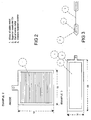
- liquid After the liquid has processed according to the invention it is directed through an hydrophobic adsorption filter or hydrophobic adsorption media in order to remove potential excess organic compounds.
- the liquid is preferably directed through a flotation device in order to remove electro flotated organic material.
- the exposed gap between anode and cathode have no need for conventional or further spacers, as spacing is provided by applying a foil, membrane or coarse of non conductive material of the same shape as the frame itself.
- the clearance might be as low as 0,3 mm. This implies that by the invention, it is possible to obtain a high current density with a very low voltage, something which involve that the Law of Farraday easily is exceeded without flow or current loss due to spacer and a desired production of reactive oxidants is provided.
- wire/mesh or perforated foil at both sides of the conductor frame is that it allows mm2 uppscaling for extreme currents passing to the exposed area for electrolysis.
- a 5mm thick frame covered at both sides allows placement of a thin spacing frame at both sides where the cathode mesh/perforated foil can be placed close to the anode in a distance down to 0,3 mm. With varying distances more than 3000 Amps can be passed through an electrode.
- the present invention differs from existing electrolytic cells/processes in that one by means of a very low voltage, may obtain the necessary high current density of large area without this reducing the volume through flow of the liquid to be handled. This also implies that large volumes of liquid to be handled may be treated very cheaply.
- the volume capacity of the electrolytic cell is not changed in contrast to other electrolytic cells even though the distance between the anode and cathode is reduced from i.e. 5 cm to 0,3 mm in that the same volume-liquid flow goes through the anode and cathode independent of the mutual distance between them.
- the present invention differs from the existing anodes in that the use of wires to a considerable degree increases the area of the anode compared to the weight of the metal and the real surface. Thus, the costs of the precious metals are also reduced considerably at the same time as the efficiency per cm 2 , is increased.
- the present invention differs from existing electrolytic cells/processes in that it is possible to obtain high current density, a low consumption of energy and a high through flow by volume of liquid, as the distance between the anode and cathode can be reduced to 0,3 mm without this reducing the capacity of the electrolytic cell, so that it may be used with the ion conductivity in fresh water (surface water and ground water).
- an anode mesh of tantalum including some wires of another precious metal from the platinum group produces mainly ozone, radicals and hydrogen peroxide, and very little hypo chlorite and chloride dioxide. This is due to the fact that all flow of current will take place from the precious metal wires such as tantalum immediately will immediately obtain an isolating layer of oxide.
- the present invention differs from existing electrolytic cells/processes in that it can be used with a low cost for treating large volumes of liquid, such as surface water, fresh water and ground water with the composition existing in great parts of the world today. Even with both anode and cathode of 316 L steel or higher alloyed metal without the anode oxidising or corroding. This is due to a high electrode surface with very low consumption of energy is producing the necessary oxidant (ozone and radicals) even with the average conductivity in ground water and surface fresh water.
- the present invention is characterised in that liquid may be conducted through anode and cathode in that a frame of conductive material is fixed to the anode and cathode mesh with sufficient contact, the mesh is preferably conducted at both sides of the frame, and the conductor frame is coated with a non oxidizable material in order to protect against contact with electrolyte.
- the spacing material in a non-conductive oxidant resistant material may be provided whereafter the anode or cathode mesh is assembled.
- the spacing material is of identical shape as the conductor frame and of varying thickness.
- the structure shown in fig. 5 was used in control and verified experiments for treating the ballast water from ships and including sea water containing bacteria, micro organism, algae and spores.
- the water including a high degree of pollution was conducted through the cell once, as shown by arrows, with an amperage of 100 A.
- the result show that 100% of the abovementioned pollutants, including spores, where destroyed.
- An extrapolation of the results based on the experiments show that the required consumption of energy will be 5kWh in order to handle 2500 m3/h process water with an anode surface of 2,5 m 2 .
- Fig. 6 shows a section of an electrolytic cell there foil or wire mesh to which a liquid was added to both the plain surfaces whereupon the liquid is conducted through the cathode on each side of the anode so that hydrogen does not come in contact with the anode or in the field between the anode and cathode.
- This electrolytic cell was used for destruction of poly aromatic hydrocarbons (PAH) and PCB on particles in a sea water slurry. With a careful addition of electrolyte and circulation of the mixture during 20 minutes, the PAH-content was reduced by 99,6% and the PCB-content was reduced by 76% based on relatively high concentrations.
- PAH poly aromatic hydrocarbons
- PCB-content was reduced by 76% based on relatively high concentrations.
- An electrode stack as described in Figure 4B comprising 5 anodes and 6 cathodes all of 316 L steel and a total anode area of 1013 cm2 were assembled with a 1 mm spacer as described in fig. 4.
- the liquid flow through the cell was at a rate of 10 1/min.
- Effluent was untreated drinking water from a surface source with salinity varying between 1,5 and 5 ppm, and with high humic content.
- E-coli bacteria were added to the water at a concentration of 560.000 bacterias/ml. Passed once through the cell with current 20 Amp showed a total disinfection effetness in all samples taken after treathment. That is sample series taken between 2 and 20 minutes after passed trough the cell.
- Drill cuttings from oil and gas industry was processed through an electrode under conditions as described in EXAMPLE 4. The cuttings was disperged into 221 of effluent containing 6 % NaCl. Scope was to remove Hydrocarbons from particles. Initial content of 7,62% total Hydrocarbon vas reduced to 1.32 % in an hour processing.
- Deep blue textile dying wastewater was passed through an anode of noble metal threads stretched across a 5 inch diameter sircular anode conductor frame so that the area of anode only was 0,5 cm2 total.
- the 2 cathodes was wire mesh of 316L steel. 20 l was batch proccesed with flow 180 l/min through the electrode. Volume 20 l. NaCl oontent 5%. Current was 270 Amp. In 25 to 35 seconds the waste water became blank.
Claims (25)
- Structure d'électrode en matière électriquement conductrice destinée à servir d'anode et/ou de cathode dans une cellule électrolytique, et comprenant un moyen d'espacement servant à éviter un contact électrique entre électrodes pendant l'utilisation, et conçue pour permettre le passage d'un liquide à traiter tel que de l'eau, caractérisée par
un cadre conducteur (10) comportant un certain nombre d'ouvertures (18) de passage de liquide et
comportant un moyen (20) de connexion à une source d'alimentation en courant électrique,
le fait qu'une seule ou les deux faces planes du cadre (10) est/sont couvertes par une feuille perforée ou un treillis métallique conducteurs (12, 14), et
le fait que le moyen d'espacement (16) est une feuille perforée ou un treillis métallique conçu pour couvrir l'une des surfaces planes de la feuille perforée ou d'un treillis métallique (12, 14), et la section plane de ladite feuille d'espacement correspond principalement à la section plane du cadre (10). - Structure d'électrode selon la revendication 1, caractérisée en ce que le treillis métallique ou le grillage métallique (12, 14) comporte des brins parallèles, un brin sur dix ou sur vingt étant un fil en tantale tandis que les brins intermédiaires sont en platine.
- Structure selon les revendications 1 et 2,
caractérisée en ce que les fils du treillis métallique (12, 14) sont individuellement espacés les uns des autres de 100 micromètres à 25000 micromètres et, s'ils sont tissés, tricotés, soudés par induction ou tressés sous la forme d'un treillis, comportent une ouverture de 15 micromètres à 25000 micromètres pour le passage d'air. - Structure selon l'une quelconque des revendications précédentes, caractérisée en ce que chaque fil a un diamètre de 0,010 mm à 5 mm.
- Structure selon l'une quelconque des revendications précédentes, caractérisée en ce que la feuille ou un treillis métallique (12, 14) est constitué de tantale, de niobium, d'hafnium, de zirconium, de platine, de rhodium, d'iridium, de ruthénium, de palladium ou de n'importe quel alliage de ceux-ci, ou d'un alliage ou d'une composition de fils des différents métaux précités.
- Structure selon l'une quelconque des revendications précédentes, caractérisée en ce que l'électrode (12, 14) en feuille est constituée d'une plaque d'un alliage métallique SS 316 L ou d'un type supérieur, perforée de manière serrée par photochimie.
- Structure selon l'une quelconque des revendications précédentes, caractérisée en ce que les ouvertures de passage (18) du moyen d'espacement (16) sont alignées avec les ouvertures de passage (18) du cadre (10).
- Structure selon l'une quelconque des revendications précédentes, caractérisée en ce que la feuille d'espacement (16) est une feuille de PVC ou de polypropylène et est soudée au cadre (10).
- Structure selon l'une quelconque des revendications précédentes, caractérisée en ce que l'épaisseur du cadre (10) est d'environ 5 mm.
- Structure d'électrode selon l'une quelconque des revendications précédentes, caractérisée en ce que le cadre (20) est couvert d'une matière non oxydable afin d'assurer une protection contre un contact avec le liquide de traitement précité.
- Structure selon l'une quelconque des revendications précédentes, caractérisée en ce que l'épaisseur de la feuille est de 25 à 1000 micromètres et le diamètre de chaque perforation est de 25 à 2000 micromètres.
- Procédé de fabrication d'une électrode selon la revendication 1, caractérisé en ce que des feuilles perforées ou des treillis métalliques (12, 14, 16) sont accrochés au cadre (10) en soumettant les feuilles perforées ou les treillis métalliques à une force d'étirement ou de traction, puis en les poussant contre et en les fixant à la surface du cadre par soudage et/ou collage.
- Procédé selon la revendication 12, caractérisé en ce que les feuilles perforées ou les treillis métalliques (12, 14, 16) sont accrochés au cadre (10) par soudage par friction, soudage laser ou de préférence par compression/chauffage et collage et exposition de la feuille ou du treillis métallique à ladite force de traction suffisante.
- Utilisation de la structure d'électrode selon les revendications 1 à 11, dans une cellule électrolytique où des électrodes individuelles selon lesdites revendications sont empilées et interconnectées pour former des paires anode/cathode au nombre de 1 à 50 inclusivement les unes avec les autres à l'intérieur d'un tube, pour le traitement de liquides/d'eau amenés à passer à travers les paires d'électrodes de la cellule dans le tube, un courant étant appliqué à chaque paire composée d'une anode et d'une cathode.
- Utilisation de la structure d'électrode selon la revendication 14 dans une cellule électrolytique traitant des liquides/de l'eau, où l'anode et la cathode sont en matière identique ou différente, et, en cas de matière identique, un courant continu c.c. appliqué pourrait être alterné pour éviter un écaillement et des déchirures et une usure irrégulières.
- Utilisation de la structure d'électrode selon l'une quelconque des revendications 14 et 15 dans une cellule électrolytique traitant des liquides/de l'eau, la capacité de passage pouvant être de quelques litres/heure et atteindre plus de 1000 m3/heure.
- Utilisation de la structure d'électrode selon les revendications 14 à 16 dans une cellule électrolytique traitant des liquides/de l'eau, la densité normale du courant au niveau d'anodes en matière 316L étant de 38 mA/cm2 en supposant une teneur en C1 de 5 ppm, et pour des métaux nobles l'intensité étant de 270 Amp sur une surface d'anode de 0,5 cm2, et la distance entre la surface de l'anode d'un ensemble d'électrodes et la surface de cathodes de l'ensemble d'électrodes voisin pouvant être d'environ 0,3 mm.
- Utilisation de l'anode et de la cathode selon les revendications précédentes 14 à 17, dans une cellule électrolytique, pour produire par électrolyse des oxydants, pour l'oxydation d'une matière organique dans des liquides, et d'une matière organique sur des particules dans des liquides.
- Utilisation de l'anode et de la cathode selon les revendications précédentes 14 à 18, dans une cellule électrolytique, pour la production d'oxydants par électrolyse, pour l'oxydation et la destruction de bactéries, de spores, de microorganismes, d'algues et de virus dans des liquides.
- Utilisation de l'anode et de la cathode selon les revendications précédentes 14 à 19, dans une cellule électrolytique, pour la production d'oxydants par électrolyse, pour le traitement d'eau douce et d'eau potable.
- Utilisation de l'anode et de la cathode selon les revendications précédentes 14 à 20, dans une cellule électrolytique, dans laquelle un liquide/de l'eau pollué est amené à passer par les ouvertures de passage (18) de l'anode et de la cathode de la cellule.
- Utilisation de l'anode et de la cathode selon les revendications précédentes 14 à 21, dans une cellule électrolytique, pour la production d'oxydants par électrolyse, pour la destruction de virus, de spores, de bactéries, de microorganismes, d'algues et de sporocystes d'algues de dimensions inférieures à 100 micromètres dans des eaux de lestage de navire.
- Utilisation de l'anode et de la cathode selon les revendications précédentes 14 à 22, le liquide à traiter, avant son traitement selon l'invention, étant dirigé pour passer dans un extracteur mécanique de particules afin d'éliminer la totalité des particules et organismes de dimensions plus grandes que celles des ouvertures de passage d'air de l'électrode.
- Utilisation de l'anode et de la cathode selon les revendications précédentes 14 à 23, dans laquelle le liquide qui a été traité, après son traitement selon l'invention, est dirigé de manière à passer dans un filtre hydrophobe d'adsorption ou un support hydrophobe d'adsorption afin d'éliminer d'éventuels excédents de composés organiques.
- Utilisation de l'anode et de la cathode selon les revendications précédentes 14 à 24, dans laquelle le liquide en cours de traitement est dirigé de manière à passer dans un dispositif de flottation afin d'éliminer la matière organique en électroflottation.
Applications Claiming Priority (3)
| Application Number | Priority Date | Filing Date | Title |
|---|---|---|---|
| NO20024054A NO321256B1 (no) | 2002-08-26 | 2002-08-26 | Elektrodekonstruksjoner, samt anvendelse derav |
| NO20024054 | 2002-08-26 | ||
| PCT/NO2003/000296 WO2004018733A2 (fr) | 2002-08-26 | 2003-08-26 | Structure d'une electrode destinee a etre utilisee dans une cellule electrolytique |
Publications (2)
| Publication Number | Publication Date |
|---|---|
| EP1540041A2 EP1540041A2 (fr) | 2005-06-15 |
| EP1540041B1 true EP1540041B1 (fr) | 2006-06-14 |
Family
ID=19913935
Family Applications (1)
| Application Number | Title | Priority Date | Filing Date |
|---|---|---|---|
| EP03792900A Expired - Lifetime EP1540041B1 (fr) | 2002-08-26 | 2003-08-26 | Structure d'une electrode destinee a etre utilisee dans une cellule electrolytique |
Country Status (17)
| Country | Link |
|---|---|
| US (1) | US7611611B2 (fr) |
| EP (1) | EP1540041B1 (fr) |
| JP (1) | JP2005536639A (fr) |
| KR (1) | KR20050057009A (fr) |
| CN (1) | CN100537849C (fr) |
| AT (1) | ATE330044T1 (fr) |
| AU (1) | AU2003263684A1 (fr) |
| BR (1) | BR0313935A (fr) |
| CA (1) | CA2536815A1 (fr) |
| DE (1) | DE60306172T2 (fr) |
| DK (1) | DK1540041T3 (fr) |
| EA (1) | EA010551B1 (fr) |
| ES (1) | ES2266900T3 (fr) |
| MX (1) | MXPA05002211A (fr) |
| NO (1) | NO321256B1 (fr) |
| PL (1) | PL374540A1 (fr) |
| WO (1) | WO2004018733A2 (fr) |
Families Citing this family (40)
| Publication number | Priority date | Publication date | Assignee | Title |
|---|---|---|---|---|
| CN1197786C (zh) * | 2003-06-13 | 2005-04-20 | 大连海事大学 | 在船上输送压载水过程中杀灭生物的方法及设备 |
| KR100597254B1 (ko) * | 2005-09-14 | 2006-07-06 | 한국해양연구원 | 선박용 밸러스트수의 전해 소독장치 |
| KR100843404B1 (ko) * | 2007-01-23 | 2008-07-03 | 삼성전기주식회사 | 다공성 전극판을 갖는 수소발생장치 |
| KR100810718B1 (ko) * | 2007-05-23 | 2008-03-07 | (주)대성그린테크 | 전기분해를 이용하여 오수를 중수로 생산하는 방법 |
| WO2009063031A2 (fr) | 2007-11-16 | 2009-05-22 | Akzo Nobel N.V. | Électrode |
| JP5011084B2 (ja) * | 2007-12-18 | 2012-08-29 | 有限会社スプリング | 水中の微生物を殺減する装置及び水中の微生物を殺減する方法 |
| DE102009013380A1 (de) | 2009-03-09 | 2010-09-16 | Hansgrohe Ag | Verfahren zum Abbau von teilfluorierten und perfluorierten Tensiden |
| MD244Z (ro) * | 2009-09-04 | 2011-02-28 | Государственный Университет Молд0 | Electrod pentru obţinerea electrolitică a hidrogenului şi procedeu de confecţionare a acestuia |
| CN101786748B (zh) * | 2010-03-30 | 2012-06-13 | 青岛海德威科技有限公司 | 一种高效灭活和节能的船舶压载水处理方法和系统 |
| DE102010021424A1 (de) | 2010-05-26 | 2011-12-01 | Gerald Metge | Anode zum galvanischen Beschichten |
| NZ590016A (en) * | 2010-12-17 | 2013-06-28 | Waikatolink Ltd | An electrolytic cell comprising at least two electrodes and at least one insulating layer with perforations |
| ITMI20111938A1 (it) * | 2011-10-26 | 2013-04-27 | Industrie De Nora Spa | Comparto anodico per celle per estrazione elettrolitica di metalli |
| CN102424457B (zh) * | 2011-10-27 | 2013-06-12 | 湖南万容科技股份有限公司 | 含重金属工业废水的处理系统及其处理方法 |
| PL2812464T3 (pl) | 2012-02-10 | 2020-05-18 | Hydrox Holdings Limited | Sposób i urządzenie do wytwarzania gazu |
| CN102583662B (zh) * | 2012-02-24 | 2013-07-31 | 浙江工业大学 | 一种网板柱塞流电解装置及用于处理有机废水的方法 |
| CN103723798B (zh) * | 2012-10-12 | 2016-02-10 | 格伦特克有限公司 | 出入水部在一侧的杀菌水生产卡盒 |
| CN102965689A (zh) * | 2012-11-19 | 2013-03-13 | 扬州中电制氢设备有限公司 | 一种超薄极板电解槽 |
| US8878669B2 (en) | 2013-01-31 | 2014-11-04 | KHN Solutions, Inc. | Method and system for monitoring intoxication |
| US9788772B2 (en) | 2013-01-31 | 2017-10-17 | KHN Solutions, Inc. | Wearable system and method for monitoring intoxication |
| EP2772469A1 (fr) | 2013-02-27 | 2014-09-03 | Bayer Technology Services GmbH | Micro-cellules à électrodes à lamelles et leur utilisation |
| US9250228B2 (en) * | 2014-01-22 | 2016-02-02 | KHN Solutions, Inc. | Method and system for remotely monitoring intoxication |
| EP2913306A1 (fr) | 2014-02-27 | 2015-09-02 | Bayer Technology Services GmbH | Procédé de nettoyage d'appareils de pulvérisation de résidus de produits phytosanitaires |
| JP5687789B1 (ja) * | 2014-03-19 | 2015-03-18 | 優章 荒井 | 電解水の生成装置 |
| JP6651516B2 (ja) * | 2014-10-27 | 2020-02-19 | インドゥストリエ・デ・ノラ・ソチエタ・ペル・アツィオーニ | 電気塩素化プロセスのための電極及びその製造方法 |
| US9777382B2 (en) | 2015-06-03 | 2017-10-03 | Kabushiki Kaisha Toshiba | Electrochemical cell, oxygen reduction device using the cell and refrigerator using the oxygen reduction device |
| KR102587304B1 (ko) * | 2015-11-20 | 2023-10-10 | 린텍 가부시키가이샤 | 시트, 발열체 및 발열 장치 |
| CN106734156A (zh) * | 2015-11-23 | 2017-05-31 | 章日行 | 以电动力法整治镉及铅污染土壤的系统 |
| JP6853048B2 (ja) * | 2017-01-18 | 2021-03-31 | 株式会社日本トリム | 電解水生成装置及び透析液調製用水の製造装置 |
| CN107244733B (zh) * | 2017-05-11 | 2020-03-24 | 中国科学院生态环境研究中心 | 污废水增效处理加速器件 |
| US11324449B2 (en) | 2018-03-22 | 2022-05-10 | KHN Solutions, Inc. | Method and system for transdermal alcohol monitoring |
| WO2019183581A2 (fr) | 2018-03-22 | 2019-09-26 | KHN Solutions, Inc. | Procédé et système de surveillance transdermique d'alcoolémie |
| KR102017567B1 (ko) * | 2018-11-27 | 2019-09-03 | 주식회사 웨스코일렉트로드 | 전해 제련용 전극 조립체 |
| CN114008247A (zh) * | 2019-12-19 | 2022-02-01 | 株式会社Lg化学 | 电解用电极 |
| JPWO2021153406A1 (fr) | 2020-01-27 | 2021-08-05 | ||
| NO347082B1 (en) * | 2020-04-24 | 2023-05-08 | Dennis Mason | A micro-organisms treatment device and a method for mechanical treatment of micro-organisms |
| CN113941450A (zh) * | 2020-07-16 | 2022-01-18 | 北京石墨烯研究院有限公司 | 微纳粒子尺寸分级装置及方法 |
| US11602306B2 (en) | 2021-01-12 | 2023-03-14 | KHN Solutions, Inc. | Method and system for remote transdermal alcohol monitoring |
| EP4039655A1 (fr) * | 2021-02-05 | 2022-08-10 | Université Gustave Eiffel | Réacteur permettant la filtration en continu d'un fluide en écoulement à travers un filtre et avec une régénération électrochimique in situ du filtre |
| CN115074769B (zh) * | 2022-05-06 | 2023-07-04 | 同济大学 | 一种碱水电解槽大面积电极支撑体结构 |
| DE102022209312A1 (de) | 2022-09-07 | 2024-03-07 | Siemens Energy Global GmbH & Co. KG | Verfahren zur Herstellung eines Verbunds von Streckgittern, Stapel von Streckgittern und Portalmaschine |
Family Cites Families (20)
| Publication number | Priority date | Publication date | Assignee | Title |
|---|---|---|---|---|
| JPS5421641U (fr) * | 1977-07-15 | 1979-02-13 | ||
| US4345986A (en) * | 1980-06-02 | 1982-08-24 | Ppg Industries, Inc. | Cathode element for solid polymer electrolyte |
| SU986505A1 (ru) * | 1981-07-13 | 1983-01-07 | Ленинградский Ордена Трудового Красного Знамени Инженерно-Строительный Институт | Флотационный аппарат |
| JPS58217683A (ja) * | 1982-06-09 | 1983-12-17 | Showa Denko Kk | 電解槽 |
| EP0322478A1 (fr) * | 1987-12-30 | 1989-07-05 | Kay Wilms | Procédé et dispositif pour le traitement de l'eau par l'oxydation anodique, spécialement pour la production d'eau potable stérile |
| US4911993A (en) * | 1988-02-01 | 1990-03-27 | Eltech Systems Corporation | Bipolar, filter-press, consumable metal anode battery |
| AT390274B (de) * | 1988-03-15 | 1990-04-10 | Steininger Karl Heinz | Elektrode |
| JP3212318B2 (ja) * | 1990-02-15 | 2001-09-25 | 旭硝子株式会社 | 単極型イオン交換膜電解槽 |
| RU2036719C1 (ru) * | 1991-03-19 | 1995-06-09 | Институт химии нефти СО РАН | Адсорбент для очистки поверхности воды и почвы от нефти и нефтепродуктов |
| JPH05329483A (ja) | 1991-04-15 | 1993-12-14 | Konica Corp | 被処理水の処理方法及び被処理水処理用複極式電解槽 |
| US5322597A (en) | 1992-07-30 | 1994-06-21 | Minnesota Mining And Manufacturing Company | Bipolar flow cell and process for electrochemical fluorination |
| RU2047569C1 (ru) * | 1992-10-01 | 1995-11-10 | Товарищество с ограниченной ответственностью Фирма "Искра" | Способ обеззараживания и осветления животноводческих стоков |
| JP3383334B2 (ja) * | 1992-12-16 | 2003-03-04 | クロリンエンジニアズ株式会社 | 硫酸の再生利用方法 |
| JP3360365B2 (ja) * | 1993-07-29 | 2002-12-24 | クロリンエンジニアズ株式会社 | 水酸化テトラアルキルアンモニムの再生方法 |
| ITMI940853A1 (it) * | 1994-05-03 | 1995-11-03 | Nora Permelec S P A Ora De Nora S P A De | Elettrolizzatori per la produzione di ipoclorito di sodio e di clorato di sodio equipaggiato con migliorati elettrodi |
| JPH11128938A (ja) * | 1997-10-29 | 1999-05-18 | Honda Motor Co Ltd | 電解水生成方法 |
| US6315886B1 (en) | 1998-12-07 | 2001-11-13 | The Electrosynthesis Company, Inc. | Electrolytic apparatus and methods for purification of aqueous solutions |
| US6274009B1 (en) | 1999-09-03 | 2001-08-14 | International Dioxide Inc. | Generator for generating chlorine dioxide under vacuum eduction in a single pass |
| EP1231298A4 (fr) | 1999-09-27 | 2005-12-28 | Shinko Pantec Co Ltd | Electrode plane pour dispositif d'hydroelectrolyse, ensemble de ces electrodes, membrane electrolytique solide, et element electrolytique |
| DE10063195A1 (de) * | 2000-12-19 | 2002-06-20 | Basf Ag | Bipolare quasigeteilte Elektrolysezellen |
-
2002
- 2002-08-26 NO NO20024054A patent/NO321256B1/no not_active IP Right Cessation
-
2003
- 2003-08-26 AU AU2003263684A patent/AU2003263684A1/en not_active Abandoned
- 2003-08-26 MX MXPA05002211A patent/MXPA05002211A/es active IP Right Grant
- 2003-08-26 JP JP2004530682A patent/JP2005536639A/ja not_active Ceased
- 2003-08-26 PL PL03374540A patent/PL374540A1/xx unknown
- 2003-08-26 US US10/526,032 patent/US7611611B2/en not_active Expired - Fee Related
- 2003-08-26 DE DE60306172T patent/DE60306172T2/de not_active Expired - Lifetime
- 2003-08-26 EP EP03792900A patent/EP1540041B1/fr not_active Expired - Lifetime
- 2003-08-26 EA EA200500409A patent/EA010551B1/ru not_active IP Right Cessation
- 2003-08-26 WO PCT/NO2003/000296 patent/WO2004018733A2/fr active IP Right Grant
- 2003-08-26 CN CNB038234696A patent/CN100537849C/zh not_active Expired - Fee Related
- 2003-08-26 ES ES03792900T patent/ES2266900T3/es not_active Expired - Lifetime
- 2003-08-26 DK DK03792900T patent/DK1540041T3/da active
- 2003-08-26 AT AT03792900T patent/ATE330044T1/de not_active IP Right Cessation
- 2003-08-26 KR KR1020057003385A patent/KR20050057009A/ko not_active Application Discontinuation
- 2003-08-26 BR BR0313935-2A patent/BR0313935A/pt not_active IP Right Cessation
- 2003-08-26 CA CA002536815A patent/CA2536815A1/fr not_active Abandoned
Also Published As
| Publication number | Publication date |
|---|---|
| DE60306172D1 (de) | 2006-07-27 |
| ES2266900T3 (es) | 2007-03-01 |
| WO2004018733A2 (fr) | 2004-03-04 |
| ATE330044T1 (de) | 2006-07-15 |
| CN100537849C (zh) | 2009-09-09 |
| DK1540041T3 (da) | 2006-10-16 |
| EP1540041A2 (fr) | 2005-06-15 |
| AU2003263684A8 (en) | 2004-03-11 |
| EA010551B1 (ru) | 2008-10-30 |
| MXPA05002211A (es) | 2005-10-18 |
| WO2004018733A3 (fr) | 2005-02-24 |
| NO20024054D0 (no) | 2002-08-26 |
| DE60306172T2 (de) | 2007-06-06 |
| AU2003263684A1 (en) | 2004-03-11 |
| EA200500409A1 (ru) | 2005-12-29 |
| US20060144709A1 (en) | 2006-07-06 |
| JP2005536639A (ja) | 2005-12-02 |
| CA2536815A1 (fr) | 2004-03-04 |
| PL374540A1 (en) | 2005-10-31 |
| NO321256B1 (no) | 2006-04-10 |
| CN1714175A (zh) | 2005-12-28 |
| US7611611B2 (en) | 2009-11-03 |
| BR0313935A (pt) | 2005-07-12 |
| KR20050057009A (ko) | 2005-06-16 |
Similar Documents
| Publication | Publication Date | Title |
|---|---|---|
| EP1540041B1 (fr) | Structure d'une electrode destinee a etre utilisee dans une cellule electrolytique | |
| KR100432971B1 (ko) | 수용액의 정화 및 화학물질의 합성을 위한 전해 장치 및방법 | |
| JP2005536639A5 (fr) | ||
| JP2002531704A (ja) | 電気分解装置、水溶液の精製方法及び化学物質の合成方法 | |
| EP0711731B1 (fr) | Dispositif pour la production d'eau ozonisée | |
| GB2515324A (en) | Electrolytic advance oxidation processes to treat wastewater, brackish and saline water without hydrogen evolution | |
| CA2545764C (fr) | Cellule electrolytique permettant de traiter une eau contaminee | |
| US8080150B2 (en) | Electrolytic cell | |
| KR101148145B1 (ko) | 수중의 미생물을 살.감하는 장치 | |
| RU2322394C1 (ru) | Установка для обработки питьевой воды | |
| US20220250942A1 (en) | Reactor allowing the continuous filtration of liquid flowing through a filter with in situ electrochemical regeneration of the filter | |
| JP3297228B2 (ja) | オゾン水製造装置 | |
| AU2675699A (en) | Electrolytic cell with porous membranes to concentrate anions | |
| CA2891040A1 (fr) | Cellule a contact direct | |
| WO2008049179A1 (fr) | Système de traitement de l'eau de ballast des navires, des plates-formes pétrolières en mer et de contenants, en général, à l'aide d'un procédé dans un réacteur électrochimique | |
| WO2003027029A1 (fr) | Procede et dispositif pour la destruction de colorants et autres molecules organiques | |
| KR20110078158A (ko) | 효율적인 해수의 전기분해 방법 | |
| Elgün et al. | Evaluation of Ti/Pt Anode Efficiency and Energy Consumption in Turbidity and Suspended Solids Removal from Paper Industry Wastewater: The Effect of pH and Support Electrolyte Type | |
| WO2015137878A1 (fr) | Dispositifs filtrants et procédés de filtration | |
| GB2367072A (en) | Mineraliser reaction cell for purifying liquids |
Legal Events
| Date | Code | Title | Description |
|---|---|---|---|
| PUAI | Public reference made under article 153(3) epc to a published international application that has entered the european phase |
Free format text: ORIGINAL CODE: 0009012 |
|
| 17P | Request for examination filed |
Effective date: 20050325 |
|
| AK | Designated contracting states |
Kind code of ref document: A2 Designated state(s): AT BE BG CH CY CZ DE DK EE ES FI FR GB GR HU IE IT LI LU MC NL PT RO SE SI SK TR |
|
| AX | Request for extension of the european patent |
Extension state: AL LT LV MK |
|
| GRAP | Despatch of communication of intention to grant a patent |
Free format text: ORIGINAL CODE: EPIDOSNIGR1 |
|
| GRAS | Grant fee paid |
Free format text: ORIGINAL CODE: EPIDOSNIGR3 |
|
| GRAA | (expected) grant |
Free format text: ORIGINAL CODE: 0009210 |
|
| AK | Designated contracting states |
Kind code of ref document: B1 Designated state(s): AT BE BG CH CY CZ DE DK EE ES FI FR GB GR HU IE IT LI LU MC NL PT RO SE SI SK TR |
|
| AX | Request for extension of the european patent |
Extension state: AL LT LV MK |
|
| PG25 | Lapsed in a contracting state [announced via postgrant information from national office to epo] |
Ref country code: IT Free format text: LAPSE BECAUSE OF FAILURE TO SUBMIT A TRANSLATION OF THE DESCRIPTION OR TO PAY THE FEE WITHIN THE PRESCRIBED TIME-LIMIT;WARNING: LAPSES OF ITALIAN PATENTS WITH EFFECTIVE DATE BEFORE 2007 MAY HAVE OCCURRED AT ANY TIME BEFORE 2007. THE CORRECT EFFECTIVE DATE MAY BE DIFFERENT FROM THE ONE RECORDED. Effective date: 20060614 Ref country code: CZ Free format text: LAPSE BECAUSE OF FAILURE TO SUBMIT A TRANSLATION OF THE DESCRIPTION OR TO PAY THE FEE WITHIN THE PRESCRIBED TIME-LIMIT Effective date: 20060614 Ref country code: SI Free format text: LAPSE BECAUSE OF FAILURE TO SUBMIT A TRANSLATION OF THE DESCRIPTION OR TO PAY THE FEE WITHIN THE PRESCRIBED TIME-LIMIT Effective date: 20060614 Ref country code: CH Free format text: LAPSE BECAUSE OF FAILURE TO SUBMIT A TRANSLATION OF THE DESCRIPTION OR TO PAY THE FEE WITHIN THE PRESCRIBED TIME-LIMIT Effective date: 20060614 Ref country code: AT Free format text: LAPSE BECAUSE OF FAILURE TO SUBMIT A TRANSLATION OF THE DESCRIPTION OR TO PAY THE FEE WITHIN THE PRESCRIBED TIME-LIMIT Effective date: 20060614 Ref country code: SK Free format text: LAPSE BECAUSE OF FAILURE TO SUBMIT A TRANSLATION OF THE DESCRIPTION OR TO PAY THE FEE WITHIN THE PRESCRIBED TIME-LIMIT Effective date: 20060614 Ref country code: FI Free format text: LAPSE BECAUSE OF FAILURE TO SUBMIT A TRANSLATION OF THE DESCRIPTION OR TO PAY THE FEE WITHIN THE PRESCRIBED TIME-LIMIT Effective date: 20060614 Ref country code: LI Free format text: LAPSE BECAUSE OF FAILURE TO SUBMIT A TRANSLATION OF THE DESCRIPTION OR TO PAY THE FEE WITHIN THE PRESCRIBED TIME-LIMIT Effective date: 20060614 |
|
| REG | Reference to a national code |
Ref country code: GB Ref legal event code: FG4D |
|
| REG | Reference to a national code |
Ref country code: CH Ref legal event code: EP |
|
| REG | Reference to a national code |
Ref country code: IE Ref legal event code: FG4D |
|
| REF | Corresponds to: |
Ref document number: 60306172 Country of ref document: DE Date of ref document: 20060727 Kind code of ref document: P |
|
| PG25 | Lapsed in a contracting state [announced via postgrant information from national office to epo] |
Ref country code: IE Free format text: LAPSE BECAUSE OF NON-PAYMENT OF DUE FEES Effective date: 20060828 |
|
| PG25 | Lapsed in a contracting state [announced via postgrant information from national office to epo] |
Ref country code: MC Free format text: LAPSE BECAUSE OF NON-PAYMENT OF DUE FEES Effective date: 20060831 |
|
| PG25 | Lapsed in a contracting state [announced via postgrant information from national office to epo] |
Ref country code: SE Free format text: LAPSE BECAUSE OF FAILURE TO SUBMIT A TRANSLATION OF THE DESCRIPTION OR TO PAY THE FEE WITHIN THE PRESCRIBED TIME-LIMIT Effective date: 20060914 |
|
| REG | Reference to a national code |
Ref country code: RO Ref legal event code: EPE |
|
| REG | Reference to a national code |
Ref country code: DK Ref legal event code: T3 |
|
| REG | Reference to a national code |
Ref country code: GR Ref legal event code: EP Ref document number: 20060403222 Country of ref document: GR |
|
| PG25 | Lapsed in a contracting state [announced via postgrant information from national office to epo] |
Ref country code: PT Free format text: LAPSE BECAUSE OF FAILURE TO SUBMIT A TRANSLATION OF THE DESCRIPTION OR TO PAY THE FEE WITHIN THE PRESCRIBED TIME-LIMIT Effective date: 20061114 |
|
| LTIE | Lt: invalidation of european patent or patent extension |
Effective date: 20060614 |
|
| REG | Reference to a national code |
Ref country code: HU Ref legal event code: AG4A Ref document number: E000757 Country of ref document: HU |
|
| REG | Reference to a national code |
Ref country code: CH Ref legal event code: PL |
|
| ET | Fr: translation filed | ||
| REG | Reference to a national code |
Ref country code: ES Ref legal event code: FG2A Ref document number: 2266900 Country of ref document: ES Kind code of ref document: T3 |
|
| PLBE | No opposition filed within time limit |
Free format text: ORIGINAL CODE: 0009261 |
|
| STAA | Information on the status of an ep patent application or granted ep patent |
Free format text: STATUS: NO OPPOSITION FILED WITHIN TIME LIMIT |
|
| 26N | No opposition filed |
Effective date: 20070315 |
|
| PG25 | Lapsed in a contracting state [announced via postgrant information from national office to epo] |
Ref country code: BG Free format text: LAPSE BECAUSE OF FAILURE TO SUBMIT A TRANSLATION OF THE DESCRIPTION OR TO PAY THE FEE WITHIN THE PRESCRIBED TIME-LIMIT Effective date: 20060914 Ref country code: EE Free format text: LAPSE BECAUSE OF FAILURE TO SUBMIT A TRANSLATION OF THE DESCRIPTION OR TO PAY THE FEE WITHIN THE PRESCRIBED TIME-LIMIT Effective date: 20060614 |
|
| PG25 | Lapsed in a contracting state [announced via postgrant information from national office to epo] |
Ref country code: LU Free format text: LAPSE BECAUSE OF NON-PAYMENT OF DUE FEES Effective date: 20060826 Ref country code: TR Free format text: LAPSE BECAUSE OF FAILURE TO SUBMIT A TRANSLATION OF THE DESCRIPTION OR TO PAY THE FEE WITHIN THE PRESCRIBED TIME-LIMIT Effective date: 20060614 |
|
| PGFP | Annual fee paid to national office [announced via postgrant information from national office to epo] |
Ref country code: NL Payment date: 20080731 Year of fee payment: 6 |
|
| PG25 | Lapsed in a contracting state [announced via postgrant information from national office to epo] |
Ref country code: CY Free format text: LAPSE BECAUSE OF FAILURE TO SUBMIT A TRANSLATION OF THE DESCRIPTION OR TO PAY THE FEE WITHIN THE PRESCRIBED TIME-LIMIT Effective date: 20060614 |
|
| PGFP | Annual fee paid to national office [announced via postgrant information from national office to epo] |
Ref country code: BE Payment date: 20080723 Year of fee payment: 6 Ref country code: HU Payment date: 20080729 Year of fee payment: 6 |
|
| PGFP | Annual fee paid to national office [announced via postgrant information from national office to epo] |
Ref country code: RO Payment date: 20090528 Year of fee payment: 7 |
|
| BERE | Be: lapsed |
Owner name: *ORO A/S Effective date: 20090831 |
|
| REG | Reference to a national code |
Ref country code: NL Ref legal event code: V1 Effective date: 20100301 |
|
| PG25 | Lapsed in a contracting state [announced via postgrant information from national office to epo] |
Ref country code: BE Free format text: LAPSE BECAUSE OF NON-PAYMENT OF DUE FEES Effective date: 20090831 |
|
| PG25 | Lapsed in a contracting state [announced via postgrant information from national office to epo] |
Ref country code: NL Free format text: LAPSE BECAUSE OF NON-PAYMENT OF DUE FEES Effective date: 20100301 Ref country code: HU Free format text: LAPSE BECAUSE OF NON-PAYMENT OF DUE FEES Effective date: 20090827 |
|
| PGFP | Annual fee paid to national office [announced via postgrant information from national office to epo] |
Ref country code: FR Payment date: 20100609 Year of fee payment: 8 |
|
| PGFP | Annual fee paid to national office [announced via postgrant information from national office to epo] |
Ref country code: GR Payment date: 20100527 Year of fee payment: 8 |
|
| PG25 | Lapsed in a contracting state [announced via postgrant information from national office to epo] |
Ref country code: RO Free format text: LAPSE BECAUSE OF NON-PAYMENT OF DUE FEES Effective date: 20100826 |
|
| PGFP | Annual fee paid to national office [announced via postgrant information from national office to epo] |
Ref country code: ES Payment date: 20100930 Year of fee payment: 8 |
|
| PGFP | Annual fee paid to national office [announced via postgrant information from national office to epo] |
Ref country code: DK Payment date: 20110830 Year of fee payment: 9 |
|
| REG | Reference to a national code |
Ref country code: GR Ref legal event code: ML Ref document number: 20060403222 Country of ref document: GR Effective date: 20120302 |
|
| REG | Reference to a national code |
Ref country code: FR Ref legal event code: ST Effective date: 20120430 |
|
| PG25 | Lapsed in a contracting state [announced via postgrant information from national office to epo] |
Ref country code: GR Free format text: LAPSE BECAUSE OF NON-PAYMENT OF DUE FEES Effective date: 20120302 |
|
| PG25 | Lapsed in a contracting state [announced via postgrant information from national office to epo] |
Ref country code: FR Free format text: LAPSE BECAUSE OF NON-PAYMENT OF DUE FEES Effective date: 20110831 |
|
| REG | Reference to a national code |
Ref country code: ES Ref legal event code: FD2A Effective date: 20121207 |
|
| PG25 | Lapsed in a contracting state [announced via postgrant information from national office to epo] |
Ref country code: ES Free format text: LAPSE BECAUSE OF NON-PAYMENT OF DUE FEES Effective date: 20110827 |
|
| REG | Reference to a national code |
Ref country code: DK Ref legal event code: EBP Effective date: 20130831 |
|
| PG25 | Lapsed in a contracting state [announced via postgrant information from national office to epo] |
Ref country code: DK Free format text: LAPSE BECAUSE OF NON-PAYMENT OF DUE FEES Effective date: 20130831 |
|
| PGFP | Annual fee paid to national office [announced via postgrant information from national office to epo] |
Ref country code: GB Payment date: 20140824 Year of fee payment: 12 |
|
| GBPC | Gb: european patent ceased through non-payment of renewal fee |
Effective date: 20150826 |
|
| PG25 | Lapsed in a contracting state [announced via postgrant information from national office to epo] |
Ref country code: GB Free format text: LAPSE BECAUSE OF NON-PAYMENT OF DUE FEES Effective date: 20150826 |
|
| PGFP | Annual fee paid to national office [announced via postgrant information from national office to epo] |
Ref country code: DE Payment date: 20160826 Year of fee payment: 14 |
|
| REG | Reference to a national code |
Ref country code: DE Ref legal event code: R119 Ref document number: 60306172 Country of ref document: DE |
|
| PG25 | Lapsed in a contracting state [announced via postgrant information from national office to epo] |
Ref country code: DE Free format text: LAPSE BECAUSE OF NON-PAYMENT OF DUE FEES Effective date: 20180301 |