EP1540041B1 - Structure of an electrode for use in an electrolytic cell - Google Patents
Structure of an electrode for use in an electrolytic cell Download PDFInfo
- Publication number
- EP1540041B1 EP1540041B1 EP03792900A EP03792900A EP1540041B1 EP 1540041 B1 EP1540041 B1 EP 1540041B1 EP 03792900 A EP03792900 A EP 03792900A EP 03792900 A EP03792900 A EP 03792900A EP 1540041 B1 EP1540041 B1 EP 1540041B1
- Authority
- EP
- European Patent Office
- Prior art keywords
- anode
- cathode
- electrode
- frame
- wire mesh
- Prior art date
- Legal status (The legal status is an assumption and is not a legal conclusion. Google has not performed a legal analysis and makes no representation as to the accuracy of the status listed.)
- Expired - Lifetime
Links
Images

Classifications
-
- C—CHEMISTRY; METALLURGY
- C25—ELECTROLYTIC OR ELECTROPHORETIC PROCESSES; APPARATUS THEREFOR
- C25B—ELECTROLYTIC OR ELECTROPHORETIC PROCESSES FOR THE PRODUCTION OF COMPOUNDS OR NON-METALS; APPARATUS THEREFOR
- C25B11/00—Electrodes; Manufacture thereof not otherwise provided for
- C25B11/02—Electrodes; Manufacture thereof not otherwise provided for characterised by shape or form
- C25B11/03—Electrodes; Manufacture thereof not otherwise provided for characterised by shape or form perforated or foraminous
-
- C—CHEMISTRY; METALLURGY
- C02—TREATMENT OF WATER, WASTE WATER, SEWAGE, OR SLUDGE
- C02F—TREATMENT OF WATER, WASTE WATER, SEWAGE, OR SLUDGE
- C02F1/00—Treatment of water, waste water, or sewage
- C02F1/46—Treatment of water, waste water, or sewage by electrochemical methods
- C02F1/461—Treatment of water, waste water, or sewage by electrochemical methods by electrolysis
- C02F1/46104—Devices therefor; Their operating or servicing
-
- C—CHEMISTRY; METALLURGY
- C02—TREATMENT OF WATER, WASTE WATER, SEWAGE, OR SLUDGE
- C02F—TREATMENT OF WATER, WASTE WATER, SEWAGE, OR SLUDGE
- C02F1/00—Treatment of water, waste water, or sewage
- C02F1/46—Treatment of water, waste water, or sewage by electrochemical methods
- C02F1/461—Treatment of water, waste water, or sewage by electrochemical methods by electrolysis
- C02F1/467—Treatment of water, waste water, or sewage by electrochemical methods by electrolysis by electrochemical disinfection; by electrooxydation or by electroreduction
- C02F1/4672—Treatment of water, waste water, or sewage by electrochemical methods by electrolysis by electrochemical disinfection; by electrooxydation or by electroreduction by electrooxydation
-
- C—CHEMISTRY; METALLURGY
- C25—ELECTROLYTIC OR ELECTROPHORETIC PROCESSES; APPARATUS THEREFOR
- C25B—ELECTROLYTIC OR ELECTROPHORETIC PROCESSES FOR THE PRODUCTION OF COMPOUNDS OR NON-METALS; APPARATUS THEREFOR
- C25B11/00—Electrodes; Manufacture thereof not otherwise provided for
- C25B11/02—Electrodes; Manufacture thereof not otherwise provided for characterised by shape or form
-
- C—CHEMISTRY; METALLURGY
- C02—TREATMENT OF WATER, WASTE WATER, SEWAGE, OR SLUDGE
- C02F—TREATMENT OF WATER, WASTE WATER, SEWAGE, OR SLUDGE
- C02F1/00—Treatment of water, waste water, or sewage
-
- C—CHEMISTRY; METALLURGY
- C02—TREATMENT OF WATER, WASTE WATER, SEWAGE, OR SLUDGE
- C02F—TREATMENT OF WATER, WASTE WATER, SEWAGE, OR SLUDGE
- C02F1/00—Treatment of water, waste water, or sewage
- C02F1/001—Processes for the treatment of water whereby the filtration technique is of importance
-
- C—CHEMISTRY; METALLURGY
- C02—TREATMENT OF WATER, WASTE WATER, SEWAGE, OR SLUDGE
- C02F—TREATMENT OF WATER, WASTE WATER, SEWAGE, OR SLUDGE
- C02F1/00—Treatment of water, waste water, or sewage
- C02F1/24—Treatment of water, waste water, or sewage by flotation
-
- C—CHEMISTRY; METALLURGY
- C02—TREATMENT OF WATER, WASTE WATER, SEWAGE, OR SLUDGE
- C02F—TREATMENT OF WATER, WASTE WATER, SEWAGE, OR SLUDGE
- C02F1/00—Treatment of water, waste water, or sewage
- C02F1/28—Treatment of water, waste water, or sewage by sorption
-
- C—CHEMISTRY; METALLURGY
- C02—TREATMENT OF WATER, WASTE WATER, SEWAGE, OR SLUDGE
- C02F—TREATMENT OF WATER, WASTE WATER, SEWAGE, OR SLUDGE
- C02F1/00—Treatment of water, waste water, or sewage
- C02F1/46—Treatment of water, waste water, or sewage by electrochemical methods
-
- C—CHEMISTRY; METALLURGY
- C02—TREATMENT OF WATER, WASTE WATER, SEWAGE, OR SLUDGE
- C02F—TREATMENT OF WATER, WASTE WATER, SEWAGE, OR SLUDGE
- C02F1/00—Treatment of water, waste water, or sewage
- C02F1/46—Treatment of water, waste water, or sewage by electrochemical methods
- C02F1/461—Treatment of water, waste water, or sewage by electrochemical methods by electrolysis
- C02F1/46104—Devices therefor; Their operating or servicing
- C02F1/46109—Electrodes
- C02F2001/46119—Cleaning the electrodes
-
- C—CHEMISTRY; METALLURGY
- C02—TREATMENT OF WATER, WASTE WATER, SEWAGE, OR SLUDGE
- C02F—TREATMENT OF WATER, WASTE WATER, SEWAGE, OR SLUDGE
- C02F1/00—Treatment of water, waste water, or sewage
- C02F1/46—Treatment of water, waste water, or sewage by electrochemical methods
- C02F1/461—Treatment of water, waste water, or sewage by electrochemical methods by electrolysis
- C02F1/46104—Devices therefor; Their operating or servicing
- C02F1/46109—Electrodes
- C02F2001/46133—Electrodes characterised by the material
-
- C—CHEMISTRY; METALLURGY
- C02—TREATMENT OF WATER, WASTE WATER, SEWAGE, OR SLUDGE
- C02F—TREATMENT OF WATER, WASTE WATER, SEWAGE, OR SLUDGE
- C02F1/00—Treatment of water, waste water, or sewage
- C02F1/46—Treatment of water, waste water, or sewage by electrochemical methods
- C02F1/461—Treatment of water, waste water, or sewage by electrochemical methods by electrolysis
- C02F1/46104—Devices therefor; Their operating or servicing
- C02F1/46109—Electrodes
- C02F2001/46152—Electrodes characterised by the shape or form
- C02F2001/46157—Perforated or foraminous electrodes
-
- C—CHEMISTRY; METALLURGY
- C02—TREATMENT OF WATER, WASTE WATER, SEWAGE, OR SLUDGE
- C02F—TREATMENT OF WATER, WASTE WATER, SEWAGE, OR SLUDGE
- C02F2101/00—Nature of the contaminant
- C02F2101/30—Organic compounds
- C02F2101/308—Dyes; Colorants; Fluorescent agents
-
- C—CHEMISTRY; METALLURGY
- C02—TREATMENT OF WATER, WASTE WATER, SEWAGE, OR SLUDGE
- C02F—TREATMENT OF WATER, WASTE WATER, SEWAGE, OR SLUDGE
- C02F2101/00—Nature of the contaminant
- C02F2101/30—Organic compounds
- C02F2101/36—Organic compounds containing halogen
- C02F2101/363—PCB's; PCP's
-
- C—CHEMISTRY; METALLURGY
- C02—TREATMENT OF WATER, WASTE WATER, SEWAGE, OR SLUDGE
- C02F—TREATMENT OF WATER, WASTE WATER, SEWAGE, OR SLUDGE
- C02F2103/00—Nature of the water, waste water, sewage or sludge to be treated
- C02F2103/008—Originating from marine vessels, ships and boats, e.g. bilge water or ballast water
-
- C—CHEMISTRY; METALLURGY
- C02—TREATMENT OF WATER, WASTE WATER, SEWAGE, OR SLUDGE
- C02F—TREATMENT OF WATER, WASTE WATER, SEWAGE, OR SLUDGE
- C02F2103/00—Nature of the water, waste water, sewage or sludge to be treated
- C02F2103/30—Nature of the water, waste water, sewage or sludge to be treated from the textile industry
-
- C—CHEMISTRY; METALLURGY
- C02—TREATMENT OF WATER, WASTE WATER, SEWAGE, OR SLUDGE
- C02F—TREATMENT OF WATER, WASTE WATER, SEWAGE, OR SLUDGE
- C02F2201/00—Apparatus for treatment of water, waste water or sewage
- C02F2201/46—Apparatus for electrochemical processes
- C02F2201/461—Electrolysis apparatus
- C02F2201/46105—Details relating to the electrolytic devices
- C02F2201/4612—Controlling or monitoring
- C02F2201/46125—Electrical variables
- C02F2201/4613—Inversing polarity
-
- C—CHEMISTRY; METALLURGY
- C02—TREATMENT OF WATER, WASTE WATER, SEWAGE, OR SLUDGE
- C02F—TREATMENT OF WATER, WASTE WATER, SEWAGE, OR SLUDGE
- C02F2303/00—Specific treatment goals
- C02F2303/04—Disinfection
-
- C—CHEMISTRY; METALLURGY
- C02—TREATMENT OF WATER, WASTE WATER, SEWAGE, OR SLUDGE
- C02F—TREATMENT OF WATER, WASTE WATER, SEWAGE, OR SLUDGE
- C02F9/00—Multistage treatment of water, waste water or sewage
Definitions
- the present invention relates to a structure of an electrode for use as an anode/cathode in an electrolytic cell as stated in the preamble of the following patent claim 1.
- the invention relates to a method for preparing said electrode structure.
- the invention also relates to a use of the electrolytic cell including anode and cathode as mentioned above.
- the invention relates to the technology concerning the production of oxidants and radicals which are used to oxidising and eliminating organic material in liquids, and organic materials on particles in liquids, and for destruction of bacteria, spores, micro organisms, algae and virus.
- Electrodes are produced by the use of electrolytic coating a substrate with thin layers of precious (noble) metals.
- precious (noble) metals have a particularly short lifetime and they do not tolerate being exposed to high voltages over time. If they are exposed to high voltages they will burn. During the process a dissolving/precipitation occurs from the anode so that it is corroded.
- tantalum, iridium, or a mixture of these are rolled down to between 0,015 and 0,035 mm and is welded to a core for an anode which is made of titanium, aluminium or copper.
- a frictional welding is used.
- the lifetime for these electrodes is longer than of the electrodes that are made by use of electrolysis. They tolerate substantially higher voltage and current.
- the known electrolytic processes in its simplest form provide Cl 2 as an oxidation agent. Further oxidants (ClO 3 - , O 3 , O 2 , H 2 O 2 , OH, ClOH, O) are however far more chemically reactive, and are provided by coating a substrate with precious metals where a voltage is exposed in a range where the law of Farraday is exceeded.
- the radicals are in particular the most powerful oxidation agents, both with regard to power and non-desirable side-effects (halogenated compounds of organic material).
- the problem of the known electrolytic processes is that the radicals cannot be utilised since they have a lifetime of a thousandth of a second and are therefore only present very close to the surface of the anode.
- the radicals cannot be utilised since they have a lifetime of a thousandth of a second and are therefore only present very close to the surface of the anode.
- large amounts of liquids cannot effectively be exposed to radical exposure for reaction with organic compounds, bacteria, virus etc, which is desired to be eliminated from the liquid.
- US patent 6,342,151 comprises anodes/cathodes made of permeable conductive material selected from the group consisting of perforated plates, screens, wool, felt and weave made of stainless steel, aluminium, copper, platinized titanium, mixed metal oxides, gold and gold plated steel. Also this electrode use spacers to prevent shortcut between anode and cathode when distance between said components are small.
- an object of invention to provide a new an improved construction of an electrode where a reduced oxidation effect due to hydrogen interference between anode and cathode, and on the cathode, may be eliminated.
- radicals are the predominant oxidation agent, also with regard to non-desirable side effects of further oxidation agents, it is essential for inventiveness, compared with the state of art technology, that the radical effects on the materials to be disinfected/oxidised, are considerably increased.
- a method is provided which is suitable in using wire, knitted, woven or plaited wire mesh net of metals for use for, and production of an anode and/or a cathode which may be used to produce a mixture of oxidants, and in particular radicals by use of electrolysis.
- the invention is characterised in that an anode is assembled with wires or wire mesh, knitted or plaited of tantalum, niobium, hafnium, zirconium, platinum, rhodium, iridium, ruthenium, palladium, or an alloy thereof, or a mixture of different wires of the abovementioned metal.
- the invention is characterised in that the cathode is assembled with wires or a wire mesh, knitted or plaited of 316L steelwires, or higher alloyed conductive and resistant material.
- the invention is characterised in that the wires or anode meshs and cathode meshs may be joined close together without short circuit contact in that a separation mesh, membrane or coarse crossed squared mesh in a non-conductive oxidant resistant material, which is arranged between the anode and cathode in order to separate these to prevent a short circuit contact.
- a superior conductive material may be arranged on the anode and cathode, individually or in a coarse square pattern, and may be thereafter insulated by means of oxidant durable insulating material from electrolyte in order to provide an even current through flow over the exposed wire mesh or wire net area.
- the invention is characterised in that anode/cathode is arranged in a flow of liquid which has to pass through the anode/cathode, or that the anode/cathode is arranged in a vessel for production of oxidant.
- the invention is characterised in that by electrolysing of freshwater one is able to use both cathode mesh and anode mesh in SS316L quality or higher alloyed metal.
- the invention is characterised in that by electrolysis of freshwater a woven, knitted or plaited mesh may be replaced with a plate in SS316L which is perforated by means of photochemistry in order to substitute a wire mesh.
- the present invention differs from existing electrolytic cells/processes where the effect of radicals, ozone, hydrogen peroxide, chlordioxide, and hypochlorite is prepared from anodes with a layer of precious metals which produces the reactive oxidants, and by providing an electrode structure whereby the production of radicals may be utilised more optimally than previously.
- anode having a shape including a mesh of metal as disclosed, having a wire distance of from 100 micron to 25000 micron or a square opening of from 18 micron to 25000 micron where the metal is exposed to voltages exceeding the law of Farraday resulting in a high production of oxidant close to the anode.
- the liquid to be handled is brought to pass a wire net mesh where the opening in the wire mesh has an opening size of minimum 15 micron (15 ⁇ m).
- the radical reaction with a lifetime of some thousandth of a second, will act substantially on all the liquid flowing through the wire mesh.
- Other electrolytic oxidation processes obtain 1-3% radical effect on the surface of the anode.
- the present invention one obtains an efficiency of 95-98% utilisation of the radical effect. This is due to the fact that up to 95-98% of the liquid is passing close to the anode where the radicals spend their lifetime in that the liquid in fact flows through the fine-meshed anode.
- the present invention differs from the existing electrolytic cells/processes in that the anode and the cathode may be conducted very close together by means of a separation element (spacer) or a separation wire mesh, prepared by a coarse squared non-conducting material.
- a separation element spacer
- a separation wire mesh prepared by a coarse squared non-conducting material.
- each frame is covered by two layers of wire mesh, on layer of each plane side of the frame. It is however sufficient that the frame includes only one wire mesh layer, as shown in figure 1A, 1B and 1C.
- a wire mesh or parallel threads, 12 and 14, respectively is bounded to each side of the conductor frame 10 by exposing it to a substantial tension force/pressure and possibly by applying heat and using a bonding agent, or by induction welding or laser welding simoultaneously with that wire or perforated foil is kept under sufficient tension.
- the wires or mesh covering the exposed area on each plane side of the conductor are stabilized.
- the wire mesh includes parallel threads where each tenth or twentieth thread is of tantalum while the others are platinum threads.
- a spacer foil 16 (of a PVS or polypropylene material) of a non-conducting material, and having the exact shape (plane view) of the frame 10, is positioned and anchored.
- the openings 18 of the separation wire mesh 16 are aligned with the through flow openings 18 of the frame 10.
- the thickness of the frame 10 may be 5 mm, while the spacer foil 16 may have a thickness as low as 0,3 mm (representing the separation between the anode and cathode surfaces).
- an electrode unit for an anode or cathode, includes said conductive frame having a number of through flow openings 18, both plane sides of which being covered with the perforated plate, the wires (parallel threads or a wire mesh), and the spacer foil 18 on one side only. Further the conductive frame (for a cathode or anode) 10 includes means 20 for connecting to adequate current supply (voltage and current).
- two electrode units as shown in figure 4 are mounted mutually close to each other in alignment, so that said spacer layer 18, provides for the necessary distance (for example of 0,3 mm) between the anode surface 14 of one electrode unit and the cathode surface 12 of the adjacent electrode unit.
- An electrolytic cell consisting of a number of the abovementioned pairs of electrode units (up to 50 pairs), may have a circular, or rectanuglar shape.
- a circular electrode unit may for example have a diameter of up to 1 meter, representing the water through flow of the unit.
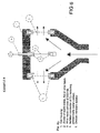
- the electrolytic cell may be placed into a pipe conducting the water to be treated according to the invention, for example as shown i figure 5.
- the process water flowing through the unit (the openings 18) of the wire mesh of the unit obtains a close reactive contact with the oxidants and radicals formed on the anode threads of the wire mesh.
- the drawing figures 4A and 4B are expanded views (rectangular and circular versions) of the four layers 20, 12, 14, 16 of which each unit is structured.
- Fig. 4B shows the anode or cathode wire mesh where the conductor frame of a superior rigid conductive material is supporting the exposed anode or cathode surface in order to obtain an even current distribution over a large area or in case of high current.
- the mesh is attached to the conductor frame at both sides.
- the non-conductive spacing material in the same shape as the rigid conductor frame and attached to one of the meshes at one side.
- the assembly of a single anode or cathode can be stacked in numbers from one anode and one cathode up to 50 altogether.
- Anode and cathode might be of identical material or different. In case of similar material DC power applied might be alternated to avoid scaling and uneven tear and wear.
- Anode size might each be more than 1 m diameter.
- Flow capacity might be from a few litres /hr in the smallest cells to more than 1000 m3/hr in each of the largest cell.
- Typical current density at 316L anodes is 38 mA/cm2 provided Cl content at 5 ppm. For noble metals the above have been tested to 270 Amp at a anode area of 0,5 cm2.
- the wire-mesh may be formed of individual wires mounted parallel to one another to the frame, or of individual wires that are woven, knitted or plaited or induction-welded to form the aforementioned mesh.
- each individual wire or the perforated foil is attached to the conducting frame such that electrical contact is achieved for even current distribution over exposed electrode area and exposed electrode area becomes tension stabilised to eliminate use of conventional spacer, whereupon frame or conductor is isolated from the liquid electrolyte by an oxidant-resistant isolator/coating.
- liquid After the liquid has processed according to the invention it is directed through an hydrophobic adsorption filter or hydrophobic adsorption media in order to remove potential excess organic compounds.
- the liquid is preferably directed through a flotation device in order to remove electro flotated organic material.
- the exposed gap between anode and cathode have no need for conventional or further spacers, as spacing is provided by applying a foil, membrane or coarse of non conductive material of the same shape as the frame itself.
- the clearance might be as low as 0,3 mm. This implies that by the invention, it is possible to obtain a high current density with a very low voltage, something which involve that the Law of Farraday easily is exceeded without flow or current loss due to spacer and a desired production of reactive oxidants is provided.
- wire/mesh or perforated foil at both sides of the conductor frame is that it allows mm2 uppscaling for extreme currents passing to the exposed area for electrolysis.
- a 5mm thick frame covered at both sides allows placement of a thin spacing frame at both sides where the cathode mesh/perforated foil can be placed close to the anode in a distance down to 0,3 mm. With varying distances more than 3000 Amps can be passed through an electrode.
- the present invention differs from existing electrolytic cells/processes in that one by means of a very low voltage, may obtain the necessary high current density of large area without this reducing the volume through flow of the liquid to be handled. This also implies that large volumes of liquid to be handled may be treated very cheaply.
- the volume capacity of the electrolytic cell is not changed in contrast to other electrolytic cells even though the distance between the anode and cathode is reduced from i.e. 5 cm to 0,3 mm in that the same volume-liquid flow goes through the anode and cathode independent of the mutual distance between them.
- the present invention differs from the existing anodes in that the use of wires to a considerable degree increases the area of the anode compared to the weight of the metal and the real surface. Thus, the costs of the precious metals are also reduced considerably at the same time as the efficiency per cm 2 , is increased.
- the present invention differs from existing electrolytic cells/processes in that it is possible to obtain high current density, a low consumption of energy and a high through flow by volume of liquid, as the distance between the anode and cathode can be reduced to 0,3 mm without this reducing the capacity of the electrolytic cell, so that it may be used with the ion conductivity in fresh water (surface water and ground water).
- an anode mesh of tantalum including some wires of another precious metal from the platinum group produces mainly ozone, radicals and hydrogen peroxide, and very little hypo chlorite and chloride dioxide. This is due to the fact that all flow of current will take place from the precious metal wires such as tantalum immediately will immediately obtain an isolating layer of oxide.
- the present invention differs from existing electrolytic cells/processes in that it can be used with a low cost for treating large volumes of liquid, such as surface water, fresh water and ground water with the composition existing in great parts of the world today. Even with both anode and cathode of 316 L steel or higher alloyed metal without the anode oxidising or corroding. This is due to a high electrode surface with very low consumption of energy is producing the necessary oxidant (ozone and radicals) even with the average conductivity in ground water and surface fresh water.
- the present invention is characterised in that liquid may be conducted through anode and cathode in that a frame of conductive material is fixed to the anode and cathode mesh with sufficient contact, the mesh is preferably conducted at both sides of the frame, and the conductor frame is coated with a non oxidizable material in order to protect against contact with electrolyte.
- the spacing material in a non-conductive oxidant resistant material may be provided whereafter the anode or cathode mesh is assembled.
- the spacing material is of identical shape as the conductor frame and of varying thickness.
- the structure shown in fig. 5 was used in control and verified experiments for treating the ballast water from ships and including sea water containing bacteria, micro organism, algae and spores.
- the water including a high degree of pollution was conducted through the cell once, as shown by arrows, with an amperage of 100 A.
- the result show that 100% of the abovementioned pollutants, including spores, where destroyed.
- An extrapolation of the results based on the experiments show that the required consumption of energy will be 5kWh in order to handle 2500 m3/h process water with an anode surface of 2,5 m 2 .
- Fig. 6 shows a section of an electrolytic cell there foil or wire mesh to which a liquid was added to both the plain surfaces whereupon the liquid is conducted through the cathode on each side of the anode so that hydrogen does not come in contact with the anode or in the field between the anode and cathode.
- This electrolytic cell was used for destruction of poly aromatic hydrocarbons (PAH) and PCB on particles in a sea water slurry. With a careful addition of electrolyte and circulation of the mixture during 20 minutes, the PAH-content was reduced by 99,6% and the PCB-content was reduced by 76% based on relatively high concentrations.
- PAH poly aromatic hydrocarbons
- PCB-content was reduced by 76% based on relatively high concentrations.
- An electrode stack as described in Figure 4B comprising 5 anodes and 6 cathodes all of 316 L steel and a total anode area of 1013 cm2 were assembled with a 1 mm spacer as described in fig. 4.
- the liquid flow through the cell was at a rate of 10 1/min.
- Effluent was untreated drinking water from a surface source with salinity varying between 1,5 and 5 ppm, and with high humic content.
- E-coli bacteria were added to the water at a concentration of 560.000 bacterias/ml. Passed once through the cell with current 20 Amp showed a total disinfection effetness in all samples taken after treathment. That is sample series taken between 2 and 20 minutes after passed trough the cell.
- Drill cuttings from oil and gas industry was processed through an electrode under conditions as described in EXAMPLE 4. The cuttings was disperged into 221 of effluent containing 6 % NaCl. Scope was to remove Hydrocarbons from particles. Initial content of 7,62% total Hydrocarbon vas reduced to 1.32 % in an hour processing.
- Deep blue textile dying wastewater was passed through an anode of noble metal threads stretched across a 5 inch diameter sircular anode conductor frame so that the area of anode only was 0,5 cm2 total.
- the 2 cathodes was wire mesh of 316L steel. 20 l was batch proccesed with flow 180 l/min through the electrode. Volume 20 l. NaCl oontent 5%. Current was 270 Amp. In 25 to 35 seconds the waste water became blank.
Abstract
Description
- The present invention relates to a structure of an electrode for use as an anode/cathode in an electrolytic cell as stated in the preamble of the following
patent claim 1. - Further the invention relates to a method for preparing said electrode structure.
- The invention also relates to a use of the electrolytic cell including anode and cathode as mentioned above.
- The invention relates to the technology concerning the production of oxidants and radicals which are used to oxidising and eliminating organic material in liquids, and organic materials on particles in liquids, and for destruction of bacteria, spores, micro organisms, algae and virus.
- Today anodes (electrodes) are produced by the use of electrolytic coating a substrate with thin layers of precious (noble) metals. However these electrodes have a particularly short lifetime and they do not tolerate being exposed to high voltages over time. If they are exposed to high voltages they will burn. During the process a dissolving/precipitation occurs from the anode so that it is corroded.
- There is also a production of anodes of pure metals or alloys of such metals, and which do not belong to the precious metal group, but these are quickly corroded in use, they do not produce the desired oxidant, nor can they be exposed to the desired voltage.
- Another lesser-known method in use today involves that tantalum, iridium, or a mixture of these are rolled down to between 0,015 and 0,035 mm and is welded to a core for an anode which is made of titanium, aluminium or copper. By this method a frictional welding is used. The lifetime for these electrodes is longer than of the electrodes that are made by use of electrolysis. They tolerate substantially higher voltage and current. With these advantages in variables for electrolyses process, i.e. voltages from 0-380V and currents from 0-1000 Amperes, a mixture of oxidants is produced including a very high reactivity, power and possibility for functional balancing of the single oxidants (Cl2, ClO3 -, O3, O2, H2O2, OH, ClOH, O), exceeding the effect of, and reduces the undesirable effect of oxidants from anodes produced by other methods.
- The limitations for the preparation by these methods are the variation span in the mixture of alloys. For example it is known that platinum/iridium-alloys (Pt/Ir) including more than 20% iridium is difficult to roll down to the desired thickness. Today it is known that the alloy can be rolled down to 33 micron (0,033mm). Higher concentrations of Ir leads to even greater problems, and the prepared foil often becomes brittle. It is also desireable that the foil have a high degree of hardness in order to increase the mechanical resistance to wear and tear. Further the thickness of the foil is decisive in determining how much of certain oxidants is produced in a certain liquid with a given voltage and current. It is further known that for example pure platinum technically may only be rolled down to 15 micron (0.015mm). Below this thickness it is not possible to obtain a dense foil (without pores).
- Recently methods for vacuum/plasma spraying of tantalum and precious metals according to the abovementioned method have extended the potential of use in that methods for spraying of thinner layers have been developed, and at the same time increased the variation span of the mixture of an alloy with 100% pore density, and thus the specific area of use has been extended.
- The known electrolytic processes in its simplest form provide Cl2 as an oxidation agent. Further oxidants (ClO3 -, O3, O2, H2O2, OH, ClOH, O) are however far more chemically reactive, and are provided by coating a substrate with precious metals where a voltage is exposed in a range where the law of Farraday is exceeded.
- Of these components the radicals are in particular the most powerful oxidation agents, both with regard to power and non-desirable side-effects (halogenated compounds of organic material). The problem of the known electrolytic processes is that the radicals cannot be utilised since they have a lifetime of a thousandth of a second and are therefore only present very close to the surface of the anode. As only a very small part of the liquid amount that is conducted through an electrolytic cell makes contact with this anodic surface, large amounts of liquids cannot effectively be exposed to radical exposure for reaction with organic compounds, bacteria, virus etc, which is desired to be eliminated from the liquid.
- Known electrolytic processes form hydrogen at the cathode. Hydrogen lowers considerably the formation of oxidants by the anode since the hydrogen forms water when it comes in contact with the oxidant. This applies in particular to OH-radicals in contact with hydrogen. The hydrogen gas also reduces the conductivity of the liquid when it is present in the voltage field between the anode and cathode, and in contact with the anode.
- It is known from US patent 6,328,875 that electrolytic cell designs have been developed with anodes /cathodes made of conductive porous elements consisting of metal, including noble metals, or carbon from welded or woven wire cloth, expanded metal or carbon felt, carbon woven cloth or reticulated vitreous carbon and metallic foam. The structure includes an open solution where the effluent is passed in-between a spacer/anode and cathode to open area (open solution). The stack is clamped together and anode/cathode are separated, mono polar or bipolar, by spacer to prevent shortcut. The effluent is then passed in parallel with the anode/cathode/spacer in the process.
- Furthermore it is known that US patent 6,342,151 comprises anodes/cathodes made of permeable conductive material selected from the group consisting of perforated plates, screens, wool, felt and weave made of stainless steel, aluminium, copper, platinized titanium, mixed metal oxides, gold and gold plated steel. Also this electrode use spacers to prevent shortcut between anode and cathode when distance between said components are small.
- It is well known that spacers increases current consumption in an electrolytic process and reduces flow capacity through the electrode.
- It is also well known that fouling due to scaling caused by Mg and Ca content in the effluent treated is a substantial problem with respect to electrolysis. The scaling problem occurs when velocity of Mg and Ca contained effluent (such as sea water) is passed through an anode/cathode reaction. If the velocity of the effluent is too slow, a bridge of crystals will accelerating be built between anode and cathode causing fouling of the process. Increasing the velocity in such extent might prevent this in such extent that all Mg and Ca build up are transported away before it attaches to the cathode. Another way, provided that anode and cathode are of same or equal reactive material, is to alternate the polarity of the anode and the cathode regularly. Then scaling burst off the cathode as it is reverted to anode.
- It is an object of invention to provide a new and improved construction of the electrode that eliminates energy losses due to need of spacer and still allows close distance between anode and cathode without risk of shortcut.
- It is an object of the invention to allow large flow vertical through the electrode while maintaining full effectiveness of the electrolysis in order to prevent fouling due to scaling.
- It is an object of the invention to provide a new and improved construction of an electrode to be used to prepare oxidants as mentioned above, for example Cl2, ClO3 -, O3, O2, H2O2, (OH), (ClOH), (O), and which optimally can utilise the radical production at the surface of the anode.
- Further it is an object of invention to provide a new an improved construction of an electrode where a reduced oxidation effect due to hydrogen interference between anode and cathode, and on the cathode, may be eliminated.
- It is further an object of invention to bring substantially all liquid in contact with an area close to the anode where the radicals are produced, and where radicals have a lifetime of some thousands of second (milliseconds). As the radicals are the predominant oxidation agent, also with regard to non-desirable side effects of further oxidation agents, it is essential for inventiveness, compared with the state of art technology, that the radical effects on the materials to be disinfected/oxidised, are considerably increased.
- It is also an object of the invention to prepare an anode wherein the consumption of energy is considerably reduced when it is connected to a circuit according to the invention in relation to the volume of liquid to be handled.
- It is also an object of invention to provide a new and improved method in which it is possible to simply prepare an electrode with a higher performance in use than the previously known electrodes.
- Further it is an object of the invention to provide a use of the electrode.
- The device, the method and the use according to the invention are characterised by the features appearing in the characteristic clauses of the independent claims.
- The further features of the invention are given in the dependent claims, respectively.
- According to the present invention a method is provided which is suitable in using wire, knitted, woven or plaited wire mesh net of metals for use for, and production of an anode and/or a cathode which may be used to produce a mixture of oxidants, and in particular radicals by use of electrolysis.
- The invention is characterised in that an anode is assembled with wires or wire mesh, knitted or plaited of tantalum, niobium, hafnium, zirconium, platinum, rhodium, iridium, ruthenium, palladium, or an alloy thereof, or a mixture of different wires of the abovementioned metal.
- The invention is characterised in that the cathode is assembled with wires or a wire mesh, knitted or plaited of 316L steelwires, or higher alloyed conductive and resistant material.
- Further the invention is characterised in that the wires or anode meshs and cathode meshs may be joined close together without short circuit contact in that a separation mesh, membrane or coarse crossed squared mesh in a non-conductive oxidant resistant material, which is arranged between the anode and cathode in order to separate these to prevent a short circuit contact.
- According to a preferred embodiment of the invention, a superior conductive material may be arranged on the anode and cathode, individually or in a coarse square pattern, and may be thereafter insulated by means of oxidant durable insulating material from electrolyte in order to provide an even current through flow over the exposed wire mesh or wire net area.
- The invention is characterised in that anode/cathode is arranged in a flow of liquid which has to pass through the anode/cathode, or that the anode/cathode is arranged in a vessel for production of oxidant.
- Further, the invention is characterised in that by electrolysing of freshwater one is able to use both cathode mesh and anode mesh in SS316L quality or higher alloyed metal.
- Further, the invention is characterised in that by electrolysis of freshwater a woven, knitted or plaited mesh may be replaced with a plate in SS316L which is perforated by means of photochemistry in order to substitute a wire mesh.
- By exposing electrical current with high current density exceeding the law of Faraday to a wire assembly or a woven, knitted or plaited mesh of the metal or a precious metal as disclosed above, one achieves a high production of radicals and reactive oxidants. This production implies a particularly high effect by oxidising of organic material and disinfection.
- The present invention differs from existing electrolytic cells/processes where the effect of radicals, ozone, hydrogen peroxide, chlordioxide, and hypochlorite is prepared from anodes with a layer of precious metals which produces the reactive oxidants, and by providing an electrode structure whereby the production of radicals may be utilised more optimally than previously.
- This may be provided by the anode having a shape including a mesh of metal as disclosed, having a wire distance of from 100 micron to 25000 micron or a square opening of from 18 micron to 25000 micron where the metal is exposed to voltages exceeding the law of Farraday resulting in a high production of oxidant close to the anode.
- By using the electrode structure according to the invention the liquid to be handled is brought to pass a wire net mesh where the opening in the wire mesh has an opening size of minimum 15 micron (15 µm). On passing the radical reaction with a lifetime of some thousandth of a second, will act substantially on all the liquid flowing through the wire mesh. Other electrolytic oxidation processes obtain 1-3% radical effect on the surface of the anode. With the present invention one obtains an efficiency of 95-98% utilisation of the radical effect. This is due to the fact that up to 95-98% of the liquid is passing close to the anode where the radicals spend their lifetime in that the liquid in fact flows through the fine-meshed anode.
- The present invention differs from the existing electrolytic cells/processes in that the anode and the cathode may be conducted very close together by means of a separation element (spacer) or a separation wire mesh, prepared by a coarse squared non-conducting material.
- According to a prefered embodiment of the invention, it is prefered that each frame is covered by two layers of wire mesh, on layer of each plane side of the frame. It is however sufficient that the frame includes only one wire mesh layer, as shown in figure 1A, 1B and 1C.
- According to the most prefered embodiment, a wire mesh or parallel threads, 12 and 14, respectively is bounded to each side of the
conductor frame 10 by exposing it to a substantial tension force/pressure and possibly by applying heat and using a bonding agent, or by induction welding or laser welding simoultaneously with that wire or perforated foil is kept under sufficient tension. Thus the wires or mesh covering the exposed area on each plane side of the conductor are stabilized. Possibly the wire mesh includes parallel threads where each tenth or twentieth thread is of tantalum while the others are platinum threads. - Onto one of wire layers 14 of the
frame 10 or said separation wire mesh, a spacer foil 16 (of a PVS or polypropylene material) of a non-conducting material, and having the exact shape (plane view) of theframe 10, is positioned and anchored. Thus theopenings 18 of theseparation wire mesh 16 are aligned with the throughflow openings 18 of theframe 10. Thus the throughflow openings 18 of theframe 10 which are "covered" by thewire mesh spacer foil 16. The thickness of theframe 10 may be 5 mm, while thespacer foil 16 may have a thickness as low as 0,3 mm (representing the separation between the anode and cathode surfaces). Thus the water/liquid through flow properties of the frame in use, is not obstructed. - Thus an electrode unit, for an anode or cathode, includes said conductive frame having a number of through
flow openings 18, both plane sides of which being covered with the perforated plate, the wires (parallel threads or a wire mesh), and thespacer foil 18 on one side only. Further the conductive frame (for a cathode or anode) 10 includesmeans 20 for connecting to adequate current supply (voltage and current). - In order to construct a single (the simplest) electrolytic cell, two electrode units as shown in figure 4 are mounted mutually close to each other in alignment, so that said
spacer layer 18, provides for the necessary distance (for example of 0,3 mm) between theanode surface 14 of one electrode unit and thecathode surface 12 of the adjacent electrode unit. - It is prefered to cover the conductor frame (as being of stainless steel) 10 and the sections of the conductive wire (wire mesh) 12,14 covering said frame, with a non oxidizable material in order to protect against contact with the electrolyte, in a similar manner as shown in figure 1C.
- An electrolytic cell consisting of a number of the abovementioned pairs of electrode units (up to 50 pairs), may have a circular, or rectanuglar shape. A circular electrode unit may for example have a diameter of up to 1 meter, representing the water through flow of the unit. The electrolytic cell may be placed into a pipe conducting the water to be treated according to the invention, for example as shown i figure 5. When applying a sufficient voltage to the anode/cathode sets, the process water flowing through the unit (the openings 18) of the wire mesh of the unit, obtains a close reactive contact with the oxidants and radicals formed on the anode threads of the wire mesh.
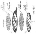
- The drawing figures 4A and 4B are expanded views (rectangular and circular versions) of the four
layers - Fig. 4B shows the anode or cathode wire mesh where the conductor frame of a superior rigid conductive material is supporting the exposed anode or cathode surface in order to obtain an even current distribution over a large area or in case of high current. The mesh is attached to the conductor frame at both sides. The non-conductive spacing material in the same shape as the rigid conductor frame and attached to one of the meshes at one side.
- The assembly of a single anode or cathode can be stacked in numbers from one anode and one cathode up to 50 altogether.
- Anode and cathode might be of identical material or different. In case of similar material DC power applied might be alternated to avoid scaling and uneven tear and wear. Anode size might each be more than 1 m diameter. Flow capacity might be from a few litres /hr in the smallest cells to more than 1000 m3/hr in each of the largest cell. Typical current density at 316L anodes is 38 mA/cm2 provided Cl content at 5 ppm. For noble metals the above have been tested to 270 Amp at a anode area of 0,5 cm2.
- The wire-mesh may be formed of individual wires mounted parallel to one another to the frame, or of individual wires that are woven, knitted or plaited or induction-welded to form the aforementioned mesh.
- Preferably each individual wire or the perforated foil is attached to the conducting frame such that electrical contact is achieved for even current distribution over exposed electrode area and exposed electrode area becomes tension stabilised to eliminate use of conventional spacer, whereupon frame or conductor is isolated from the liquid electrolyte by an oxidant-resistant isolator/coating.
- It is prefered to direct the water to be processed through a mechanical particle extractor in order to remove all particles and organisms larger than the light aperture in the electrode.
- Further, after the liquid has processed according to the invention it is directed through an hydrophobic adsorption filter or hydrophobic adsorption media in order to remove potential excess organic compounds.
- After the treatment, the liquid is preferably directed through a flotation device in order to remove electro flotated organic material.
- The exposed gap between anode and cathode have no need for conventional or further spacers, as spacing is provided by applying a foil, membrane or coarse of non conductive material of the same shape as the frame itself. The clearance might be as low as 0,3 mm. This implies that by the invention, it is possible to obtain a high current density with a very low voltage, something which involve that the Law of Farraday easily is exceeded without flow or current loss due to spacer and a desired production of reactive oxidants is provided.
- Another advantage by applying wire/mesh or perforated foil at both sides of the conductor frame is that it allows mm2 uppscaling for extreme currents passing to the exposed area for electrolysis. A 5mm thick frame covered at both sides allows placement of a thin spacing frame at both sides where the cathode mesh/perforated foil can be placed close to the anode in a distance down to 0,3 mm. With varying distances more than 3000 Amps can be passed through an electrode.
- The present invention differs from existing electrolytic cells/processes in that one by means of a very low voltage, may obtain the necessary high current density of large area without this reducing the volume through flow of the liquid to be handled. This also implies that large volumes of liquid to be handled may be treated very cheaply. The volume capacity of the electrolytic cell is not changed in contrast to other electrolytic cells even though the distance between the anode and cathode is reduced from i.e. 5 cm to 0,3 mm in that the same volume-liquid flow goes through the anode and cathode independent of the mutual distance between them.
- The present invention differs from the existing anodes in that the use of wires to a considerable degree increases the area of the anode compared to the weight of the metal and the real surface. Thus, the costs of the precious metals are also reduced considerably at the same time as the efficiency per cm2, is increased.
- The present invention differs from existing electrolytic cells/processes in that it is possible to obtain high current density, a low consumption of energy and a high through flow by volume of liquid, as the distance between the anode and cathode can be reduced to 0,3 mm without this reducing the capacity of the electrolytic cell, so that it may be used with the ion conductivity in fresh water (surface water and ground water).
- With the present invention it is possible to combine the effect of different metals. For example, an anode mesh of tantalum including some wires of another precious metal from the platinum group, produces mainly ozone, radicals and hydrogen peroxide, and very little hypo chlorite and chloride dioxide. This is due to the fact that all flow of current will take place from the precious metal wires such as tantalum immediately will immediately obtain an isolating layer of oxide.
- The present invention differs from existing electrolytic cells/processes in that it can be used with a low cost for treating large volumes of liquid, such as surface water, fresh water and ground water with the composition existing in great parts of the world today. Even with both anode and cathode of 316 L steel or higher alloyed metal without the anode oxidising or corroding. This is due to a high electrode surface with very low consumption of energy is producing the necessary oxidant (ozone and radicals) even with the average conductivity in ground water and surface fresh water.
- The present invention is characterised in that liquid may be conducted through anode and cathode in that a frame of conductive material is fixed to the anode and cathode mesh with sufficient contact, the mesh is preferably conducted at both sides of the frame, and the conductor frame is coated with a non oxidizable material in order to protect against contact with electrolyte. The spacing material in a non-conductive oxidant resistant material may be provided whereafter the anode or cathode mesh is assembled. The spacing material is of identical shape as the conductor frame and of varying thickness.
- The device according to the invention will be explained more in detail with reference to the following specification and the following drawings, wherein:
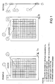
- Fig. 1A shows a schematic plan view of an
anode 1 of a high conductivity Cu (copper)frame 1 covered with a single wire mesh of a noble metal. - Fig. 1B shows a
cathode frame 3 including a woven, knitted or plaited wire mesh 4 (for example of stainless steel 316L). Thesuperior conductor frame 1 to which the wire mesh is fixed, is isolated with a molded oxidant-resistand isolator. - Figure 1C shows the side section of the oxidant-resistand isolator by
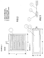
reference numeral 5, in addition to the other details of the. - Fig. 2 shows an anode of wires which are fixed to a superior conductor which is isolated.
- Fig. 3 shows an anode of a foil which is fixed to a superior conductor which is isolated.
- Fig. 4A shows an expanded view of a rectangular electrode structure, and which is disclosed previously in this specification.
- Fig. 4B shows an expanded view of a circular electrode structure according to the invention.
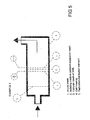
- Fig. 5 shows a section of an electrolytic cell (with only one set of an anode and cathode shown for simplicity) made of a wire, plaited, woven or knitted mesh with a separation mesh between the anode and cathode in order to prevent a short circuit contact. The liquid is processed in that it is conducted through the anode and cathode so that hydrogen is conducted out from the cathode and away from the anode.
- The structure shown in fig. 5 was used in control and verified experiments for treating the ballast water from ships and including sea water containing bacteria, micro organism, algae and spores. The water including a high degree of pollution, was conducted through the cell once, as shown by arrows, with an amperage of 100 A. The result show that 100% of the abovementioned pollutants, including spores, where destroyed. An extrapolation of the results based on the experiments show that the required consumption of energy will be 5kWh in order to handle 2500 m3/h process water with an anode surface of 2,5 m2.
- Similarly the structure as shown in fig. 5 was used to prove oxidant production in fresh water. With an anode/cathode-distance of 1mm and an anode of a precious metal mesh produced 0,5 ppm ozone during one through flow. Up scaling models show that 2500 m3/h require 87 kWh with an anode surface of 2,5 m2.
- The experiment was repeated with an anode mesh and cathode mesh of 316 L steel. During one through flow 0,91 ppm ozone was produced in the drinking water with 80 V and 3 A.
- Fig. 6 shows a section of an electrolytic cell there foil or wire mesh to which a liquid was added to both the plain surfaces whereupon the liquid is conducted through the cathode on each side of the anode so that hydrogen does not come in contact with the anode or in the field between the anode and cathode.
- This electrolytic cell was used for destruction of poly aromatic hydrocarbons (PAH) and PCB on particles in a sea water slurry. With a careful addition of electrolyte and circulation of the mixture during 20 minutes, the PAH-content was reduced by 99,6% and the PCB-content was reduced by 76% based on relatively high concentrations.
- Some further examples of the invention are now presented.
- An electrode stack as described in Figure 4B comprising 5 anodes and 6 cathodes all of 316 L steel and a total anode area of 1013 cm2 were assembled with a 1 mm spacer as described in fig. 4. The liquid flow through the cell was at a rate of 10 1/min. Effluent was untreated drinking water from a surface source with salinity varying between 1,5 and 5 ppm, and with high humic content. E-coli bacteria were added to the water at a concentration of 560.000 bacterias/ml. Passed once through the cell with current 20 Amp showed a total disinfection efectivness in all samples taken after treathment. That is sample series taken between 2 and 20 minutes after passed trough the cell.
- The same samples were analysed for trihalomethanes (Clororganic and bromoorganic compounds). These samples showed results in the range of 0.9 - 2,5 ppb. This is extremely low compared to clorination of water. Total count of bacteria was more than 10
log 3 by applying 18,5 Amp. - The same setup and similar water as in EXAMPLE 1 where used but the number of electrodes was multiplied to achieve higher amperage. The scope was to inactivate IPN Virus. Desired 10 log3 inactivation was achieved at 60 Amp. Furthermore Areomonas Salmonicida was also inactivated with the same log at same conditions. Total restoxidant varied from 0.7 to 1.6 ppm.
- Produced water from oil and gas production containing PAH, Hydrocarbons, Phenols and BETEX with significant concentration was passed through 1 noble metal anode of knitted wire cloth and 2 cathodes as shown in fig. 4B. Amperage was 300 Amp and anode area 180 cm2. The flow rate was 180 1/min. Phenols were reduced from 1580 microgram/l to 0.51 microgram /1.
PAH 16 was reduced from 34,7 microgram/l to 3,92 microgram/l.
NPD was reduced from 114 microgram/l to 3.92 microgram/l
TEOM (C10 - C40) was reduced from 16 mg/l to 2,41 mg/l - A contaminated fluid from a oil refinery containing 1600 ppm H2S, 2-3 % Phenols and 2900 ppm Ammonium was processed through two noble metal wire mesh anodes stacked with 3 cathodes of 316 L steel mesh. Anode aerea total was 225 cm2. Current was 300 Amp. Flow 140 l/min. Cl-content was 2% NaCl. After batch proccesing a volume of 40 l for 15 minutes the H2S was oxidized to 0 ppm and further 15 minutes processing resulted in ammonium content of 3 ppm and Phenol content of 300 ppb. During processing pH was controlled by additives.
- 250 g Drill cuttings from oil and gas industry was processed through an electrode under conditions as described in EXAMPLE 4. The cuttings was disperged into 221 of effluent containing 6 % NaCl. Scope was to remove Hydrocarbons from particles. Initial content of 7,62% total Hydrocarbon vas reduced to 1.32 % in an hour processing.
- Deep blue textile dying wastewater was passed through an anode of noble metal threads stretched across a 5 inch diameter sircular anode conductor frame so that the area of anode only was 0,5 cm2 total. The 2 cathodes was wire mesh of 316L steel. 20 l was batch proccesed with flow 180 l/min through the electrode. Volume 20 l. NaCl oontent 5%. Current was 270 Amp. In 25 to 35 seconds the waste water became blank.
Claims (25)
- Structure of an electrode of electrically conducting material for use as an anode and/or a cathode in an electrolytic cell, and comprising a spacer means to prevent electrical contact between electrodes when used, and being arranged for through flow conducting of a process liquid, such as water, to be treated, characterised by,
a conductive frame (10) having a number of liquid through flow openings (18) and including means (20) for connection to a current supply,
one or both plane sides of the frame (10) is covered with a conductive perforated foil or a wire mesh (12,14), and
the spacer means (16) is a perforated foil or wire mesh being adapted to cover one of the plane surfaces of the perforated foil or a wire mesh (12,14), and the plane section of said spacer foil corresponds mainly to the plane section of the frame (10). - Structure of an electrode according to claim 1, characterised in that the wire mesh or wire mesh net (12,14) includes parallel threads were each tenth or twentieth threads is of tantalum while the intermediate threads are of platinum.
- Structure according to claims 1-3, characterised in that the wires of the wire mesh (12,14) are individually from 100 microns to 25000 microns apart, and when they are woven, knitted, induction-welded or plaited into mesh, have an air aperture of from 15 microns to 25000 microns.
- Structure according to any of preceding claims, characterised in that each wire has a diameter in a range of 0.010 mm to 5 mm.
- Structure according to any of preceding claims, characterised in that the foil or a wire mesh (12,14) is formed of tantalum, niobium, hafnium, zirconium, platinum, rhodium, iridium, ruthenium, palladium or any alloy of these, or of an alloy or an composition of wires of the different aforementioned metals.
- Structure according to any of preceding claims, characterised in that the foil electrode (12,14) consists of a plate in SS316L or higher alloy metal which is closely perforated by photochemistry.
- Structure according to any of preceding claims, characterised in that the through-flow openings (18) of the spacer means (16) are aligned with the through flow openings (18) of the frame (10).
- Structure according to any of preceding claims, characterised in that the spacer foil (16) is a PVC or polypropylene sheet and is welded to the frame (10).
- Structure according to any of preceding claims, characterised in that the thickness of the frame (10) is about 5 mm.
- Structure of electrode according to any of preceding claims, characterised in that the frame (20) is covered with a non oxidizable material in order to protect against contact with the mentioned process liquid.
- Structure according to any of preceding claims, characterised in that the foil thickness is from 25-1000 microns and diameter of each perforation from 25-2000 microns.
- Method for preparing an electrode according to claim 1, characterised in that perforated foil or wire mesh sheets (12,14,16) are anchored to the frame (10) by subjecting the perforated foil or wire mesh sheets to a stretch or tension force, and then being forced against and fixed to the frame surface by means of a welding and/or adhesive operation.
- Method according to claim 12, characterised in that the perforated foil or wire mesh sheets (12,14,16) are anchored to the frame (10) by friction welding, laser welding or preferably by use of pressure/heat and bonding and exposing the foil or wire mesh to said sufficient tension force.
- Use of the electrode structure according to claims 1-11, in an electrolytic cell where single electrodes according to said claims are stacked and interconnected to form anode/cathode pairs in numbers from one and up to 50 altogether inside a pipe, for processing of liquids/water being conducted through the electrode-pairs of the cell in the pipe, in that a current is applied to each pair of anode and cathode.
- Use of electrode structure according to claim 14 in an electrolytic cell processing liquids/water where the anode and cathode is of identical material or different, and in case of similar material, a direct current DC power applied might be alternated to avoid scaling and uneven tear and wear.
- Use of electrode structure according to any of claims 14-15 in an electrolytic cell processing liquids/water in that the flow capacity might be from a few litres/hour and up to more than 1000 m3/hour.
- Use of electrode structure according to claims 14-16 in an electrolytic cell processing liquids/water in that a typical current density at 316L anodes is 38 mA/cm2 provided a Cl content at 5 ppm, and for noble metals the current is 270 Amp at an anode area of 0,5 cm2, and the distance between the anode surface of one electrode unit and the cathode surface of the neighbouring electrode unit may be about 0,3 mm.
- Use of anode and cathode according to the preceding claims 14-17, in an electrolytic cell, for production of oxidants trough electrolysis, for oxidation of organic material in liquids, and organic material on particles in liquids.
- Use of anode and cathode according to the preceding claims 14-18, in an electrolytic cell, for production of oxidants trough electrolysis, for oxidation and destruction of bacteria, spores, micro-organisms, algae and virus in liquids.
- Use of anode and cathode according to the preceding claims 14-19, in an electrolytic cell, for production of oxidants trough electrolysis, for treatment of fresh water and drinking water.
- Use of anode and cathode according to the preceding claims 14-20, in an electrolytic cell, in which polluted liquid/water is conducted through the through flow openings (18) of anode and cathode of the cell.
- Use of anode and cathode according to the preceding claims 14-21, in an electrolytic cell, for production of oxidants trough electrolysis, for destruction of virus, spores and bacteria, and micro organisms, algae and algal cysts smaller than 100 microns in ballast water from ships.
- Use of anode and cathode according to the preceding claims 14-22, where the liquid that is being treated, before it is treated according to the invention, is directed trough a mechanical particle extractor in order to remove all particles and organisms larger than light aperture in the electrode.
- Use of the anode and cathode according to the preceding claims 14-23, where the liquid that has been treated, after it is treated according to the invention, is directed trough an hydrophobic adsorption filter or hydrophobic adsorption media in order to remove potential excess organic compounds.
- Use of the anode and cathode according to the preceding claims 14-24, where the liquid while treated is directed trough a flotation device in order to remove electro floated organic material.
Applications Claiming Priority (3)
| Application Number | Priority Date | Filing Date | Title |
|---|---|---|---|
| NO20024054 | 2002-08-26 | ||
| NO20024054A NO321256B1 (en) | 2002-08-26 | 2002-08-26 | Electrode designs and their use |
| PCT/NO2003/000296 WO2004018733A2 (en) | 2002-08-26 | 2003-08-26 | Structure of an electrode for use in an electrolytic cell |
Publications (2)
| Publication Number | Publication Date |
|---|---|
| EP1540041A2 EP1540041A2 (en) | 2005-06-15 |
| EP1540041B1 true EP1540041B1 (en) | 2006-06-14 |
Family
ID=19913935
Family Applications (1)
| Application Number | Title | Priority Date | Filing Date |
|---|---|---|---|
| EP03792900A Expired - Lifetime EP1540041B1 (en) | 2002-08-26 | 2003-08-26 | Structure of an electrode for use in an electrolytic cell |
Country Status (17)
| Country | Link |
|---|---|
| US (1) | US7611611B2 (en) |
| EP (1) | EP1540041B1 (en) |
| JP (1) | JP2005536639A (en) |
| KR (1) | KR20050057009A (en) |
| CN (1) | CN100537849C (en) |
| AT (1) | ATE330044T1 (en) |
| AU (1) | AU2003263684A1 (en) |
| BR (1) | BR0313935A (en) |
| CA (1) | CA2536815A1 (en) |
| DE (1) | DE60306172T2 (en) |
| DK (1) | DK1540041T3 (en) |
| EA (1) | EA010551B1 (en) |
| ES (1) | ES2266900T3 (en) |
| MX (1) | MXPA05002211A (en) |
| NO (1) | NO321256B1 (en) |
| PL (1) | PL374540A1 (en) |
| WO (1) | WO2004018733A2 (en) |
Families Citing this family (40)
| Publication number | Priority date | Publication date | Assignee | Title |
|---|---|---|---|---|
| CN1197786C (en) * | 2003-06-13 | 2005-04-20 | 大连海事大学 | Method for killing living beings in the course of transmission of ballast water by using ship and its equipment |
| KR100597254B1 (en) * | 2005-09-14 | 2006-07-06 | 한국해양연구원 | Sterilizing apparatus for ship ballast water using electrolysis |
| KR100843404B1 (en) * | 2007-01-23 | 2008-07-03 | 삼성전기주식회사 | Hydrogen generator having a porous electrode plate |
| KR100810718B1 (en) * | 2007-05-23 | 2008-03-07 | (주)대성그린테크 | Wastewater treatment method using electrolysis for water reuse |
| JP5680417B2 (en) * | 2007-11-16 | 2015-03-04 | アクゾ ノーベル ナムローゼ フェンノートシャップAkzo Nobel N.V. | Method for producing alkali metal chlorate |
| JP5011084B2 (en) * | 2007-12-18 | 2012-08-29 | 有限会社スプリング | Device for killing microorganisms in water and method for killing microorganisms in water |
| DE102009013380A1 (en) | 2009-03-09 | 2010-09-16 | Hansgrohe Ag | Process for the decomposition of partially fluorinated and perfluorinated surfactants |
| MD244Z (en) * | 2009-09-04 | 2011-02-28 | Государственный Университет Молд0 | Electrode for electrolytic production of hydrogen and process for manufacturing thereof |
| CN101786748B (en) * | 2010-03-30 | 2012-06-13 | 青岛海德威科技有限公司 | Efficient inactivation and energy-saving ship ballast water process method and system |
| DE102010021424A1 (en) | 2010-05-26 | 2011-12-01 | Gerald Metge | Metallic gauze anode useful in a galvanic cell, comprises a tube made of metal thread, fabric or knitted fabric |
| NZ590016A (en) * | 2010-12-17 | 2013-06-28 | Waikatolink Ltd | An electrolytic cell comprising at least two electrodes and at least one insulating layer with perforations |
| ITMI20111938A1 (en) * | 2011-10-26 | 2013-04-27 | Industrie De Nora Spa | ANODIC COMPARTMENT FOR CELLS FOR ELECTROLYTIC EXTRACTION OF METALS |
| CN102424457B (en) * | 2011-10-27 | 2013-06-12 | 湖南万容科技股份有限公司 | Treating system for industrial wastewater containing heavy metal and treating method thereof |
| DK2812464T3 (en) * | 2012-02-10 | 2019-11-18 | Hydrox Holdings Ltd | METHOD AND APPARATUS FOR GAS PRODUCTION |
| CN102583662B (en) * | 2012-02-24 | 2013-07-31 | 浙江工业大学 | Screen plunger piston flow electrolyzing device and method for treating organic wastewater |
| CN103723798B (en) * | 2012-10-12 | 2016-02-10 | 格伦特克有限公司 | Water Exit portion is in the sterilized water production cartridge of side |
| CN102965689A (en) * | 2012-11-19 | 2013-03-13 | 扬州中电制氢设备有限公司 | Ultrathin polar plate electrolytic cell |
| US9788772B2 (en) | 2013-01-31 | 2017-10-17 | KHN Solutions, Inc. | Wearable system and method for monitoring intoxication |
| US8878669B2 (en) | 2013-01-31 | 2014-11-04 | KHN Solutions, Inc. | Method and system for monitoring intoxication |
| EP2772469A1 (en) | 2013-02-27 | 2014-09-03 | Bayer Technology Services GmbH | Micro-lamellae electrode cells and their use |
| US9250228B2 (en) | 2014-01-22 | 2016-02-02 | KHN Solutions, Inc. | Method and system for remotely monitoring intoxication |
| EP2913306A1 (en) | 2014-02-27 | 2015-09-02 | Bayer Technology Services GmbH | Process for cleaning pesticide remnants from field spray devices |
| JP5687789B1 (en) * | 2014-03-19 | 2015-03-18 | 優章 荒井 | Electrolyzed water generator |
| RU2712545C2 (en) * | 2014-10-27 | 2020-01-29 | Индустрие Де Нора С.П.А. | Electrode for electrochlorination processes and method for production thereof |
| US9777382B2 (en) | 2015-06-03 | 2017-10-03 | Kabushiki Kaisha Toshiba | Electrochemical cell, oxygen reduction device using the cell and refrigerator using the oxygen reduction device |
| EP3378640A4 (en) * | 2015-11-20 | 2019-07-17 | Lintec of America, Inc. | Sheet, heating element, and heating device |
| CN106734156A (en) * | 2015-11-23 | 2017-05-31 | 章日行 | The system that cadmium and lead-contaminated soil are renovated with Electrodynamic force method |
| JP6853048B2 (en) * | 2017-01-18 | 2021-03-31 | 株式会社日本トリム | Electrolyzed water generator and dialysate preparation water production equipment |
| CN107244733B (en) * | 2017-05-11 | 2020-03-24 | 中国科学院生态环境研究中心 | Accelerating device for sewage and wastewater synergistic treatment |
| US11324449B2 (en) | 2018-03-22 | 2022-05-10 | KHN Solutions, Inc. | Method and system for transdermal alcohol monitoring |
| US11006895B2 (en) | 2018-03-22 | 2021-05-18 | KHN Solutions, Inc. | Method and system for transdermal alcohol monitoring |
| KR102017567B1 (en) * | 2018-11-27 | 2019-09-03 | 주식회사 웨스코일렉트로드 | An anode for electrolysis |
| CN114008247A (en) * | 2019-12-19 | 2022-02-01 | 株式会社Lg化学 | Electrode for electrolysis |
| JPWO2021153406A1 (en) | 2020-01-27 | 2021-08-05 | ||
| NO347082B1 (en) * | 2020-04-24 | 2023-05-08 | Dennis Mason | A micro-organisms treatment device and a method for mechanical treatment of micro-organisms |
| CN113941450A (en) * | 2020-07-16 | 2022-01-18 | 北京石墨烯研究院有限公司 | Micro-nano particle size grading device and method |
| US11602306B2 (en) | 2021-01-12 | 2023-03-14 | KHN Solutions, Inc. | Method and system for remote transdermal alcohol monitoring |
| EP4039655A1 (en) * | 2021-02-05 | 2022-08-10 | Université Gustave Eiffel | Reactor allowing the continuous filtering of a fluid flowing through a filter and with an on-site electrochemical regeneration of the filter |
| CN115074769B (en) * | 2022-05-06 | 2023-07-04 | 同济大学 | Large-area electrode support body structure of alkaline water electrolysis tank |
| DE102022209312A1 (en) | 2022-09-07 | 2024-03-07 | Siemens Energy Global GmbH & Co. KG | Process for producing a composite of expanded mesh, stack of expanded mesh and gantry machine |
Family Cites Families (20)
| Publication number | Priority date | Publication date | Assignee | Title |
|---|---|---|---|---|
| JPS5421641U (en) * | 1977-07-15 | 1979-02-13 | ||
| US4345986A (en) * | 1980-06-02 | 1982-08-24 | Ppg Industries, Inc. | Cathode element for solid polymer electrolyte |
| SU986505A1 (en) * | 1981-07-13 | 1983-01-07 | Ленинградский Ордена Трудового Красного Знамени Инженерно-Строительный Институт | Flotation apparatus |
| JPS58217683A (en) * | 1982-06-09 | 1983-12-17 | Showa Denko Kk | Electrolytic cell |
| EP0322478A1 (en) * | 1987-12-30 | 1989-07-05 | Kay Wilms | Method and apparatus for the treatment of water by anodic oxidation, especially for the production of sterile drinking water |
| US4911993A (en) * | 1988-02-01 | 1990-03-27 | Eltech Systems Corporation | Bipolar, filter-press, consumable metal anode battery |
| AT390274B (en) * | 1988-03-15 | 1990-04-10 | Steininger Karl Heinz | ELECTRODE |
| JP3212318B2 (en) * | 1990-02-15 | 2001-09-25 | 旭硝子株式会社 | Monopolar ion exchange membrane electrolytic cell |
| RU2036719C1 (en) * | 1991-03-19 | 1995-06-09 | Институт химии нефти СО РАН | Adsorbent for cleaning surface of water and soil from oil and oil products |
| JPH05329483A (en) * | 1991-04-15 | 1993-12-14 | Konica Corp | Treatment of water to be treated and bipolar electrolytic cell used therefor |
| US5322597A (en) | 1992-07-30 | 1994-06-21 | Minnesota Mining And Manufacturing Company | Bipolar flow cell and process for electrochemical fluorination |
| RU2047569C1 (en) * | 1992-10-01 | 1995-11-10 | Товарищество с ограниченной ответственностью Фирма "Искра" | Method for clarifying and disinfecting stock farm waste water |
| JP3383334B2 (en) * | 1992-12-16 | 2003-03-04 | クロリンエンジニアズ株式会社 | How to recycle sulfuric acid |
| JP3360365B2 (en) * | 1993-07-29 | 2002-12-24 | クロリンエンジニアズ株式会社 | Method for regenerating tetraalkylammonium hydroxide |
| ITMI940853A1 (en) * | 1994-05-03 | 1995-11-03 | Nora Permelec S P A Ora De Nora S P A De | ELECTROLIZERS FOR THE PRODUCTION OF SODIUM HYPOCHLORITE AND SODIUM CHLORATE EQUIPPED WITH IMPROVED ELECTRODES |
| JPH11128938A (en) * | 1997-10-29 | 1999-05-18 | Honda Motor Co Ltd | Formation of electrolyzed water |
| US6315886B1 (en) * | 1998-12-07 | 2001-11-13 | The Electrosynthesis Company, Inc. | Electrolytic apparatus and methods for purification of aqueous solutions |
| US6274009B1 (en) * | 1999-09-03 | 2001-08-14 | International Dioxide Inc. | Generator for generating chlorine dioxide under vacuum eduction in a single pass |
| CA2385847C (en) * | 1999-09-27 | 2009-01-06 | Shinko Pantec Co., Ltd. | Electrode plate for water electrolysis device, electrode plate unit, solid electrolyte membrane unit, and electrochemical cell |
| DE10063195A1 (en) * | 2000-12-19 | 2002-06-20 | Basf Ag | Electrolysis cell, useful for production of organic and inorganic products, has electrochemically active counter electrode area that is smaller than that of working electrode |
-
2002
- 2002-08-26 NO NO20024054A patent/NO321256B1/en not_active IP Right Cessation
-
2003
- 2003-08-26 DK DK03792900T patent/DK1540041T3/en active
- 2003-08-26 MX MXPA05002211A patent/MXPA05002211A/en active IP Right Grant
- 2003-08-26 KR KR1020057003385A patent/KR20050057009A/en not_active Application Discontinuation
- 2003-08-26 EP EP03792900A patent/EP1540041B1/en not_active Expired - Lifetime
- 2003-08-26 ES ES03792900T patent/ES2266900T3/en not_active Expired - Lifetime
- 2003-08-26 DE DE60306172T patent/DE60306172T2/en not_active Expired - Lifetime
- 2003-08-26 AT AT03792900T patent/ATE330044T1/en not_active IP Right Cessation
- 2003-08-26 AU AU2003263684A patent/AU2003263684A1/en not_active Abandoned
- 2003-08-26 BR BR0313935-2A patent/BR0313935A/en not_active IP Right Cessation
- 2003-08-26 CA CA002536815A patent/CA2536815A1/en not_active Abandoned
- 2003-08-26 EA EA200500409A patent/EA010551B1/en not_active IP Right Cessation
- 2003-08-26 PL PL03374540A patent/PL374540A1/en unknown
- 2003-08-26 JP JP2004530682A patent/JP2005536639A/en not_active Ceased
- 2003-08-26 CN CNB038234696A patent/CN100537849C/en not_active Expired - Fee Related
- 2003-08-26 US US10/526,032 patent/US7611611B2/en not_active Expired - Fee Related
- 2003-08-26 WO PCT/NO2003/000296 patent/WO2004018733A2/en active IP Right Grant
Also Published As
| Publication number | Publication date |
|---|---|
| WO2004018733A2 (en) | 2004-03-04 |
| JP2005536639A (en) | 2005-12-02 |
| CN100537849C (en) | 2009-09-09 |
| DK1540041T3 (en) | 2006-10-16 |
| PL374540A1 (en) | 2005-10-31 |
| NO20024054D0 (en) | 2002-08-26 |
| EA010551B1 (en) | 2008-10-30 |
| NO321256B1 (en) | 2006-04-10 |
| DE60306172D1 (en) | 2006-07-27 |
| MXPA05002211A (en) | 2005-10-18 |
| WO2004018733A3 (en) | 2005-02-24 |
| CN1714175A (en) | 2005-12-28 |
| CA2536815A1 (en) | 2004-03-04 |
| AU2003263684A8 (en) | 2004-03-11 |
| KR20050057009A (en) | 2005-06-16 |
| EA200500409A1 (en) | 2005-12-29 |
| AU2003263684A1 (en) | 2004-03-11 |
| US7611611B2 (en) | 2009-11-03 |
| EP1540041A2 (en) | 2005-06-15 |
| US20060144709A1 (en) | 2006-07-06 |
| ES2266900T3 (en) | 2007-03-01 |
| ATE330044T1 (en) | 2006-07-15 |
| BR0313935A (en) | 2005-07-12 |
| DE60306172T2 (en) | 2007-06-06 |
Similar Documents
| Publication | Publication Date | Title |
|---|---|---|
| EP1540041B1 (en) | Structure of an electrode for use in an electrolytic cell | |
| KR100432971B1 (en) | Electrolytic Apparatus, Methods for Purification of Aqueous Solutions and Synthesis of Chemicals | |
| JP2005536639A5 (en) | ||
| JP2002531704A (en) | Electrolytic apparatus, method for purifying aqueous solution, and method for synthesizing chemical substance | |
| CA2835727A1 (en) | Efficient treatment of wastewater using electrochemical cell | |
| EP0711731B1 (en) | Ozone water production apparatus | |
| GB2515324A (en) | Electrolytic advance oxidation processes to treat wastewater, brackish and saline water without hydrogen evolution | |
| CA2545764C (en) | Electrolytic cell for treating contaminated water | |
| US8080150B2 (en) | Electrolytic cell | |
| KR101148145B1 (en) | Device for sterilization and removal of microorganism underwater | |
| RU2322394C1 (en) | Device for processing drinking water | |
| US20220250942A1 (en) | Reactor allowing the continuous filtration of liquid flowing through a filter with in situ electrochemical regeneration of the filter | |
| AU2675699A (en) | Electrolytic cell with porous membranes to concentrate anions | |
| CA2891040A1 (en) | Direct contact cell | |
| JPH08134678A (en) | Ozonized water producing device | |
| EP2089326A1 (en) | Treatment system of ships ballast water, offshore petroleum platforms and vessels, in general, through a process in an electrochemical reactor | |
| WO2003027029A1 (en) | Method and apparatus for the destruction of dyes and other organic molecules | |
| KR20110078158A (en) | Effective electrolysis method of seawater | |
| Elgün et al. | Evaluation of Ti/Pt Anode Efficiency and Energy Consumption in Turbidity and Suspended Solids Removal from Paper Industry Wastewater: The Effect of pH and Support Electrolyte Type | |
| WO2015137878A1 (en) | Filter devices and filtering methods | |
| GB2367072A (en) | Mineraliser reaction cell for purifying liquids |
Legal Events
| Date | Code | Title | Description |
|---|---|---|---|
| PUAI | Public reference made under article 153(3) epc to a published international application that has entered the european phase |
Free format text: ORIGINAL CODE: 0009012 |
|
| 17P | Request for examination filed |
Effective date: 20050325 |
|
| AK | Designated contracting states |
Kind code of ref document: A2 Designated state(s): AT BE BG CH CY CZ DE DK EE ES FI FR GB GR HU IE IT LI LU MC NL PT RO SE SI SK TR |
|
| AX | Request for extension of the european patent |
Extension state: AL LT LV MK |
|
| GRAP | Despatch of communication of intention to grant a patent |
Free format text: ORIGINAL CODE: EPIDOSNIGR1 |
|
| GRAS | Grant fee paid |
Free format text: ORIGINAL CODE: EPIDOSNIGR3 |
|
| GRAA | (expected) grant |
Free format text: ORIGINAL CODE: 0009210 |
|
| AK | Designated contracting states |
Kind code of ref document: B1 Designated state(s): AT BE BG CH CY CZ DE DK EE ES FI FR GB GR HU IE IT LI LU MC NL PT RO SE SI SK TR |
|
| AX | Request for extension of the european patent |
Extension state: AL LT LV MK |
|
| PG25 | Lapsed in a contracting state [announced via postgrant information from national office to epo] |
Ref country code: IT Free format text: LAPSE BECAUSE OF FAILURE TO SUBMIT A TRANSLATION OF THE DESCRIPTION OR TO PAY THE FEE WITHIN THE PRESCRIBED TIME-LIMIT;WARNING: LAPSES OF ITALIAN PATENTS WITH EFFECTIVE DATE BEFORE 2007 MAY HAVE OCCURRED AT ANY TIME BEFORE 2007. THE CORRECT EFFECTIVE DATE MAY BE DIFFERENT FROM THE ONE RECORDED. Effective date: 20060614 Ref country code: CZ Free format text: LAPSE BECAUSE OF FAILURE TO SUBMIT A TRANSLATION OF THE DESCRIPTION OR TO PAY THE FEE WITHIN THE PRESCRIBED TIME-LIMIT Effective date: 20060614 Ref country code: SI Free format text: LAPSE BECAUSE OF FAILURE TO SUBMIT A TRANSLATION OF THE DESCRIPTION OR TO PAY THE FEE WITHIN THE PRESCRIBED TIME-LIMIT Effective date: 20060614 Ref country code: CH Free format text: LAPSE BECAUSE OF FAILURE TO SUBMIT A TRANSLATION OF THE DESCRIPTION OR TO PAY THE FEE WITHIN THE PRESCRIBED TIME-LIMIT Effective date: 20060614 Ref country code: AT Free format text: LAPSE BECAUSE OF FAILURE TO SUBMIT A TRANSLATION OF THE DESCRIPTION OR TO PAY THE FEE WITHIN THE PRESCRIBED TIME-LIMIT Effective date: 20060614 Ref country code: SK Free format text: LAPSE BECAUSE OF FAILURE TO SUBMIT A TRANSLATION OF THE DESCRIPTION OR TO PAY THE FEE WITHIN THE PRESCRIBED TIME-LIMIT Effective date: 20060614 Ref country code: FI Free format text: LAPSE BECAUSE OF FAILURE TO SUBMIT A TRANSLATION OF THE DESCRIPTION OR TO PAY THE FEE WITHIN THE PRESCRIBED TIME-LIMIT Effective date: 20060614 Ref country code: LI Free format text: LAPSE BECAUSE OF FAILURE TO SUBMIT A TRANSLATION OF THE DESCRIPTION OR TO PAY THE FEE WITHIN THE PRESCRIBED TIME-LIMIT Effective date: 20060614 |
|
| REG | Reference to a national code |
Ref country code: GB Ref legal event code: FG4D |
|
| REG | Reference to a national code |
Ref country code: CH Ref legal event code: EP |
|
| REG | Reference to a national code |
Ref country code: IE Ref legal event code: FG4D |
|
| REF | Corresponds to: |
Ref document number: 60306172 Country of ref document: DE Date of ref document: 20060727 Kind code of ref document: P |
|
| PG25 | Lapsed in a contracting state [announced via postgrant information from national office to epo] |
Ref country code: IE Free format text: LAPSE BECAUSE OF NON-PAYMENT OF DUE FEES Effective date: 20060828 |
|
| PG25 | Lapsed in a contracting state [announced via postgrant information from national office to epo] |
Ref country code: MC Free format text: LAPSE BECAUSE OF NON-PAYMENT OF DUE FEES Effective date: 20060831 |
|
| PG25 | Lapsed in a contracting state [announced via postgrant information from national office to epo] |
Ref country code: SE Free format text: LAPSE BECAUSE OF FAILURE TO SUBMIT A TRANSLATION OF THE DESCRIPTION OR TO PAY THE FEE WITHIN THE PRESCRIBED TIME-LIMIT Effective date: 20060914 |
|
| REG | Reference to a national code |
Ref country code: RO Ref legal event code: EPE |
|
| REG | Reference to a national code |
Ref country code: DK Ref legal event code: T3 |
|
| REG | Reference to a national code |
Ref country code: GR Ref legal event code: EP Ref document number: 20060403222 Country of ref document: GR |
|
| PG25 | Lapsed in a contracting state [announced via postgrant information from national office to epo] |
Ref country code: PT Free format text: LAPSE BECAUSE OF FAILURE TO SUBMIT A TRANSLATION OF THE DESCRIPTION OR TO PAY THE FEE WITHIN THE PRESCRIBED TIME-LIMIT Effective date: 20061114 |
|
| LTIE | Lt: invalidation of european patent or patent extension |
Effective date: 20060614 |
|
| REG | Reference to a national code |
Ref country code: HU Ref legal event code: AG4A Ref document number: E000757 Country of ref document: HU |
|
| REG | Reference to a national code |
Ref country code: CH Ref legal event code: PL |
|
| ET | Fr: translation filed | ||
| REG | Reference to a national code |
Ref country code: ES Ref legal event code: FG2A Ref document number: 2266900 Country of ref document: ES Kind code of ref document: T3 |
|
| PLBE | No opposition filed within time limit |
Free format text: ORIGINAL CODE: 0009261 |
|
| STAA | Information on the status of an ep patent application or granted ep patent |
Free format text: STATUS: NO OPPOSITION FILED WITHIN TIME LIMIT |
|
| 26N | No opposition filed |
Effective date: 20070315 |
|
| PG25 | Lapsed in a contracting state [announced via postgrant information from national office to epo] |
Ref country code: BG Free format text: LAPSE BECAUSE OF FAILURE TO SUBMIT A TRANSLATION OF THE DESCRIPTION OR TO PAY THE FEE WITHIN THE PRESCRIBED TIME-LIMIT Effective date: 20060914 Ref country code: EE Free format text: LAPSE BECAUSE OF FAILURE TO SUBMIT A TRANSLATION OF THE DESCRIPTION OR TO PAY THE FEE WITHIN THE PRESCRIBED TIME-LIMIT Effective date: 20060614 |
|
| PG25 | Lapsed in a contracting state [announced via postgrant information from national office to epo] |
Ref country code: LU Free format text: LAPSE BECAUSE OF NON-PAYMENT OF DUE FEES Effective date: 20060826 Ref country code: TR Free format text: LAPSE BECAUSE OF FAILURE TO SUBMIT A TRANSLATION OF THE DESCRIPTION OR TO PAY THE FEE WITHIN THE PRESCRIBED TIME-LIMIT Effective date: 20060614 |
|
| PGFP | Annual fee paid to national office [announced via postgrant information from national office to epo] |
Ref country code: NL Payment date: 20080731 Year of fee payment: 6 |
|
| PG25 | Lapsed in a contracting state [announced via postgrant information from national office to epo] |
Ref country code: CY Free format text: LAPSE BECAUSE OF FAILURE TO SUBMIT A TRANSLATION OF THE DESCRIPTION OR TO PAY THE FEE WITHIN THE PRESCRIBED TIME-LIMIT Effective date: 20060614 |
|
| PGFP | Annual fee paid to national office [announced via postgrant information from national office to epo] |
Ref country code: BE Payment date: 20080723 Year of fee payment: 6 Ref country code: HU Payment date: 20080729 Year of fee payment: 6 |
|
| PGFP | Annual fee paid to national office [announced via postgrant information from national office to epo] |
Ref country code: RO Payment date: 20090528 Year of fee payment: 7 |
|
| BERE | Be: lapsed |
Owner name: *ORO A/S Effective date: 20090831 |
|
| REG | Reference to a national code |
Ref country code: NL Ref legal event code: V1 Effective date: 20100301 |
|
| PG25 | Lapsed in a contracting state [announced via postgrant information from national office to epo] |
Ref country code: BE Free format text: LAPSE BECAUSE OF NON-PAYMENT OF DUE FEES Effective date: 20090831 |
|
| PG25 | Lapsed in a contracting state [announced via postgrant information from national office to epo] |
Ref country code: NL Free format text: LAPSE BECAUSE OF NON-PAYMENT OF DUE FEES Effective date: 20100301 Ref country code: HU Free format text: LAPSE BECAUSE OF NON-PAYMENT OF DUE FEES Effective date: 20090827 |
|
| PGFP | Annual fee paid to national office [announced via postgrant information from national office to epo] |
Ref country code: FR Payment date: 20100609 Year of fee payment: 8 |
|
| PGFP | Annual fee paid to national office [announced via postgrant information from national office to epo] |
Ref country code: GR Payment date: 20100527 Year of fee payment: 8 |
|
| PG25 | Lapsed in a contracting state [announced via postgrant information from national office to epo] |
Ref country code: RO Free format text: LAPSE BECAUSE OF NON-PAYMENT OF DUE FEES Effective date: 20100826 |
|
| PGFP | Annual fee paid to national office [announced via postgrant information from national office to epo] |
Ref country code: ES Payment date: 20100930 Year of fee payment: 8 |
|
| PGFP | Annual fee paid to national office [announced via postgrant information from national office to epo] |
Ref country code: DK Payment date: 20110830 Year of fee payment: 9 |
|
| REG | Reference to a national code |
Ref country code: GR Ref legal event code: ML Ref document number: 20060403222 Country of ref document: GR Effective date: 20120302 |
|
| REG | Reference to a national code |
Ref country code: FR Ref legal event code: ST Effective date: 20120430 |
|
| PG25 | Lapsed in a contracting state [announced via postgrant information from national office to epo] |
Ref country code: GR Free format text: LAPSE BECAUSE OF NON-PAYMENT OF DUE FEES Effective date: 20120302 |
|
| PG25 | Lapsed in a contracting state [announced via postgrant information from national office to epo] |
Ref country code: FR Free format text: LAPSE BECAUSE OF NON-PAYMENT OF DUE FEES Effective date: 20110831 |
|
| REG | Reference to a national code |
Ref country code: ES Ref legal event code: FD2A Effective date: 20121207 |
|
| PG25 | Lapsed in a contracting state [announced via postgrant information from national office to epo] |
Ref country code: ES Free format text: LAPSE BECAUSE OF NON-PAYMENT OF DUE FEES Effective date: 20110827 |
|
| REG | Reference to a national code |
Ref country code: DK Ref legal event code: EBP Effective date: 20130831 |
|
| PG25 | Lapsed in a contracting state [announced via postgrant information from national office to epo] |
Ref country code: DK Free format text: LAPSE BECAUSE OF NON-PAYMENT OF DUE FEES Effective date: 20130831 |
|
| PGFP | Annual fee paid to national office [announced via postgrant information from national office to epo] |
Ref country code: GB Payment date: 20140824 Year of fee payment: 12 |
|
| GBPC | Gb: european patent ceased through non-payment of renewal fee |
Effective date: 20150826 |
|
| PG25 | Lapsed in a contracting state [announced via postgrant information from national office to epo] |
Ref country code: GB Free format text: LAPSE BECAUSE OF NON-PAYMENT OF DUE FEES Effective date: 20150826 |
|
| PGFP | Annual fee paid to national office [announced via postgrant information from national office to epo] |
Ref country code: DE Payment date: 20160826 Year of fee payment: 14 |
|
| REG | Reference to a national code |
Ref country code: DE Ref legal event code: R119 Ref document number: 60306172 Country of ref document: DE |
|
| PG25 | Lapsed in a contracting state [announced via postgrant information from national office to epo] |
Ref country code: DE Free format text: LAPSE BECAUSE OF NON-PAYMENT OF DUE FEES Effective date: 20180301 |