EP1539588B1 - Vorrichtung und verfahren zur herstellung von rohrenförmigen etiketten aus wärmeschrumpfbarer folie und zum einsetzen von behältern darin - Google Patents
Vorrichtung und verfahren zur herstellung von rohrenförmigen etiketten aus wärmeschrumpfbarer folie und zum einsetzen von behältern darin Download PDFInfo
- Publication number
- EP1539588B1 EP1539588B1 EP03790918A EP03790918A EP1539588B1 EP 1539588 B1 EP1539588 B1 EP 1539588B1 EP 03790918 A EP03790918 A EP 03790918A EP 03790918 A EP03790918 A EP 03790918A EP 1539588 B1 EP1539588 B1 EP 1539588B1
- Authority
- EP
- European Patent Office
- Prior art keywords
- tubular
- label
- plate
- precut
- labels
- Prior art date
- Legal status (The legal status is an assumption and is not a legal conclusion. Google has not performed a legal analysis and makes no representation as to the accuracy of the status listed.)
- Expired - Lifetime
Links
- 238000000034 method Methods 0.000 title claims abstract description 15
- 229920006257 Heat-shrinkable film Polymers 0.000 title claims abstract description 8
- 238000002372 labelling Methods 0.000 claims abstract description 6
- 238000004804 winding Methods 0.000 claims abstract description 5
- 238000007789 sealing Methods 0.000 claims description 15
- 238000010438 heat treatment Methods 0.000 claims description 4
- 239000000853 adhesive Substances 0.000 claims description 2
- 230000001070 adhesive effect Effects 0.000 claims description 2
- 238000007664 blowing Methods 0.000 claims description 2
- 230000007246 mechanism Effects 0.000 claims description 2
- 230000002093 peripheral effect Effects 0.000 claims 1
- 230000000452 restraining effect Effects 0.000 claims 1
- 108700002783 roundabout Proteins 0.000 description 15
- 241001411320 Eriogonum inflatum Species 0.000 description 1
- 239000003831 antifriction material Substances 0.000 description 1
- 230000015572 biosynthetic process Effects 0.000 description 1
- 230000000903 blocking effect Effects 0.000 description 1
- 238000007599 discharging Methods 0.000 description 1
- 238000003780 insertion Methods 0.000 description 1
- 230000037431 insertion Effects 0.000 description 1
- 238000004519 manufacturing process Methods 0.000 description 1
- 239000000126 substance Substances 0.000 description 1
- 230000001360 synchronised effect Effects 0.000 description 1
- 230000001131 transforming effect Effects 0.000 description 1
Images


Classifications
-
- B—PERFORMING OPERATIONS; TRANSPORTING
- B65—CONVEYING; PACKING; STORING; HANDLING THIN OR FILAMENTARY MATERIAL
- B65C—LABELLING OR TAGGING MACHINES, APPARATUS, OR PROCESSES
- B65C3/00—Labelling other than flat surfaces
- B65C3/06—Affixing labels to short rigid containers
- B65C3/065—Affixing labels to short rigid containers by placing tubular labels around the container
-
- Y—GENERAL TAGGING OF NEW TECHNOLOGICAL DEVELOPMENTS; GENERAL TAGGING OF CROSS-SECTIONAL TECHNOLOGIES SPANNING OVER SEVERAL SECTIONS OF THE IPC; TECHNICAL SUBJECTS COVERED BY FORMER USPC CROSS-REFERENCE ART COLLECTIONS [XRACs] AND DIGESTS
- Y10—TECHNICAL SUBJECTS COVERED BY FORMER USPC
- Y10T—TECHNICAL SUBJECTS COVERED BY FORMER US CLASSIFICATION
- Y10T156/00—Adhesive bonding and miscellaneous chemical manufacture
- Y10T156/10—Methods of surface bonding and/or assembly therefor
- Y10T156/1002—Methods of surface bonding and/or assembly therefor with permanent bending or reshaping or surface deformation of self sustaining lamina
- Y10T156/1036—Bending of one piece blank and joining edges to form article
- Y10T156/1038—Hollow cylinder article
-
- Y—GENERAL TAGGING OF NEW TECHNOLOGICAL DEVELOPMENTS; GENERAL TAGGING OF CROSS-SECTIONAL TECHNOLOGIES SPANNING OVER SEVERAL SECTIONS OF THE IPC; TECHNICAL SUBJECTS COVERED BY FORMER USPC CROSS-REFERENCE ART COLLECTIONS [XRACs] AND DIGESTS
- Y10—TECHNICAL SUBJECTS COVERED BY FORMER USPC
- Y10T—TECHNICAL SUBJECTS COVERED BY FORMER US CLASSIFICATION
- Y10T156/00—Adhesive bonding and miscellaneous chemical manufacture
- Y10T156/17—Surface bonding means and/or assemblymeans with work feeding or handling means
- Y10T156/1702—For plural parts or plural areas of single part
- Y10T156/1744—Means bringing discrete articles into assembled relationship
- Y10T156/1768—Means simultaneously conveying plural articles from a single source and serially presenting them to an assembly station
- Y10T156/1771—Turret or rotary drum-type conveyor
Definitions
- the object of the present invention is a process for forming tubular labels made of heat shrinkable film according to the preamble of claim 1, and a machine for forming labels and inserting bottles or containers into the formed labels according to the preamble of claim 5.
- the object of the present invention consists of transforming a rotating roundabout labelling machine in a labelling machine for tubular labels by forming a label from a precut label made of a reeled film in order to obtain the tubular label receiving the bottle.
- US-A-4 286 421 is a process for forming tubular labels disclosed according to the preamble of claim 1.
- the cost of a tubular label is the same as the cost of a flat label cut from a reel;
- 1 is a disk rotating around a vertical axis 2, said disk is known as roundabout.
- a plurality of small round plates 3 are mounted on the roundabout which in turn can rotate around their own vertical axis as it will be described later.
- drum 5 is a drum for transferring precut labels, said drum, also known per se, is provided with negative pressure areas for adherently keep a precut label before transferring it on a round plate 3.
- Containers or bottles 6 are transported on the round plate by a star-shaped inlet conveyor 7 rotating according to arrow 8 in a direction opposite to the rotation of the roundabout.
- 9 is a star-shaped conveyor for discharging the labelled containers, which conveyor will introduce said containers in a known heating tunnel (not shown) for heat shrinking each tubular label to adhere it on the outer surface of the corresponding container.
- the heating tunnel can be substituted with a heat shrinking roundabout mechanically connected to the star-shaped discharge conveyor 9.
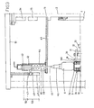
- each round plate 3 consists of an upper support surface 3a for supporting each container 6; a tubular element 3b descends from surface 3a, whose inner chamber 3c communicates with the outer surface by a plurality of evenly distributed holes 10.
- the container support round plate has therefore a tubular shape, whose side surface is completely perforated so that a negative or positive pressure can be established on the surface of a tubular label 100 as will be better explained with reference to the operation of the machine.
- the tubular round plate is supported by a shaft 11, a recess 12 defined in the top of shaft communicates via holes 13 with a chamber 14 defined by an outer jacket 15.
- Diameter of chamber 14 is substantially the same as the outer diameter of the tubular round plate so that it can receive the latter when alternatively moves up and down.
- the shaft 11 abuts via a shim 16 made of antifriction material on an annular cam 17 supported by a surface 18 integral with the machine frame.
- Outer jacket 15 is integrally supported by the disk or roundabout 1 coupled to shaft 19 driven by known means of which a gear wheel 20 is shown.
- a stationary mounting 21 fixed to surface 18 supports said shaft 19 by thrust bearings 22.
- An stationary air dispenser 23 fixed to the mounting 21 supplies air to a rotating dispenser 23a supported by the roundabout 1.
- the stationary dispenser 23 is supplied by a duct 24 connected to a vacuum pump and a duct 25 connected to a blowing fan (not shown); the rotating dispenser 23a supplies, into a duct 26, chamber 14 which in turn supplies holes 10 with air at a negative or positive pressure depending on the location of the rotating dispenser.
- a cycloidal cam 27 rotates the tubular round plate around its own vertical axis.
- Cycloidal cam rotates also a gear wheel 28 meshing a gear wheel 29 coupled to a portion 11a of shaft 11.
- a grooved portion 11a is provided on shaft 11 so that the latter can simultaneously translate and rotate around its vertical axis.
- the cycloidal cam rotates the tubular round plate in order to move the label at a constant speed from the transfer drum to the tubular round plate and stop the latter for several seconds in order to seal the overlapped ends of the label in a predetermined position.
- a sealing device is fixed to each round plate which comprises a bar heat sealing device 30 supported by horizontal sliding guides 31 carried by plate 32 integral with roundabout 1.
- An air piston 33 moves the bar heat sealing device 30 from a rest position to a contact position in which the precut label ends are overlapped to form a tubular label.
- a bell-shaped element 40 located upon the support surface 3a is coaxial with the tubular round plate 3, which element aligns bottle 6 on the round plate with the rotating axis of the latter during the rotation of the roundabout from the star-shaped inlet conveyor to the star-shaped discharge conveyor.
- the bell-shaped element 40 is freely supported by a rod 41 whose end is fixed to a piston 42 slidingly received in a cylinder 43 which in turn slides in a jacket 44.
- Jacket 44 is supported by a surface 45 integral with the rotating shaft 19 of the roundabout and defines a slot 46 from which projects a pin 47 whose first end is integral with the cylinder 43 and the second end supports a roller 48 adapted to engage a cam 49 by an elastic bias of a spring 50 inserted in said jacket 44.
- Cam 49 is supported by a top surface 51 integral with the fixed frame of the machine and is contoured in order to move the bell-shaped element 40 along a first downward stroke 52 so that it can grip the bottle by its stopper and along a second downward stroke 53 to insert the bottle into the tubular label formed around the tubular round plate.
- cam 17 is contoured as cam 49 in the portion regarding the slope of the tubular round plate.
- Cam 17 is therefore a means for moving downwardly the tubular round plate by a stroke which allows to transfer the bottle into the tubular label.
- the top of cylinder 43 can be supplied with compressed air for moving the respective piston and rod 41 carrying the bell-shaped element in order to compensate the height difference of bottles with respect to an height of a sample bottle.
- Surface 45 can change its vertical position with respect to the roundabout 1, according to known methods, for locating the machine according to the varying heights of different bottles.
- a bottle is put on the round plate 3 by the star-shaped inlet conveyor, at the same time the bell-shaped element 40 comes down on the bottle stopper blocking firmly the bottle on surface 3a while allowing its rotation.
- the tubular label (known as sleeve) is formed by winding it on the tubular round plate 3 which it is now at a negative pressure so that the label adheres firmly on the outer surface of the tubular portion of the round plate.
- the round plate 3 is rotated by cinematic mechanisms connected to the cycloidal cam 27 in order to transfer the label at a constant speed.
- the drum 5 rotation phase is different from that of the roundabout 1 rotation; due to that feature, in order to keep the constant speed condition, the transfer is carried out for a very small angle in comparison to a phase condition, so that the time necessary to seal the tubular label ends will take advantage of that.
- the heat sealing device 30 seals in few seconds the overlapped ends forming the finished tubular label.
- the heat sealing bar will withdraw from the label and pressurized air will be introduced in chamber 3c and consequently air will be blown into holes 10 keeping the tubular label detached from the round plate in order to allow the bottle-plate assembly to descend from the risen position to the position wherein the surface 3a is flush with the jacket 15 by the conjugated operation of cams 17 and 49.
- This position coincides with the bottle discharge position and the bell-shaped element 40 will be risen so that the star-shaped discharge conveyor discharges the bottle which will be subjected to a heat treatment to adhere the heat shrinkable label to the bottle.
- the tubular round plate After the bottle discharge, the tubular round plate will be risen by cam 17 to the higher position in order to receive a new bottle starting again a new cycle.
- a plurality of round plates are located on the roundabout with respective heat sealing bars, centering bell-shaped elements; obviously on the round plates every operative step will be performed while the roundabout rotates.
- Each heat sealing system is independently operated by one electrical valve synchronized in order to ensure the correct sealing according to the varying angular speed of the roundabout.
- the machine process is essentially based on the fact the precut label is wound on a tubular round plate carrying a bottle to be labelled; then the vertical overlapped ends of the precut label are heat sealed in a predetermined position forming a tubular label.
- the label is peeled off the tubular round plate by pressurized air jets, afterwards said bottle with its round plate can translate downwards for entering the label once the overlapped vertical ends are heat sealed. Then the label will be heated to adhere to the bottle.
- the abovementioned machine can be easily modified to handle different bottle shapes or label size by substituting the cycloidal cam ensuring the constant speed during the transfer of the precut label from the drum 5 to the tubular round plate and substituting the tubular round plate and the associated disk 3d depending on the bottle diameter.
- the label ends have been bonded by heat sealing, however they can be bonded with other methods, such as chemical sealing, o more generally by adhesives.
Landscapes
- Labeling Devices (AREA)
- Packages (AREA)
- Containers And Plastic Fillers For Packaging (AREA)
- Lining Or Joining Of Plastics Or The Like (AREA)
Claims (9)
- Verfahren zum Ausbilden von schlauchförmigen Etiketten aus Schrumpffolie und Anbringen derselben an Flaschen oder Behältern, indem die Flaschen oder Behälter in die ausgebildeten schlauchförmigen Etiketten überführt werden, dadurch gekennzeichnet, dass das Überführen der Flaschen oder Behälter in die ausgebildeten schlauchförmigen Etiketten durch eine Abwärtsbewegung der genannten Flaschen oder Behälter in die Hülse erfolgt.
- Verfahren zum Ausbilden schlauchförmiger Etiketten aus Schrumpffolie nach Anspruch 1 umfassend: das Abwickeln und Zuschneiden einer Schrumpffolie von einer Rolle zur Herstellung zugeschnittener Etiketten, deren Länge geringfügig über dem Umfang des Flaschenquerschnitts liegt; das Übertragen der zugeschnittenen Etikette durch eine mit der zugeschnittenen, Etikette versehene Trommel, sowie folgende zusätzliche Schritte:- Anlegen der zugeschnittenen Etikette um einen drehenden schlauchförmigen Teller, welche den zu etikettierenden Behälter oder die Flasche trägt;- Verschweissen der beiden senkrechten sich überlappenden Ränder der zugeschnittenen Etikette in einer vorbestimmten Stellung zur Herstellung einer schlauchförmigen Etikette, wobei der genannte Schweissvorgang aus Thermoschweissen oder Klebstoffen besteht;- Lösen der Etikette von dem schlauchförmigen Teller und Übertragen des Tellers und des auf ihm befindlichen Behälters, um letzteren in der Stellung in eine schlauchförmige Etikette einzuführen, in der die Etikette angeordnet werden soll;- Erhitzen des Behälters zum Aufschrumpfen der Etikette auf den Behälter.
- Verfahren nach Anspruch 1 und 2, dadurch gekennzeichnet, dass das Anlegen der zugeschnittenen Etikette um den schlauchförmigen Teller durch Herstellen eines Luftunterdrucks auf der Seitenfläche des Tellers erfolgt.
- Verfahren nach Anspruch 1 und 2, dadurch gekennzeichnet, dass das Lösen der schlauchförmigen Etikette von dem schlauchförmigen Teller durch Herstellen eines Überdrucks oder durch einen Luftstrahl auf die Innenfläche der Etikette erfolgt.
- Maschine zum Ausbilden schlauchförmiger Etiketten und Einbringen von Flaschen oder Behältern in die ausgebildeten schlauchförmigen Etiketten, dadurch gekennzeichnet, dass sie ein Karussell umfasst, das um seine senkrechte Achse dreht und eine Vielzahl von Tellern trägt, welche um ihre jeweilige senkrechte Achse drehen und gleichmässig über einen Umfangsbereich des genannten Karussells verteilt sind, wobei die zu etikettierenden von Förderern zugeführten Flaschen oder Behälter auf den genannten Tellern angeordnet werden, jeder Teller eine freilaufende Glocke aufweist, welche die Flasche während des Etikettiervorgangs auf dem Teller zentriert und hält, sowie ferner eine Anordnung (4, 5) zum Ausbilden und Übertragen von aus einer abgewickelten Folie zugeschnittenen Etiketten;- eine Vielzahl von Tellern (3), wobei jeder Teller aus einem schlauchförmigen Element (3b) besteht, dessen Seitenfläche eine Vielzahl von Löchern (10) aufweist, welche an Vakuummittel anschliessbar sind, um während des Übertragens einer zugeschnittenen Etikette und des Anlegens der genannten Etikette um das genannte schlauchförmige Element an dem Teller einen Unterdruck herzustellen;- Schweissmittel (30) die in der Nähe des schlauchförmigen Tellers (3) entlang der einander überlappenden Ränder der zugeschnittenen Etikette bewegbar sind, welche um den genannten schlauchförmigen Teller gelegt ist;- Blasmittel, welche an die Vielzahl von Löchern (10) auf der Seitenfläche des schlauchförmigen Tellers anschliessbar sind, um die schlauchförmige Etikette von dem schlauchförmigen Teller zu lösen;- Mittel zum Absenken des schlauchförmigen Tellers und der auf diesem stehenden Flasche in die schlauchförmige Etikette.
- Maschine nach Anspruch 5, dadurch gekennzeichnet, dass die Mittel zum Absenken des schlauchförmigen Tellers aus einem ringförmigen Nocken (17) bestehen, der einen drehenden Schaft (11) haltert, welcher den schlauchförmigen Teller trägt.
- Maschine nach Anspruch 5, dadurch gekennzeichnet, dass sie einen zusätzlichen Nocken (49) umfasst, der die Abwärtsbewegung der den Teller überragenden Glocke zeitgleich mit der Abwärtsbewegung des schlauchförmigen Tellers steuert, die von dem ringförmigen Nocken (17) bewirkt wird.
- Maschine nach Anspruch 5, dadurch gekennzeichnet, dass sie einen Zykloidennocken (27) umfasst, der über einen zwischengeschalteten Kinematikmechanismus die Drehung des schlauchförmigen Tellers bewirkt, wobei das Profil des genannten Zykloidennockens dazu dient, die vorgeformte Etikette mit einer konstanten Geschwindigkeit von der Anordnung (4, 5) auf den Teller (3) zu übertragen.
- Maschine nach Anspruch 5, dadurch gekennzeichnet, dass die Drehung der Übertragungstrommel (5) eine Phase aufweist, die sich von derjenigen der Drehung des Karrussells (1) unterscheidet.
Applications Claiming Priority (3)
| Application Number | Priority Date | Filing Date | Title |
|---|---|---|---|
| IT000049A ITPR20020049A1 (it) | 2002-08-27 | 2002-08-27 | Procedimento per formare etichette tubolari in film termoretraibile e macchina per formare etichette ed inserire bottiglie o contenitori in genere all'interno delle etichette formate. |
| ITPR20020049 | 2002-08-27 | ||
| PCT/EP2003/009389 WO2004020291A1 (en) | 2002-08-27 | 2003-08-25 | Process and apparatus for forming tubular labels of heat shrinkable film and inserting containers therein |
Publications (2)
| Publication Number | Publication Date |
|---|---|
| EP1539588A1 EP1539588A1 (de) | 2005-06-15 |
| EP1539588B1 true EP1539588B1 (de) | 2006-11-22 |
Family
ID=31972224
Family Applications (1)
| Application Number | Title | Priority Date | Filing Date |
|---|---|---|---|
| EP03790918A Expired - Lifetime EP1539588B1 (de) | 2002-08-27 | 2003-08-25 | Vorrichtung und verfahren zur herstellung von rohrenförmigen etiketten aus wärmeschrumpfbarer folie und zum einsetzen von behältern darin |
Country Status (11)
| Country | Link |
|---|---|
| US (2) | US7582176B2 (de) |
| EP (1) | EP1539588B1 (de) |
| JP (1) | JP4440774B2 (de) |
| CN (1) | CN1678497B (de) |
| AT (1) | ATE345978T1 (de) |
| AU (1) | AU2003258661A1 (de) |
| DE (1) | DE60309897T2 (de) |
| ES (1) | ES2277644T3 (de) |
| IT (1) | ITPR20020049A1 (de) |
| PT (1) | PT1539588E (de) |
| WO (1) | WO2004020291A1 (de) |
Families Citing this family (28)
| Publication number | Priority date | Publication date | Assignee | Title |
|---|---|---|---|---|
| US7765842B2 (en) * | 2003-01-17 | 2010-08-03 | Crebocan Ag | Method and device for applying a film piece to a can body |
| ITPR20040017A1 (it) | 2004-03-08 | 2004-06-08 | Sig Technology Ag | Dispositivo di posizionamento di una etichetta tubolare ad una prestabilita altezza dal fondo di una bottiglia in una macchina etichettatrice. |
| ITMO20050230A1 (it) | 2005-09-12 | 2007-03-13 | Sacmi Labelling S P A | Apparato e metodo per ottenere etichette |
| US7875143B2 (en) * | 2006-01-20 | 2011-01-25 | Gerroplast Gmbh | Method and apparatus for labeling containers |
| ITMO20060203A1 (it) | 2006-06-22 | 2007-12-23 | Sacmi Labelling S P A | Apparato e metodo per etichettare |
| WO2010040397A1 (en) * | 2008-10-08 | 2010-04-15 | Sidel S.P.A. | Labelling machine for sleeve labels |
| IT1395434B1 (it) | 2009-07-24 | 2012-09-14 | Sacmi Labelling S P A Ora Sacmi Verona S P A | Apparecchiatura per l'etichettatura di contenitori mediante etichette a manicotto |
| WO2011018807A1 (en) * | 2009-08-12 | 2011-02-17 | Sidel S.P.A. Con Socio Unico | A unit for applying a label on a relative article |
| CN102648131B (zh) * | 2009-08-12 | 2014-11-26 | 西得乐独资股份公司 | 贴标机 |
| IT1397462B1 (it) * | 2009-12-30 | 2013-01-10 | Sacmi Labelling S P A Ora Sacmi Verona S P A | Dispositivo per la produzione di un'etichetta a manicotto |
| JP2013521197A (ja) | 2010-03-04 | 2013-06-10 | シデル エッセ.ピ.ア. コン ソシオ ウニコ | ラベル貼付機とその方法 |
| WO2011114358A1 (en) * | 2010-03-18 | 2011-09-22 | Sidel S.P.A. Con Socio Unico | Method and unit for positioning labels along respective articles |
| US9193493B2 (en) | 2010-03-22 | 2015-11-24 | Sidel S.P.A. | Labelling machine |
| CN102372103A (zh) * | 2010-08-10 | 2012-03-14 | 东莞市祥搏机电设备有限公司 | 一种仿形贴标机 |
| IT1404050B1 (it) * | 2011-02-08 | 2013-11-08 | Sidel Spa Con Socio Unico | Unita' per l'applicazione di un'etichetta su di un relativo articolo. |
| CN103442986B (zh) * | 2011-02-11 | 2015-12-09 | 西得乐独资股份公司 | 用于输送管状标签的真空输送件和方法 |
| ITTO20120126A1 (it) * | 2012-02-13 | 2013-08-14 | Sidel Spa Con Socio Unico | Metodo e unita' per la formazione di spezzoni tubolari di materiale in forma di nastro, in particolare in una etichettatrice |
| ITVR20130042A1 (it) * | 2013-02-15 | 2014-08-16 | Sacmi Verona Spa | Procedimento di produzione di etichette a manicotto e dispositivo per la loro produzione |
| CN103921993B (zh) * | 2014-04-23 | 2016-05-25 | 温州市德嘉滤清器设备有限公司 | 一种滤罐收缩膜机 |
| DE102014107427B4 (de) * | 2014-05-27 | 2018-04-26 | Khs Gmbh | Vorrichtung und Verfahren zum gesteuerten Ausrichten und/oder gesteuerten Drehen von Behältern |
| CN105729793B (zh) * | 2016-04-22 | 2018-04-20 | 深圳市沃尔核材股份有限公司 | 一种端帽热缩成型机用转盘装置 |
| CN106395048B (zh) * | 2016-08-11 | 2018-10-30 | 泉州台商投资区华进设计有限公司 | 一种鞋盒快速贴标签装置 |
| DE102016226164A1 (de) * | 2016-12-23 | 2018-06-28 | Krones Ag | Behandlungsmaschine für Behälter |
| CN107745958B (zh) * | 2017-09-30 | 2023-11-10 | 广东建邦机械有限公司 | 一种提手瓶的瓶身圆周定位装置 |
| CN108275298B (zh) * | 2018-03-16 | 2024-08-27 | 上海古鳌电子科技股份有限公司 | 一种贴标束带机及其工作方法 |
| CN109264103A (zh) * | 2018-09-03 | 2019-01-25 | 泸州裕同包装科技有限公司 | 一种玻璃瓶套标包装工艺 |
| DE202018106765U1 (de) * | 2018-11-28 | 2018-12-07 | Krones Ag | Zentrierkonus zum Fixieren eines stehenden Behälters |
| CN109435257B (zh) * | 2018-12-06 | 2024-07-02 | 安徽万朗磁塑股份有限公司 | 一种门封胶套焊接设备及其操作方法 |
Family Cites Families (8)
| Publication number | Priority date | Publication date | Assignee | Title |
|---|---|---|---|---|
| US3959065A (en) * | 1974-04-25 | 1976-05-25 | Owens-Illinois, Inc. | Method and apparatus for producing plastic-covered containers |
| US4236305A (en) * | 1978-04-26 | 1980-12-02 | Abbott Laboratories | Apparatus for fitting a resilient ring on a bottle |
| US4315795A (en) * | 1978-06-12 | 1982-02-16 | Dennison Manufacturing Company | High speed decoration |
| US4199851A (en) * | 1978-11-16 | 1980-04-29 | Owens-Illinois, Inc. | Apparatus for applying plastic sleeves to glass bottles |
| JPS5597319A (en) | 1979-01-18 | 1980-07-24 | Fuji Seal Ind Co Ltd | Method of inserting thin* soft tube into cylindrical vessel and its device |
| US5483783A (en) | 1991-11-07 | 1996-01-16 | Automated Label Systems Company | High speed sleever |
| US5415721A (en) | 1993-07-22 | 1995-05-16 | Owens-Brockway Glass Container Inc. | Apparatus for forming and applying a shrinkable sleeve on a container |
| US7070841B2 (en) * | 2001-04-11 | 2006-07-04 | E. I. Du Pont De Nemours And Company | Insulating label stock |
-
2002
- 2002-08-27 IT IT000049A patent/ITPR20020049A1/it unknown
-
2003
- 2003-08-25 US US10/524,771 patent/US7582176B2/en not_active Expired - Fee Related
- 2003-08-25 PT PT03790918T patent/PT1539588E/pt unknown
- 2003-08-25 JP JP2004532109A patent/JP4440774B2/ja not_active Expired - Fee Related
- 2003-08-25 AU AU2003258661A patent/AU2003258661A1/en not_active Abandoned
- 2003-08-25 WO PCT/EP2003/009389 patent/WO2004020291A1/en not_active Ceased
- 2003-08-25 AT AT03790918T patent/ATE345978T1/de not_active IP Right Cessation
- 2003-08-25 DE DE60309897T patent/DE60309897T2/de not_active Expired - Lifetime
- 2003-08-25 ES ES03790918T patent/ES2277644T3/es not_active Expired - Lifetime
- 2003-08-25 CN CN038200597A patent/CN1678497B/zh not_active Expired - Fee Related
- 2003-08-25 EP EP03790918A patent/EP1539588B1/de not_active Expired - Lifetime
-
2007
- 2007-11-30 US US11/947,827 patent/US7870882B2/en not_active Expired - Fee Related
Also Published As
| Publication number | Publication date |
|---|---|
| JP4440774B2 (ja) | 2010-03-24 |
| ES2277644T3 (es) | 2007-07-16 |
| PT1539588E (pt) | 2007-02-28 |
| JP2005536414A (ja) | 2005-12-02 |
| CN1678497B (zh) | 2010-06-23 |
| DE60309897T2 (de) | 2007-10-25 |
| ATE345978T1 (de) | 2006-12-15 |
| DE60309897D1 (de) | 2007-01-04 |
| ITPR20020049A1 (it) | 2004-02-28 |
| EP1539588A1 (de) | 2005-06-15 |
| CN1678497A (zh) | 2005-10-05 |
| US20060113024A1 (en) | 2006-06-01 |
| WO2004020291A1 (en) | 2004-03-11 |
| US7870882B2 (en) | 2011-01-18 |
| AU2003258661A1 (en) | 2004-03-19 |
| US7582176B2 (en) | 2009-09-01 |
| US20080110572A1 (en) | 2008-05-15 |
Similar Documents
| Publication | Publication Date | Title |
|---|---|---|
| US7870882B2 (en) | Process and apparatus for forming tubular labels of heat shrinkable film and inserting containers therein | |
| JP6050256B2 (ja) | 筒形ラベル移送用の真空移送要素と方法複数の筒形ラベル移送用の真空移送要素と方法 | |
| EP1251074A2 (de) | Vorrichtung zum Greifen und Handhaben von Flaschen in einer Etikettiermaschine und Verfahren zum Abfüllen/Unterdrucksetzen von Flaschen | |
| US20130153150A1 (en) | Labelling machine | |
| US10022774B2 (en) | Embossing method and apparatus | |
| EP0624522B1 (de) | Etikettiermaschine | |
| CA2082316A1 (en) | High speed sleever | |
| US8936060B2 (en) | Unit for applying a label on a relative article | |
| EP1151847A1 (de) | Vorrichtung zum Anbringen einer Hülse auf einem Behälter und Anwendungsverfahren dieser Vorrichtung | |
| EP0798263A1 (de) | Behälterverschliess-und Füllvorrichtung | |
| EP2883804A1 (de) | Etikettiereinheit zum Anbringen eines Etiketts auf einen Artikel | |
| JP2003212221A (ja) | 容器の外装用チューブ嵌装装置 | |
| AU671875B2 (en) | Method and apparatus for providing pieces of flexible material from a length thereof | |
| EP3580037B1 (de) | Station zum thermoformen von thermoplastischen blattförmigen zuschnitten für thermoformungsanlagen und entsprechendes verfahren | |
| HK1083615A (en) | Process and apparatus for forming tubular labels of heat shrinkable film and inserting containers therein | |
| EP2673199B1 (de) | Einheit zum anbringen eines etiketts auf einem entsprechenden artikel | |
| CN119486888A (zh) | 使用可移动激光装饰对容器进行装饰的装饰机器 | |
| JP2011178399A (ja) | フィルム被嵌装置 |
Legal Events
| Date | Code | Title | Description |
|---|---|---|---|
| PUAI | Public reference made under article 153(3) epc to a published international application that has entered the european phase |
Free format text: ORIGINAL CODE: 0009012 |
|
| 17P | Request for examination filed |
Effective date: 20050125 |
|
| AK | Designated contracting states |
Kind code of ref document: A1 Designated state(s): AT BE BG CH CY CZ DE DK EE ES FI FR GB GR HU IE IT LI LU MC NL PT RO SE SI SK TR |
|
| AX | Request for extension of the european patent |
Extension state: AL LT LV MK |
|
| DAX | Request for extension of the european patent (deleted) | ||
| GRAP | Despatch of communication of intention to grant a patent |
Free format text: ORIGINAL CODE: EPIDOSNIGR1 |
|
| GRAS | Grant fee paid |
Free format text: ORIGINAL CODE: EPIDOSNIGR3 |
|
| GRAA | (expected) grant |
Free format text: ORIGINAL CODE: 0009210 |
|
| AK | Designated contracting states |
Kind code of ref document: B1 Designated state(s): AT BE BG CH CY CZ DE DK EE ES FI FR GB GR HU IE IT LI LU MC NL PT RO SE SI SK TR |
|
| PG25 | Lapsed in a contracting state [announced via postgrant information from national office to epo] |
Ref country code: LI Free format text: LAPSE BECAUSE OF FAILURE TO SUBMIT A TRANSLATION OF THE DESCRIPTION OR TO PAY THE FEE WITHIN THE PRESCRIBED TIME-LIMIT Effective date: 20061122 Ref country code: AT Free format text: LAPSE BECAUSE OF FAILURE TO SUBMIT A TRANSLATION OF THE DESCRIPTION OR TO PAY THE FEE WITHIN THE PRESCRIBED TIME-LIMIT Effective date: 20061122 Ref country code: SI Free format text: LAPSE BECAUSE OF FAILURE TO SUBMIT A TRANSLATION OF THE DESCRIPTION OR TO PAY THE FEE WITHIN THE PRESCRIBED TIME-LIMIT Effective date: 20061122 Ref country code: SK Free format text: LAPSE BECAUSE OF FAILURE TO SUBMIT A TRANSLATION OF THE DESCRIPTION OR TO PAY THE FEE WITHIN THE PRESCRIBED TIME-LIMIT Effective date: 20061122 Ref country code: RO Free format text: LAPSE BECAUSE OF FAILURE TO SUBMIT A TRANSLATION OF THE DESCRIPTION OR TO PAY THE FEE WITHIN THE PRESCRIBED TIME-LIMIT Effective date: 20061122 Ref country code: BE Free format text: LAPSE BECAUSE OF FAILURE TO SUBMIT A TRANSLATION OF THE DESCRIPTION OR TO PAY THE FEE WITHIN THE PRESCRIBED TIME-LIMIT Effective date: 20061122 Ref country code: CH Free format text: LAPSE BECAUSE OF FAILURE TO SUBMIT A TRANSLATION OF THE DESCRIPTION OR TO PAY THE FEE WITHIN THE PRESCRIBED TIME-LIMIT Effective date: 20061122 Ref country code: NL Free format text: LAPSE BECAUSE OF FAILURE TO SUBMIT A TRANSLATION OF THE DESCRIPTION OR TO PAY THE FEE WITHIN THE PRESCRIBED TIME-LIMIT Effective date: 20061122 Ref country code: CZ Free format text: LAPSE BECAUSE OF FAILURE TO SUBMIT A TRANSLATION OF THE DESCRIPTION OR TO PAY THE FEE WITHIN THE PRESCRIBED TIME-LIMIT Effective date: 20061122 Ref country code: FI Free format text: LAPSE BECAUSE OF FAILURE TO SUBMIT A TRANSLATION OF THE DESCRIPTION OR TO PAY THE FEE WITHIN THE PRESCRIBED TIME-LIMIT Effective date: 20061122 |
|
| REG | Reference to a national code |
Ref country code: GB Ref legal event code: FG4D |
|
| REG | Reference to a national code |
Ref country code: CH Ref legal event code: EP |
|
| REG | Reference to a national code |
Ref country code: IE Ref legal event code: FG4D |
|
| REF | Corresponds to: |
Ref document number: 60309897 Country of ref document: DE Date of ref document: 20070104 Kind code of ref document: P |
|
| RAP2 | Party data changed (patent owner data changed or rights of a patent transferred) |
Owner name: SIDEL HOLDINGS & TECHNOLOGY SA |
|
| PG25 | Lapsed in a contracting state [announced via postgrant information from national office to epo] |
Ref country code: DK Free format text: LAPSE BECAUSE OF FAILURE TO SUBMIT A TRANSLATION OF THE DESCRIPTION OR TO PAY THE FEE WITHIN THE PRESCRIBED TIME-LIMIT Effective date: 20070222 Ref country code: BG Free format text: LAPSE BECAUSE OF FAILURE TO SUBMIT A TRANSLATION OF THE DESCRIPTION OR TO PAY THE FEE WITHIN THE PRESCRIBED TIME-LIMIT Effective date: 20070222 Ref country code: SE Free format text: LAPSE BECAUSE OF FAILURE TO SUBMIT A TRANSLATION OF THE DESCRIPTION OR TO PAY THE FEE WITHIN THE PRESCRIBED TIME-LIMIT Effective date: 20070222 |
|
| REG | Reference to a national code |
Ref country code: PT Ref legal event code: SC4A Free format text: AVAILABILITY OF NATIONAL TRANSLATION Effective date: 20070221 |
|
| NLT2 | Nl: modifications (of names), taken from the european patent patent bulletin |
Owner name: SIDEL HOLDINGS & TECHNOLOGY SA Effective date: 20070110 |
|
| REG | Reference to a national code |
Ref country code: PT Ref legal event code: PC4A Owner name: SIDEL HOLDINGS & TECHNOLOGY SA, CH Effective date: 20070221 |
|
| REG | Reference to a national code |
Ref country code: GB Ref legal event code: 732E |
|
| NLV1 | Nl: lapsed or annulled due to failure to fulfill the requirements of art. 29p and 29m of the patents act | ||
| ET | Fr: translation filed | ||
| REG | Reference to a national code |
Ref country code: CH Ref legal event code: PL |
|
| REG | Reference to a national code |
Ref country code: ES Ref legal event code: FG2A Ref document number: 2277644 Country of ref document: ES Kind code of ref document: T3 |
|
| PLBE | No opposition filed within time limit |
Free format text: ORIGINAL CODE: 0009261 |
|
| STAA | Information on the status of an ep patent application or granted ep patent |
Free format text: STATUS: NO OPPOSITION FILED WITHIN TIME LIMIT |
|
| 26N | No opposition filed |
Effective date: 20070823 |
|
| PG25 | Lapsed in a contracting state [announced via postgrant information from national office to epo] |
Ref country code: MC Free format text: LAPSE BECAUSE OF NON-PAYMENT OF DUE FEES Effective date: 20070831 Ref country code: GR Free format text: LAPSE BECAUSE OF FAILURE TO SUBMIT A TRANSLATION OF THE DESCRIPTION OR TO PAY THE FEE WITHIN THE PRESCRIBED TIME-LIMIT Effective date: 20070223 |
|
| PG25 | Lapsed in a contracting state [announced via postgrant information from national office to epo] |
Ref country code: IE Free format text: LAPSE BECAUSE OF NON-PAYMENT OF DUE FEES Effective date: 20070827 |
|
| PG25 | Lapsed in a contracting state [announced via postgrant information from national office to epo] |
Ref country code: EE Free format text: LAPSE BECAUSE OF FAILURE TO SUBMIT A TRANSLATION OF THE DESCRIPTION OR TO PAY THE FEE WITHIN THE PRESCRIBED TIME-LIMIT Effective date: 20061122 |
|
| PG25 | Lapsed in a contracting state [announced via postgrant information from national office to epo] |
Ref country code: CY Free format text: LAPSE BECAUSE OF FAILURE TO SUBMIT A TRANSLATION OF THE DESCRIPTION OR TO PAY THE FEE WITHIN THE PRESCRIBED TIME-LIMIT Effective date: 20061122 Ref country code: LU Free format text: LAPSE BECAUSE OF NON-PAYMENT OF DUE FEES Effective date: 20070825 |
|
| PG25 | Lapsed in a contracting state [announced via postgrant information from national office to epo] |
Ref country code: HU Free format text: LAPSE BECAUSE OF FAILURE TO SUBMIT A TRANSLATION OF THE DESCRIPTION OR TO PAY THE FEE WITHIN THE PRESCRIBED TIME-LIMIT Effective date: 20070523 Ref country code: TR Free format text: LAPSE BECAUSE OF FAILURE TO SUBMIT A TRANSLATION OF THE DESCRIPTION OR TO PAY THE FEE WITHIN THE PRESCRIBED TIME-LIMIT Effective date: 20061122 |
|
| REG | Reference to a national code |
Ref country code: FR Ref legal event code: PLFP Year of fee payment: 14 |
|
| PGFP | Annual fee paid to national office [announced via postgrant information from national office to epo] |
Ref country code: GB Payment date: 20160726 Year of fee payment: 14 |
|
| PGFP | Annual fee paid to national office [announced via postgrant information from national office to epo] |
Ref country code: PT Payment date: 20160801 Year of fee payment: 14 |
|
| PGFP | Annual fee paid to national office [announced via postgrant information from national office to epo] |
Ref country code: ES Payment date: 20160727 Year of fee payment: 14 |
|
| REG | Reference to a national code |
Ref country code: FR Ref legal event code: PLFP Year of fee payment: 15 |
|
| GBPC | Gb: european patent ceased through non-payment of renewal fee |
Effective date: 20170825 |
|
| PG25 | Lapsed in a contracting state [announced via postgrant information from national office to epo] |
Ref country code: PT Free format text: LAPSE BECAUSE OF NON-PAYMENT OF DUE FEES Effective date: 20180226 |
|
| REG | Reference to a national code |
Ref country code: FR Ref legal event code: PLFP Year of fee payment: 16 |
|
| PG25 | Lapsed in a contracting state [announced via postgrant information from national office to epo] |
Ref country code: GB Free format text: LAPSE BECAUSE OF NON-PAYMENT OF DUE FEES Effective date: 20170825 |
|
| REG | Reference to a national code |
Ref country code: ES Ref legal event code: FD2A Effective date: 20181025 |
|
| PG25 | Lapsed in a contracting state [announced via postgrant information from national office to epo] |
Ref country code: ES Free format text: LAPSE BECAUSE OF NON-PAYMENT OF DUE FEES Effective date: 20170826 |
|
| PGFP | Annual fee paid to national office [announced via postgrant information from national office to epo] |
Ref country code: FR Payment date: 20190722 Year of fee payment: 17 Ref country code: IT Payment date: 20190722 Year of fee payment: 17 Ref country code: DE Payment date: 20190722 Year of fee payment: 17 |
|
| REG | Reference to a national code |
Ref country code: DE Ref legal event code: R119 Ref document number: 60309897 Country of ref document: DE |
|
| PG25 | Lapsed in a contracting state [announced via postgrant information from national office to epo] |
Ref country code: DE Free format text: LAPSE BECAUSE OF NON-PAYMENT OF DUE FEES Effective date: 20210302 Ref country code: FR Free format text: LAPSE BECAUSE OF NON-PAYMENT OF DUE FEES Effective date: 20200831 |
|
| PG25 | Lapsed in a contracting state [announced via postgrant information from national office to epo] |
Ref country code: IT Free format text: LAPSE BECAUSE OF NON-PAYMENT OF DUE FEES Effective date: 20200825 |