EP1539554B1 - Dispositif concu pour purger/remplir et evacuer le liquide de frein - Google Patents
Dispositif concu pour purger/remplir et evacuer le liquide de frein Download PDFInfo
- Publication number
- EP1539554B1 EP1539554B1 EP03795520A EP03795520A EP1539554B1 EP 1539554 B1 EP1539554 B1 EP 1539554B1 EP 03795520 A EP03795520 A EP 03795520A EP 03795520 A EP03795520 A EP 03795520A EP 1539554 B1 EP1539554 B1 EP 1539554B1
- Authority
- EP
- European Patent Office
- Prior art keywords
- brake fluid
- connection
- brake
- circuit
- hydraulic
- Prior art date
- Legal status (The legal status is an assumption and is not a legal conclusion. Google has not performed a legal analysis and makes no representation as to the accuracy of the status listed.)
- Expired - Lifetime
Links
- 239000012530 fluid Substances 0.000 title claims abstract description 90
- 230000000740 bleeding effect Effects 0.000 title claims abstract description 13
- 210000002445 nipple Anatomy 0.000 claims abstract description 7
- 230000008878 coupling Effects 0.000 description 2
- 238000010168 coupling process Methods 0.000 description 2
- 238000005859 coupling reaction Methods 0.000 description 2
- 238000010586 diagram Methods 0.000 description 2
- 238000012423 maintenance Methods 0.000 description 2
- 238000000034 method Methods 0.000 description 2
- 230000001419 dependent effect Effects 0.000 description 1
- 230000007613 environmental effect Effects 0.000 description 1
- 238000004519 manufacturing process Methods 0.000 description 1
- 238000002360 preparation method Methods 0.000 description 1
- 238000005096 rolling process Methods 0.000 description 1
- 238000007789 sealing Methods 0.000 description 1
Images

Classifications
-
- B—PERFORMING OPERATIONS; TRANSPORTING
- B60—VEHICLES IN GENERAL
- B60T—VEHICLE BRAKE CONTROL SYSTEMS OR PARTS THEREOF; BRAKE CONTROL SYSTEMS OR PARTS THEREOF, IN GENERAL; ARRANGEMENT OF BRAKING ELEMENTS ON VEHICLES IN GENERAL; PORTABLE DEVICES FOR PREVENTING UNWANTED MOVEMENT OF VEHICLES; VEHICLE MODIFICATIONS TO FACILITATE COOLING OF BRAKES
- B60T17/00—Component parts, details, or accessories of power brake systems not covered by groups B60T8/00, B60T13/00 or B60T15/00, or presenting other characteristic features
- B60T17/18—Safety devices; Monitoring
- B60T17/22—Devices for monitoring or checking brake systems; Signal devices
- B60T17/221—Procedure or apparatus for checking or keeping in a correct functioning condition of brake systems
- B60T17/222—Procedure or apparatus for checking or keeping in a correct functioning condition of brake systems by filling or bleeding of hydraulic systems
Definitions
- the present invention relates to a device for drawing off hydraulic fluid (i.e. brake fluid) from a hydraulic brake circuit for the wheel brakes of a vehicle/refilling the circuit with hydraulic fluid, and for bleeding air from hydraulic fluid in the brake circuit.
- hydraulic fluid i.e. brake fluid
- US-5,060,703 describes an apparatus for filling a vehicle hydraulic brake system with brake fluid.
- the brake fluid tank that is to be filled is under a vacuum and the pump to be used is driven by pressurized brake fluid.
- a device for retracting and refilling brake fluid and for bleeding air out of the brake fluid system is known from generic US-B-6302167 .
- the object of the present invention is to provide a new type of versatile device for the treatment of brake fluid for/in vehicle hydraulic brake systems.
- the device must lend itself both to drawing off/extracting old brake fluid from the brake system, and to refilling the brake system with fresh brake fluid, and, in addition, to effective bleeding of air from brake fluid in the system.
- Further objects of the invention include the facility for use with both pressure bleeding and vacuum bleeding. It must furthermore be possible to use the device for effective servicing and workshop maintenance both of conventional hydraulic brake systems and more recent types of advanced antilock brake systems (ABS brakes). The device must also be designed so that it affords full environmental safety in the handling both of the brake fluid drawn off and of that going into the brake system.
- ABS brakes advanced antilock brake systems
- the device must furthermore have the facility for use without power supply and be easily moveable in the premises where it is being used, this being achieved, for example, in that it can be provided with wheels or easily mounted/placed on a rolling chassis.
- the device must also be easily useable and capable of operation by just one person (one-man operation).
- the aforementioned objects are achieved in that the device has the characteristic features specified in claim 1.
- the device comprises a pneumatic circuit having line elements which extend from a compressed air connection to a compressed air-driven element, which is coupled into a hydraulic circuit forming part of the device.
- the compressed air-driven element is preferably a compressed air-driven hydraulic pump, which is used to generate both excess pressure and vacuum in the hydraulic circuit of the device.
- This hydraulic circuit is provided with a first brake fluid connection for the connection either of a brake fluid reservoir forming part of the brake circuit of the vehicle in question, or of a bleed nipple on any of the vehicle wheel brakes.
- the device furthermore comprises a second brake fluid connection for drawing off old brake fluid from the vehicle brake circuit via the hydraulic circuit of the device and a third brake fluid connection for supplying fresh brake fluid to the vehicle brake circuit via the hydraulic circuit of the device.
- This hydraulic circuit comprises a manually adjustable two-way valve, which in one position opens a connection for extracting old brake fluid from the brake fluid reservoir, and in its other position opens a connection for refilling the brake fluid reservoir with fresh brake fluid.
- a significant advantage of the device according to the invention is also that it is powered by purely pneumatic means and therefore only needs to be connected to a compressed air supply system, which in practice is always available in a service or maintenance workshop.
- the device may also suitably be provided with the further characteristics specified in the dependent Claims 2 to 6.
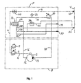
- FIG. 1 in one and the same schematic diagram shows the components and line system layout for the pneumatic circuit and hydraulic circuit forming part of a device according to the invention.
- a manually adjustable two-way valve 10 having five connections, of which the two upper ones (in the figure) are connected to a suction-side inlet 12 and a pressure-side outlet 14 of the hydraulic pump 2 by way of lines 16 and 18 respectively. Also coupled into the line 18 are a pressure regulator 20 and a pressure gauge 22.
- the three lower connections of the 5/2 valve 10 are connected via lines 24, 26, 28 to a first brake fluid connection 30, a second brake fluid connection 32 and a third brake fluid connection 34.
- V the rear wall of the apparatus housing denoted by V there is furthermore a main connection 42 for connecting the apparatus/the device to an external compressed air system on the premises where the apparatus is in use.
- the first brake fluid connection 30 is used to connect the device either to a brake fluid reservoir (expansion vessel) forming part of the vehicle hydraulic system, or to a bleed nipple on that cylinder of the vehicle wheel brake cylinders that is to be bled.
- the second brake fluid connection 32 is used when the device is to be connected to a collecting vessel for drawing off old brake fluid from the brake system of the vehicle in question.
- the third brake fluid connection 34 is used to connect the device to a container with fresh brake fluid with which the vehicle brake system is to be refilled in order to replace old brake fluid that has been drawn off therefrom.
- the device is made ready for use by coupling a suction hose between the connection 34 and said container containing fresh brake fluid.
- the device must then be switched off by setting a selector switch 44 (see Fig. 2 ) to the Off position.
- the external compressed air system is then connected to the connection 42.
- the device is then usually first used to extract old brake fluid out of the brake fluid reservoir of the vehicle in question by means of a vacuum.
- the brake fluid collecting vessel is then connected via a hose to the connection 32, following which the brake fluid reservoir is connected to the connection 30.
- Old brake fluid is then extracted from the brake fluid reservoir, following which the selector switch is set to the Off position.
- the next step in using the device is to refill the brake fluid reservoir with fresh brake fluid.
- the selector switch 46 is set to the Pressure position, that is to say the valve 10 is switched to the right from the position shown in Fig. 1 .
- the selector switch 44 is set to the On position, and the brake fluid reservoir is refilled via a filling hose from the connection 30.
- the selector switch 44 is set to the Off position, following which the selector switch 48 is set to the System Relief position.
- a suitable adapter has to be screwed pressure-tight on to the brake fluid reservoir filling connection, following which a hose is connected between the adapter and the connection 30.
- the selector switch 46 is set to the Pressure position, and the selector switch 48 is set to the System Close position, whilst the selector switch 44 is set to the On position.
- the required brake fluid pressure is set by means of the regulator 20, and the brake fluid collecting vessel is connected via a hose to the bleed nipple on the brake cylinder of the wheel in question, following which the nipple is opened and brake fluid is drawn off for bleeding purposes, all in accordance with the vehicle manufacturer's service specifications.
- the selector switch 44 is set to the Off position, and the selector switch 48 is set to the System Relief position, following which the hose between the adapter and the connection 30 is removed and the adapter is unscrewed from the brake fluid reservoir, which is then sealed with its usual sealing cap.
- the device is used for vacuum bleeding of the vehicle brake system.
- a separate brake fluid filling device is fitted to the filling connection of the brake fluid reservoir, and a bleed hose is connected to the connection 30, whereupon the brake fluid collecting vessel is connected to the connection 32.
- the selector switch 46 is set to the Vacuum position, and the selector switch 48 to the System Close position, following which the other end of the bleed hose is connected to the bleed nipple in question.
- the selector switch 44 is set to the On position and the brake cylinder is bled according to the manufacturer's instructions.
- the vacuum bleeding procedure is then repeated in the same way for the brake cylinders of the other wheels, following which the selector switch 44 is set to the Off position, and the brake fluid filling device is detached from the brake fluid reservoir, which is then sealed with its usual cap.
Landscapes
- Engineering & Computer Science (AREA)
- Transportation (AREA)
- Mechanical Engineering (AREA)
- Valves And Accessory Devices For Braking Systems (AREA)
- Lubricants (AREA)
- Fluid-Pressure Circuits (AREA)
- Centrifugal Separators (AREA)
- Electrical Discharge Machining, Electrochemical Machining, And Combined Machining (AREA)
- Braking Arrangements (AREA)
Claims (6)
- Dispositif pour soutirer le fluide hydraulique d'un circuit de frein hydraulique pour les freins de roue d'un véhicule et pour remplir à nouveau le circuit avec le fluide hydraulique, et pour purger l'air du fluide hydraulique dans le circuit de frein, caractérisé par un circuit pneumatique ayant des éléments de conduite (4) à partir d'un raccordement d'air comprimé (42) jusqu'à un élément entraîné par air comprimé (2), tel qu'une pompe hydraulique entraînée par air comprimé, qui est couplé dans un circuit hydraulique faisant partie du dispositif et qui sert à générer à la fois la pression en excès et le vide dans le circuit hydraulique du dispositif, ce circuit hydraulique étant prévu avec un premier raccordement de liquide de frein (30) pour le raccordement d'un réservoir de liquide de frein faisant partie du circuit de frein du véhicule en question ou d'un raccord de purge sur l'un quelconque des freins de roue de véhicule ; un deuxième raccordement de liquide de frein (32) pour purger l'ancien liquide de frein du circuit de frein par l'intermédiaire du circuit hydraulique du dispositif ; un troisième raccordement de liquide de frein (34) pour alimenter le nouveau liquide de frein au circuit de frein de véhicule par l'intermédiaire du circuit hydraulique du dispositif, le circuit hydraulique comprenant une soupape à deux voies manuellement ajustable (10) qui, dans une position ouvre un raccordement pour extraire l'ancien liquide de frein du réservoir de liquide de frein et dans son autre position, ouvre un raccordement pour remplir à nouveau le réservoir de liquide de frein avec le nouveau liquide de frein.
- Dispositif selon la revendication 1, caractérisé en ce que l'élément de conduite de circuit pneumatique (4) allant du raccordement d'air comprimé (42) à l'élément entraîné par air comprimé (2) comprend une soupape d'arrêt manuelle (40), telle qu'une soupape à bille, et un régulateur de pression (6) prévu avec une soupape de dégagement de pression (8).
- Dispositif selon la revendication 1 ou 2, caractérisé en ce que la soupape à deux voies de circuit hydraulique (10) est une soupape 5/2, l'élément entraîné par air comprimé étant une pompe hydraulique (2), dont le côté d'aspiration (12) et le côté de pression (14) sont chacun raccordés (16 et 18 respectivement) à un raccordement séparé d'un côté de la soupape à deux voies, alors que les trois raccordements du côté opposé de la soupape (10) sont chacun raccordés (24, 26 et 28) aux trois raccordements de liquide de frein séparés (30, 32 et 34 respectivement) du circuit hydraulique.
- Dispositif selon la revendication 3, caractérisé en ce que le raccordement (18) entre le côté de pression (14) de la pompe (2) et la soupape 5/2 (10) comprend un régulateur de pression (20) et une jauge de pression (22).
- Dispositif selon la revendication 3 ou 4, caractérisé en ce qu'une soupape d'arrêt manuelle (38) est insérée entre le raccordement (28) entre le troisième raccordement de liquide de frein (34) et la soupape 5/2 (10) d'un côté, et le raccordement (24) entre le premier raccordement de liquide de frein (30) et la soupape 5/2 (10) de l'autre côté.
- Dispositif selon l'une quelconque des revendications précédentes, caractérisé en ce que l'élément entraîné par air comprimé (2) est une pompe à membrane ou une pompe à double membrane.
Applications Claiming Priority (3)
| Application Number | Priority Date | Filing Date | Title |
|---|---|---|---|
| SE0202670 | 2002-09-10 | ||
| SE0202670A SE524082C2 (sv) | 2002-09-10 | 2002-09-10 | Anordning för avtapping/påfyllning och avluftning av bromsvätska |
| PCT/SE2003/001377 WO2004024526A1 (fr) | 2002-09-10 | 2003-09-04 | Dispositif conçu pour purger/remplir et evacuer le liquide de frein |
Publications (2)
| Publication Number | Publication Date |
|---|---|
| EP1539554A1 EP1539554A1 (fr) | 2005-06-15 |
| EP1539554B1 true EP1539554B1 (fr) | 2011-04-20 |
Family
ID=20288941
Family Applications (1)
| Application Number | Title | Priority Date | Filing Date |
|---|---|---|---|
| EP03795520A Expired - Lifetime EP1539554B1 (fr) | 2002-09-10 | 2003-09-04 | Dispositif concu pour purger/remplir et evacuer le liquide de frein |
Country Status (8)
| Country | Link |
|---|---|
| US (1) | US7281551B2 (fr) |
| EP (1) | EP1539554B1 (fr) |
| JP (1) | JP2005537977A (fr) |
| AT (1) | ATE506233T1 (fr) |
| AU (1) | AU2003261689A1 (fr) |
| DE (1) | DE60336825D1 (fr) |
| SE (1) | SE524082C2 (fr) |
| WO (1) | WO2004024526A1 (fr) |
Cited By (1)
| Publication number | Priority date | Publication date | Assignee | Title |
|---|---|---|---|---|
| EP4321400B1 (fr) * | 2022-08-08 | 2025-11-05 | Volvo Car Corporation | Équipement, système, procédé et support de stockage lisible par ordinateur pour remplir et purger un fluide de freinage |
Families Citing this family (4)
| Publication number | Priority date | Publication date | Assignee | Title |
|---|---|---|---|---|
| US7357161B2 (en) * | 2006-02-02 | 2008-04-15 | Norco Industries, Inc. | Brake flush machine with ordered cylinder extraction |
| US8215343B2 (en) * | 2007-08-01 | 2012-07-10 | Rti Technologies, Inc. | Automotive service equipment and method for brake fluid exchange with wireless brake bleeding system |
| DE102016214560A1 (de) * | 2016-08-05 | 2018-02-08 | Voith Patent Gmbh | Verfahren und Vorrichtung zum Reinigen und/oder Austausch von Hydrauliköl in hydraulischen Antrieben |
| FR3112178B1 (fr) * | 2020-07-02 | 2022-07-29 | Safran Landing Systems | Dispositif de remplissage d’un circuit hydraulique d’un système électro-hydrostatique et procédé de remplissage mettant en œuvre un tel dispositif |
Family Cites Families (15)
| Publication number | Priority date | Publication date | Assignee | Title |
|---|---|---|---|---|
| DE2641198C3 (de) | 1976-06-22 | 1979-03-15 | Joma-Maschinenbau Karl Jost, 7531 Tiefenbronn | Vorrichtung zum Füllen und Entlüften einer hydraulischen Bremsanlage, insbesondere einer Kraftfahrzeugbremsanlage |
| US4415071A (en) * | 1981-07-27 | 1983-11-15 | Butler Eric S | Device for bleeding brakes and refilling brake system |
| US5060703A (en) * | 1988-08-31 | 1991-10-29 | Arthur Koerner | Apparatus for filling hydraulic systems |
| DE4031098A1 (de) | 1990-10-02 | 1992-04-09 | Horst Pehl | Vorrichtung zum entleeren, fuellen und entlueften einer hydraulischen bremsanlage, insbesondere fuer kraftfahrzeuge aller art |
| JP2557294B2 (ja) * | 1991-07-08 | 1996-11-27 | 本田技研工業株式会社 | 自動二・三輪車の作動油充填方法ならびに該方法に使用する作動油充填装置および注油ガン |
| DE19531468B4 (de) | 1995-08-26 | 2007-05-24 | Robert Bosch Gmbh | Hydraulikaggregat für eine Bremsanlage mit einer Blockierschutzeinrichtung |
| DE19654087A1 (de) * | 1996-12-23 | 1998-06-25 | Teves Gmbh Alfred | Verfahren zur blasenfreien Befüllung einer hydraulischen Kraftfahrzeugbremsanlage mit Bremsflüssigkeit |
| JPH11148350A (ja) * | 1997-11-17 | 1999-06-02 | Mk Seiko Co Ltd | 車両用エンジンの冷却液交換装置 |
| US6206055B1 (en) | 1998-10-08 | 2001-03-27 | Peter C. Hollub | Apparatus and method for removing and replacing vehicle hydraulic fluid |
| JP2000247396A (ja) * | 1999-02-26 | 2000-09-12 | Tokico Ltd | 液体供給装置 |
| US6302167B1 (en) * | 2000-01-13 | 2001-10-16 | Peter C. Hollub | Apparatus and method for removing and replacing vehicular hydraulic fluid while flushing the hydraulic system |
| JP3526823B2 (ja) * | 2000-09-08 | 2004-05-17 | 柴田産業株式会社 | オイル交換装置 |
| US6796339B1 (en) * | 2003-07-03 | 2004-09-28 | Phoenix Systems, L.L.C. | Apparatus for flushing, replacing fluid and bleeding hydraulic systems |
| US6929036B2 (en) * | 2003-09-17 | 2005-08-16 | Adam Awad | Automotive fluid exchange system and method of use |
| US7004206B2 (en) * | 2004-01-29 | 2006-02-28 | Viken James P | Automatic fluid exchanger |
-
2002
- 2002-09-10 SE SE0202670A patent/SE524082C2/sv not_active IP Right Cessation
-
2003
- 2003-09-04 US US10/533,379 patent/US7281551B2/en not_active Expired - Fee Related
- 2003-09-04 AT AT03795520T patent/ATE506233T1/de not_active IP Right Cessation
- 2003-09-04 DE DE60336825T patent/DE60336825D1/de not_active Expired - Lifetime
- 2003-09-04 EP EP03795520A patent/EP1539554B1/fr not_active Expired - Lifetime
- 2003-09-04 JP JP2004535317A patent/JP2005537977A/ja active Pending
- 2003-09-04 AU AU2003261689A patent/AU2003261689A1/en not_active Abandoned
- 2003-09-04 WO PCT/SE2003/001377 patent/WO2004024526A1/fr not_active Ceased
Cited By (1)
| Publication number | Priority date | Publication date | Assignee | Title |
|---|---|---|---|---|
| EP4321400B1 (fr) * | 2022-08-08 | 2025-11-05 | Volvo Car Corporation | Équipement, système, procédé et support de stockage lisible par ordinateur pour remplir et purger un fluide de freinage |
Also Published As
| Publication number | Publication date |
|---|---|
| SE524082C2 (sv) | 2004-06-22 |
| SE0202670L (sv) | 2004-03-11 |
| US20060196572A1 (en) | 2006-09-07 |
| SE0202670D0 (sv) | 2002-09-10 |
| US7281551B2 (en) | 2007-10-16 |
| JP2005537977A (ja) | 2005-12-15 |
| WO2004024526A1 (fr) | 2004-03-25 |
| DE60336825D1 (de) | 2011-06-01 |
| ATE506233T1 (de) | 2011-05-15 |
| EP1539554A1 (fr) | 2005-06-15 |
| AU2003261689A1 (en) | 2004-04-30 |
Similar Documents
| Publication | Publication Date | Title |
|---|---|---|
| CN105365504B (zh) | 用于空气维持轮胎的阀杆定位的控制调节器 | |
| CA2267203A1 (fr) | Dispositif de freinage | |
| EP1788288A3 (fr) | Circuit hydraulique avec deux pressions et deux pompes | |
| US6199958B1 (en) | Hydraulic unit | |
| US4038823A (en) | Method of bleeding a hydraulic system and means therefor | |
| EP1539554B1 (fr) | Dispositif concu pour purger/remplir et evacuer le liquide de frein | |
| US2670874A (en) | Hydraulic brake system bleeding and filling apparatus | |
| EP0292488B1 (fr) | Appareil de purge pour circuits a fluide | |
| US6929036B2 (en) | Automotive fluid exchange system and method of use | |
| US20200240298A1 (en) | Oil storage and filtration system | |
| JP3526823B2 (ja) | オイル交換装置 | |
| US4655328A (en) | Hydraulic brake bleeding apparatus | |
| CN210258371U (zh) | 一种大中型飞机充气装置 | |
| CN2233333Y (zh) | 可加压排气的汽车液压操纵机构 | |
| CN219098742U (zh) | 一种汽车制动液抽加一体装置 | |
| CN111137255A (zh) | 一种车辆制动液置换机及置换方法 | |
| CN214450889U (zh) | 一种离合器及液压制动系统排气装置 | |
| US2571420A (en) | Mechanism for draining moisture from compressed-air storage tanks | |
| CA2142260A1 (fr) | Regulateur de pression pour liquide de frein | |
| CN105711577B (zh) | 一种汽车刹车液压辅助装置及分油阀 | |
| EP0970863A3 (fr) | Valve à solénoide de commande de freinage pour système de freinage électronique pour wagons ferroviaires | |
| CN216946188U (zh) | 一种用于排放和收集报废汽车刹车油的装置 | |
| CN203094039U (zh) | 一种双管路气液制动系统 | |
| CN212556762U (zh) | 一种飞机刹车液压系统打压装置 | |
| CN206681933U (zh) | 发动机空压机 |
Legal Events
| Date | Code | Title | Description |
|---|---|---|---|
| PUAI | Public reference made under article 153(3) epc to a published international application that has entered the european phase |
Free format text: ORIGINAL CODE: 0009012 |
|
| 17P | Request for examination filed |
Effective date: 20050329 |
|
| AK | Designated contracting states |
Kind code of ref document: A1 Designated state(s): AT BE BG CH CY CZ DE DK EE ES FI FR GB GR HU IE IT LI LU MC NL PT RO SE SI SK TR |
|
| AX | Request for extension of the european patent |
Extension state: AL LT LV MK |
|
| DAX | Request for extension of the european patent (deleted) | ||
| GRAP | Despatch of communication of intention to grant a patent |
Free format text: ORIGINAL CODE: EPIDOSNIGR1 |
|
| GRAS | Grant fee paid |
Free format text: ORIGINAL CODE: EPIDOSNIGR3 |
|
| RAP1 | Party data changed (applicant data changed or rights of an application transferred) |
Owner name: CEJN AB |
|
| GRAA | (expected) grant |
Free format text: ORIGINAL CODE: 0009210 |
|
| RAP1 | Party data changed (applicant data changed or rights of an application transferred) |
Owner name: SYKES-PICKAVANT LTD |
|
| AK | Designated contracting states |
Kind code of ref document: B1 Designated state(s): AT BE BG CH CY CZ DE DK EE ES FI FR GB GR HU IE IT LI LU MC NL PT RO SE SI SK TR |
|
| REG | Reference to a national code |
Ref country code: GB Ref legal event code: FG4D |
|
| REG | Reference to a national code |
Ref country code: CH Ref legal event code: EP |
|
| REG | Reference to a national code |
Ref country code: IE Ref legal event code: FG4D |
|
| REF | Corresponds to: |
Ref document number: 60336825 Country of ref document: DE Date of ref document: 20110601 Kind code of ref document: P |
|
| REG | Reference to a national code |
Ref country code: DE Ref legal event code: R096 Ref document number: 60336825 Country of ref document: DE Effective date: 20110601 |
|
| REG | Reference to a national code |
Ref country code: SE Ref legal event code: TRGR |
|
| REG | Reference to a national code |
Ref country code: NL Ref legal event code: VDEP Effective date: 20110420 |
|
| PG25 | Lapsed in a contracting state [announced via postgrant information from national office to epo] |
Ref country code: PT Free format text: LAPSE BECAUSE OF FAILURE TO SUBMIT A TRANSLATION OF THE DESCRIPTION OR TO PAY THE FEE WITHIN THE PRESCRIBED TIME-LIMIT Effective date: 20110822 |
|
| PG25 | Lapsed in a contracting state [announced via postgrant information from national office to epo] |
Ref country code: ES Free format text: LAPSE BECAUSE OF FAILURE TO SUBMIT A TRANSLATION OF THE DESCRIPTION OR TO PAY THE FEE WITHIN THE PRESCRIBED TIME-LIMIT Effective date: 20110731 Ref country code: GR Free format text: LAPSE BECAUSE OF FAILURE TO SUBMIT A TRANSLATION OF THE DESCRIPTION OR TO PAY THE FEE WITHIN THE PRESCRIBED TIME-LIMIT Effective date: 20110721 Ref country code: FI Free format text: LAPSE BECAUSE OF FAILURE TO SUBMIT A TRANSLATION OF THE DESCRIPTION OR TO PAY THE FEE WITHIN THE PRESCRIBED TIME-LIMIT Effective date: 20110420 Ref country code: SI Free format text: LAPSE BECAUSE OF FAILURE TO SUBMIT A TRANSLATION OF THE DESCRIPTION OR TO PAY THE FEE WITHIN THE PRESCRIBED TIME-LIMIT Effective date: 20110420 Ref country code: AT Free format text: LAPSE BECAUSE OF FAILURE TO SUBMIT A TRANSLATION OF THE DESCRIPTION OR TO PAY THE FEE WITHIN THE PRESCRIBED TIME-LIMIT Effective date: 20110420 Ref country code: CY Free format text: LAPSE BECAUSE OF FAILURE TO SUBMIT A TRANSLATION OF THE DESCRIPTION OR TO PAY THE FEE WITHIN THE PRESCRIBED TIME-LIMIT Effective date: 20110420 Ref country code: BE Free format text: LAPSE BECAUSE OF FAILURE TO SUBMIT A TRANSLATION OF THE DESCRIPTION OR TO PAY THE FEE WITHIN THE PRESCRIBED TIME-LIMIT Effective date: 20110420 |
|
| PG25 | Lapsed in a contracting state [announced via postgrant information from national office to epo] |
Ref country code: NL Free format text: LAPSE BECAUSE OF FAILURE TO SUBMIT A TRANSLATION OF THE DESCRIPTION OR TO PAY THE FEE WITHIN THE PRESCRIBED TIME-LIMIT Effective date: 20110420 |
|
| PG25 | Lapsed in a contracting state [announced via postgrant information from national office to epo] |
Ref country code: CZ Free format text: LAPSE BECAUSE OF FAILURE TO SUBMIT A TRANSLATION OF THE DESCRIPTION OR TO PAY THE FEE WITHIN THE PRESCRIBED TIME-LIMIT Effective date: 20110420 Ref country code: EE Free format text: LAPSE BECAUSE OF FAILURE TO SUBMIT A TRANSLATION OF THE DESCRIPTION OR TO PAY THE FEE WITHIN THE PRESCRIBED TIME-LIMIT Effective date: 20110420 |
|
| PLBE | No opposition filed within time limit |
Free format text: ORIGINAL CODE: 0009261 |
|
| STAA | Information on the status of an ep patent application or granted ep patent |
Free format text: STATUS: NO OPPOSITION FILED WITHIN TIME LIMIT |
|
| PG25 | Lapsed in a contracting state [announced via postgrant information from national office to epo] |
Ref country code: DK Free format text: LAPSE BECAUSE OF FAILURE TO SUBMIT A TRANSLATION OF THE DESCRIPTION OR TO PAY THE FEE WITHIN THE PRESCRIBED TIME-LIMIT Effective date: 20110420 Ref country code: SK Free format text: LAPSE BECAUSE OF FAILURE TO SUBMIT A TRANSLATION OF THE DESCRIPTION OR TO PAY THE FEE WITHIN THE PRESCRIBED TIME-LIMIT Effective date: 20110420 Ref country code: RO Free format text: LAPSE BECAUSE OF FAILURE TO SUBMIT A TRANSLATION OF THE DESCRIPTION OR TO PAY THE FEE WITHIN THE PRESCRIBED TIME-LIMIT Effective date: 20110420 |
|
| 26N | No opposition filed |
Effective date: 20120123 |
|
| PG25 | Lapsed in a contracting state [announced via postgrant information from national office to epo] |
Ref country code: MC Free format text: LAPSE BECAUSE OF NON-PAYMENT OF DUE FEES Effective date: 20110930 |
|
| REG | Reference to a national code |
Ref country code: CH Ref legal event code: PL |
|
| REG | Reference to a national code |
Ref country code: DE Ref legal event code: R097 Ref document number: 60336825 Country of ref document: DE Effective date: 20120123 |
|
| GBPC | Gb: european patent ceased through non-payment of renewal fee |
Effective date: 20110904 |
|
| PG25 | Lapsed in a contracting state [announced via postgrant information from national office to epo] |
Ref country code: IT Free format text: LAPSE BECAUSE OF FAILURE TO SUBMIT A TRANSLATION OF THE DESCRIPTION OR TO PAY THE FEE WITHIN THE PRESCRIBED TIME-LIMIT Effective date: 20110420 |
|
| REG | Reference to a national code |
Ref country code: IE Ref legal event code: MM4A |
|
| REG | Reference to a national code |
Ref country code: FR Ref legal event code: ST Effective date: 20120531 |
|
| REG | Reference to a national code |
Ref country code: SE Ref legal event code: EUG |
|
| REG | Reference to a national code |
Ref country code: DE Ref legal event code: R119 Ref document number: 60336825 Country of ref document: DE Effective date: 20120403 |
|
| PG25 | Lapsed in a contracting state [announced via postgrant information from national office to epo] |
Ref country code: IE Free format text: LAPSE BECAUSE OF NON-PAYMENT OF DUE FEES Effective date: 20110904 Ref country code: DE Free format text: LAPSE BECAUSE OF NON-PAYMENT OF DUE FEES Effective date: 20120403 Ref country code: CH Free format text: LAPSE BECAUSE OF NON-PAYMENT OF DUE FEES Effective date: 20110930 Ref country code: LI Free format text: LAPSE BECAUSE OF NON-PAYMENT OF DUE FEES Effective date: 20110930 |
|
| PG25 | Lapsed in a contracting state [announced via postgrant information from national office to epo] |
Ref country code: GB Free format text: LAPSE BECAUSE OF NON-PAYMENT OF DUE FEES Effective date: 20110904 Ref country code: FR Free format text: LAPSE BECAUSE OF NON-PAYMENT OF DUE FEES Effective date: 20110930 |
|
| PG25 | Lapsed in a contracting state [announced via postgrant information from national office to epo] |
Ref country code: SE Free format text: LAPSE BECAUSE OF NON-PAYMENT OF DUE FEES Effective date: 20110905 |
|
| PG25 | Lapsed in a contracting state [announced via postgrant information from national office to epo] |
Ref country code: LU Free format text: LAPSE BECAUSE OF NON-PAYMENT OF DUE FEES Effective date: 20110904 |
|
| PG25 | Lapsed in a contracting state [announced via postgrant information from national office to epo] |
Ref country code: BG Free format text: LAPSE BECAUSE OF FAILURE TO SUBMIT A TRANSLATION OF THE DESCRIPTION OR TO PAY THE FEE WITHIN THE PRESCRIBED TIME-LIMIT Effective date: 20110720 |
|
| PG25 | Lapsed in a contracting state [announced via postgrant information from national office to epo] |
Ref country code: TR Free format text: LAPSE BECAUSE OF FAILURE TO SUBMIT A TRANSLATION OF THE DESCRIPTION OR TO PAY THE FEE WITHIN THE PRESCRIBED TIME-LIMIT Effective date: 20110420 |
|
| PG25 | Lapsed in a contracting state [announced via postgrant information from national office to epo] |
Ref country code: HU Free format text: LAPSE BECAUSE OF FAILURE TO SUBMIT A TRANSLATION OF THE DESCRIPTION OR TO PAY THE FEE WITHIN THE PRESCRIBED TIME-LIMIT Effective date: 20110420 |