EP1539399B1 - Verfahren und vorrichtung zum schmelzen von titan unter verwendung einer kombination aus plasmafackeln und direktlichtbogenelektroden - Google Patents
Verfahren und vorrichtung zum schmelzen von titan unter verwendung einer kombination aus plasmafackeln und direktlichtbogenelektroden Download PDFInfo
- Publication number
- EP1539399B1 EP1539399B1 EP03811656A EP03811656A EP1539399B1 EP 1539399 B1 EP1539399 B1 EP 1539399B1 EP 03811656 A EP03811656 A EP 03811656A EP 03811656 A EP03811656 A EP 03811656A EP 1539399 B1 EP1539399 B1 EP 1539399B1
- Authority
- EP
- European Patent Office
- Prior art keywords
- mold
- hearth
- plasma torch
- direct arc
- main hearth
- Prior art date
- Legal status (The legal status is an assumption and is not a legal conclusion. Google has not performed a legal analysis and makes no representation as to the accuracy of the status listed.)
- Expired - Lifetime
Links
- 238000002844 melting Methods 0.000 title claims abstract description 68
- 230000008018 melting Effects 0.000 title claims abstract description 66
- RTAQQCXQSZGOHL-UHFFFAOYSA-N Titanium Chemical compound [Ti] RTAQQCXQSZGOHL-UHFFFAOYSA-N 0.000 title claims abstract description 39
- 229910052719 titanium Inorganic materials 0.000 title claims abstract description 39
- 239000010936 titanium Substances 0.000 title claims abstract description 39
- 238000000034 method Methods 0.000 title claims abstract description 36
- 238000010438 heat treatment Methods 0.000 claims description 15
- 229910052751 metal Inorganic materials 0.000 claims description 11
- 239000002184 metal Substances 0.000 claims description 11
- 239000012768 molten material Substances 0.000 claims description 7
- 229910001069 Ti alloy Inorganic materials 0.000 claims description 5
- 229910001092 metal group alloy Inorganic materials 0.000 claims description 5
- 239000012530 fluid Substances 0.000 claims 1
- 238000005266 casting Methods 0.000 abstract description 26
- 238000007670 refining Methods 0.000 abstract description 11
- 239000007795 chemical reaction product Substances 0.000 abstract description 4
- 230000008569 process Effects 0.000 description 22
- 229910045601 alloy Inorganic materials 0.000 description 18
- 239000000956 alloy Substances 0.000 description 18
- 238000010894 electron beam technology Methods 0.000 description 18
- 239000000463 material Substances 0.000 description 12
- 238000004519 manufacturing process Methods 0.000 description 9
- 230000007246 mechanism Effects 0.000 description 7
- 239000000047 product Substances 0.000 description 7
- 229910052782 aluminium Inorganic materials 0.000 description 6
- XAGFODPZIPBFFR-UHFFFAOYSA-N aluminium Chemical compound [Al] XAGFODPZIPBFFR-UHFFFAOYSA-N 0.000 description 6
- 239000000155 melt Substances 0.000 description 6
- 238000003756 stirring Methods 0.000 description 6
- 238000007514 turning Methods 0.000 description 6
- 238000013461 design Methods 0.000 description 5
- 238000001704 evaporation Methods 0.000 description 5
- 230000008020 evaporation Effects 0.000 description 5
- IJGRMHOSHXDMSA-UHFFFAOYSA-N Atomic nitrogen Chemical compound N#N IJGRMHOSHXDMSA-UHFFFAOYSA-N 0.000 description 4
- PXHVJJICTQNCMI-UHFFFAOYSA-N Nickel Chemical compound [Ni] PXHVJJICTQNCMI-UHFFFAOYSA-N 0.000 description 4
- QVGXLLKOCUKJST-UHFFFAOYSA-N atomic oxygen Chemical compound [O] QVGXLLKOCUKJST-UHFFFAOYSA-N 0.000 description 4
- 230000008901 benefit Effects 0.000 description 4
- 238000011109 contamination Methods 0.000 description 4
- 230000007547 defect Effects 0.000 description 4
- 238000002156 mixing Methods 0.000 description 4
- 239000001301 oxygen Substances 0.000 description 4
- 229910052760 oxygen Inorganic materials 0.000 description 4
- 239000002994 raw material Substances 0.000 description 4
- 210000003625 skull Anatomy 0.000 description 4
- RYGMFSIKBFXOCR-UHFFFAOYSA-N Copper Chemical compound [Cu] RYGMFSIKBFXOCR-UHFFFAOYSA-N 0.000 description 3
- ZOKXTWBITQBERF-UHFFFAOYSA-N Molybdenum Chemical compound [Mo] ZOKXTWBITQBERF-UHFFFAOYSA-N 0.000 description 3
- 238000007792 addition Methods 0.000 description 3
- 238000010276 construction Methods 0.000 description 3
- 238000010924 continuous production Methods 0.000 description 3
- 229910052802 copper Inorganic materials 0.000 description 3
- 239000010949 copper Substances 0.000 description 3
- 238000001698 laser desorption ionisation Methods 0.000 description 3
- 238000010309 melting process Methods 0.000 description 3
- 239000000203 mixture Substances 0.000 description 3
- 229910052750 molybdenum Inorganic materials 0.000 description 3
- 239000011733 molybdenum Substances 0.000 description 3
- 229910052715 tantalum Inorganic materials 0.000 description 3
- GUVRBAGPIYLISA-UHFFFAOYSA-N tantalum atom Chemical compound [Ta] GUVRBAGPIYLISA-UHFFFAOYSA-N 0.000 description 3
- WFKWXMTUELFFGS-UHFFFAOYSA-N tungsten Chemical compound [W] WFKWXMTUELFFGS-UHFFFAOYSA-N 0.000 description 3
- 229910052721 tungsten Inorganic materials 0.000 description 3
- 239000010937 tungsten Substances 0.000 description 3
- 230000009471 action Effects 0.000 description 2
- 238000002485 combustion reaction Methods 0.000 description 2
- 238000007689 inspection Methods 0.000 description 2
- 238000002955 isolation Methods 0.000 description 2
- 238000003754 machining Methods 0.000 description 2
- 150000002739 metals Chemical class 0.000 description 2
- 229910052759 nickel Inorganic materials 0.000 description 2
- 229910052757 nitrogen Inorganic materials 0.000 description 2
- 239000002245 particle Substances 0.000 description 2
- 238000002360 preparation method Methods 0.000 description 2
- 238000000926 separation method Methods 0.000 description 2
- 238000009987 spinning Methods 0.000 description 2
- 230000002269 spontaneous effect Effects 0.000 description 2
- 238000003860 storage Methods 0.000 description 2
- 230000007704 transition Effects 0.000 description 2
- UONOETXJSWQNOL-UHFFFAOYSA-N tungsten carbide Chemical compound [W+]#[C-] UONOETXJSWQNOL-UHFFFAOYSA-N 0.000 description 2
- XLYOFNOQVPJJNP-UHFFFAOYSA-N water Substances O XLYOFNOQVPJJNP-UHFFFAOYSA-N 0.000 description 2
- 229910000851 Alloy steel Inorganic materials 0.000 description 1
- OKTJSMMVPCPJKN-UHFFFAOYSA-N Carbon Chemical compound [C] OKTJSMMVPCPJKN-UHFFFAOYSA-N 0.000 description 1
- QCWXUUIWCKQGHC-UHFFFAOYSA-N Zirconium Chemical compound [Zr] QCWXUUIWCKQGHC-UHFFFAOYSA-N 0.000 description 1
- 238000013019 agitation Methods 0.000 description 1
- 238000010923 batch production Methods 0.000 description 1
- XMQFTWRPUQYINF-UHFFFAOYSA-N bensulfuron-methyl Chemical compound COC(=O)C1=CC=CC=C1CS(=O)(=O)NC(=O)NC1=NC(OC)=CC(OC)=N1 XMQFTWRPUQYINF-UHFFFAOYSA-N 0.000 description 1
- 238000007664 blowing Methods 0.000 description 1
- 229910052799 carbon Inorganic materials 0.000 description 1
- 239000000470 constituent Substances 0.000 description 1
- 238000009749 continuous casting Methods 0.000 description 1
- 239000002826 coolant Substances 0.000 description 1
- 230000003247 decreasing effect Effects 0.000 description 1
- 230000001627 detrimental effect Effects 0.000 description 1
- 238000007599 discharging Methods 0.000 description 1
- 238000004090 dissolution Methods 0.000 description 1
- 238000011143 downstream manufacturing Methods 0.000 description 1
- 239000000428 dust Substances 0.000 description 1
- 230000008030 elimination Effects 0.000 description 1
- 238000003379 elimination reaction Methods 0.000 description 1
- 239000008240 homogeneous mixture Substances 0.000 description 1
- 239000012535 impurity Substances 0.000 description 1
- 239000011261 inert gas Substances 0.000 description 1
- 238000003780 insertion Methods 0.000 description 1
- 230000037431 insertion Effects 0.000 description 1
- 239000007788 liquid Substances 0.000 description 1
- 230000003340 mental effect Effects 0.000 description 1
- 229910052758 niobium Inorganic materials 0.000 description 1
- 239000010955 niobium Substances 0.000 description 1
- GUCVJGMIXFAOAE-UHFFFAOYSA-N niobium atom Chemical compound [Nb] GUCVJGMIXFAOAE-UHFFFAOYSA-N 0.000 description 1
- 229910000510 noble metal Inorganic materials 0.000 description 1
- 238000005457 optimization Methods 0.000 description 1
- 230000009467 reduction Effects 0.000 description 1
- 230000000630 rising effect Effects 0.000 description 1
- 238000005204 segregation Methods 0.000 description 1
- 238000007493 shaping process Methods 0.000 description 1
- 239000010802 sludge Substances 0.000 description 1
- 239000007787 solid Substances 0.000 description 1
- 238000007711 solidification Methods 0.000 description 1
- 230000008023 solidification Effects 0.000 description 1
- 239000003381 stabilizer Substances 0.000 description 1
- 239000010935 stainless steel Substances 0.000 description 1
- 229910001220 stainless steel Inorganic materials 0.000 description 1
- 230000000153 supplemental effect Effects 0.000 description 1
- 238000012360 testing method Methods 0.000 description 1
- 239000002699 waste material Substances 0.000 description 1
- 229910052726 zirconium Inorganic materials 0.000 description 1
Images


Classifications
-
- B—PERFORMING OPERATIONS; TRANSPORTING
- B22—CASTING; POWDER METALLURGY
- B22D—CASTING OF METALS; CASTING OF OTHER SUBSTANCES BY THE SAME PROCESSES OR DEVICES
- B22D11/00—Continuous casting of metals, i.e. casting in indefinite lengths
- B22D11/001—Continuous casting of metals, i.e. casting in indefinite lengths of specific alloys
-
- B—PERFORMING OPERATIONS; TRANSPORTING
- B22—CASTING; POWDER METALLURGY
- B22D—CASTING OF METALS; CASTING OF OTHER SUBSTANCES BY THE SAME PROCESSES OR DEVICES
- B22D11/00—Continuous casting of metals, i.e. casting in indefinite lengths
- B22D11/04—Continuous casting of metals, i.e. casting in indefinite lengths into open-ended moulds
- B22D11/041—Continuous casting of metals, i.e. casting in indefinite lengths into open-ended moulds for vertical casting
-
- B—PERFORMING OPERATIONS; TRANSPORTING
- B22—CASTING; POWDER METALLURGY
- B22D—CASTING OF METALS; CASTING OF OTHER SUBSTANCES BY THE SAME PROCESSES OR DEVICES
- B22D11/00—Continuous casting of metals, i.e. casting in indefinite lengths
- B22D11/10—Supplying or treating molten metal
- B22D11/11—Treating the molten metal
- B22D11/116—Refining the metal
-
- C—CHEMISTRY; METALLURGY
- C22—METALLURGY; FERROUS OR NON-FERROUS ALLOYS; TREATMENT OF ALLOYS OR NON-FERROUS METALS
- C22B—PRODUCTION AND REFINING OF METALS; PRETREATMENT OF RAW MATERIALS
- C22B34/00—Obtaining refractory metals
- C22B34/10—Obtaining titanium, zirconium or hafnium
- C22B34/12—Obtaining titanium or titanium compounds from ores or scrap by metallurgical processing; preparation of titanium compounds from other titanium compounds see C01G23/00 - C01G23/08
- C22B34/1295—Refining, melting, remelting, working up of titanium
-
- C—CHEMISTRY; METALLURGY
- C22—METALLURGY; FERROUS OR NON-FERROUS ALLOYS; TREATMENT OF ALLOYS OR NON-FERROUS METALS
- C22B—PRODUCTION AND REFINING OF METALS; PRETREATMENT OF RAW MATERIALS
- C22B9/00—General processes of refining or remelting of metals; Apparatus for electroslag or arc remelting of metals
- C22B9/16—Remelting metals
- C22B9/22—Remelting metals with heating by wave energy or particle radiation
- C22B9/226—Remelting metals with heating by wave energy or particle radiation by electric discharge, e.g. plasma
-
- F—MECHANICAL ENGINEERING; LIGHTING; HEATING; WEAPONS; BLASTING
- F27—FURNACES; KILNS; OVENS; RETORTS
- F27B—FURNACES, KILNS, OVENS OR RETORTS IN GENERAL; OPEN SINTERING OR LIKE APPARATUS
- F27B14/00—Crucible or pot furnaces
- F27B14/04—Crucible or pot furnaces adapted for treating the charge in vacuum or special atmosphere
-
- F—MECHANICAL ENGINEERING; LIGHTING; HEATING; WEAPONS; BLASTING
- F27—FURNACES; KILNS; OVENS; RETORTS
- F27B—FURNACES, KILNS, OVENS OR RETORTS IN GENERAL; OPEN SINTERING OR LIKE APPARATUS
- F27B14/00—Crucible or pot furnaces
- F27B14/06—Crucible or pot furnaces heated electrically, e.g. induction crucible furnaces with or without any other source of heat
-
- F—MECHANICAL ENGINEERING; LIGHTING; HEATING; WEAPONS; BLASTING
- F27—FURNACES; KILNS; OVENS; RETORTS
- F27B—FURNACES, KILNS, OVENS OR RETORTS IN GENERAL; OPEN SINTERING OR LIKE APPARATUS
- F27B14/00—Crucible or pot furnaces
- F27B14/08—Details specially adapted for crucible or pot furnaces
- F27B14/0806—Charging or discharging devices
-
- F—MECHANICAL ENGINEERING; LIGHTING; HEATING; WEAPONS; BLASTING
- F27—FURNACES; KILNS; OVENS; RETORTS
- F27B—FURNACES, KILNS, OVENS OR RETORTS IN GENERAL; OPEN SINTERING OR LIKE APPARATUS
- F27B3/00—Hearth-type furnaces, e.g. of reverberatory type; Electric arc furnaces ; Tank furnaces
- F27B3/04—Hearth-type furnaces, e.g. of reverberatory type; Electric arc furnaces ; Tank furnaces of multiple-hearth type; of multiple-chamber type; Combinations of hearth-type furnaces
-
- F—MECHANICAL ENGINEERING; LIGHTING; HEATING; WEAPONS; BLASTING
- F27—FURNACES; KILNS; OVENS; RETORTS
- F27B—FURNACES, KILNS, OVENS OR RETORTS IN GENERAL; OPEN SINTERING OR LIKE APPARATUS
- F27B3/00—Hearth-type furnaces, e.g. of reverberatory type; Electric arc furnaces ; Tank furnaces
- F27B3/06—Hearth-type furnaces, e.g. of reverberatory type; Electric arc furnaces ; Tank furnaces with movable working chambers or hearths, e.g. tiltable, oscillating or describing a composed movement
- F27B3/065—Hearth-type furnaces, e.g. of reverberatory type; Electric arc furnaces ; Tank furnaces with movable working chambers or hearths, e.g. tiltable, oscillating or describing a composed movement tiltable
-
- F—MECHANICAL ENGINEERING; LIGHTING; HEATING; WEAPONS; BLASTING
- F27—FURNACES; KILNS; OVENS; RETORTS
- F27B—FURNACES, KILNS, OVENS OR RETORTS IN GENERAL; OPEN SINTERING OR LIKE APPARATUS
- F27B3/00—Hearth-type furnaces, e.g. of reverberatory type; Electric arc furnaces ; Tank furnaces
- F27B3/08—Hearth-type furnaces, e.g. of reverberatory type; Electric arc furnaces ; Tank furnaces heated electrically, with or without any other source of heat
- F27B3/085—Arc furnaces
-
- F—MECHANICAL ENGINEERING; LIGHTING; HEATING; WEAPONS; BLASTING
- F27—FURNACES; KILNS; OVENS; RETORTS
- F27B—FURNACES, KILNS, OVENS OR RETORTS IN GENERAL; OPEN SINTERING OR LIKE APPARATUS
- F27B3/00—Hearth-type furnaces, e.g. of reverberatory type; Electric arc furnaces ; Tank furnaces
- F27B3/10—Details, accessories or equipment, e.g. dust-collectors, specially adapted for hearth-type furnaces
- F27B3/18—Arrangements of devices for charging
-
- F—MECHANICAL ENGINEERING; LIGHTING; HEATING; WEAPONS; BLASTING
- F27—FURNACES; KILNS; OVENS; RETORTS
- F27B—FURNACES, KILNS, OVENS OR RETORTS IN GENERAL; OPEN SINTERING OR LIKE APPARATUS
- F27B3/00—Hearth-type furnaces, e.g. of reverberatory type; Electric arc furnaces ; Tank furnaces
- F27B3/10—Details, accessories or equipment, e.g. dust-collectors, specially adapted for hearth-type furnaces
- F27B3/19—Arrangements of devices for discharging
-
- F—MECHANICAL ENGINEERING; LIGHTING; HEATING; WEAPONS; BLASTING
- F27—FURNACES; KILNS; OVENS; RETORTS
- F27B—FURNACES, KILNS, OVENS OR RETORTS IN GENERAL; OPEN SINTERING OR LIKE APPARATUS
- F27B3/00—Hearth-type furnaces, e.g. of reverberatory type; Electric arc furnaces ; Tank furnaces
- F27B3/10—Details, accessories or equipment, e.g. dust-collectors, specially adapted for hearth-type furnaces
- F27B3/20—Arrangements of heating devices
-
- F—MECHANICAL ENGINEERING; LIGHTING; HEATING; WEAPONS; BLASTING
- F27—FURNACES; KILNS; OVENS; RETORTS
- F27D—DETAILS OR ACCESSORIES OF FURNACES, KILNS, OVENS OR RETORTS, IN SO FAR AS THEY ARE OF KINDS OCCURRING IN MORE THAN ONE KIND OF FURNACE
- F27D3/00—Charging; Discharging; Manipulation of charge
- F27D3/0025—Charging or loading melting furnaces with material in the solid state
-
- F—MECHANICAL ENGINEERING; LIGHTING; HEATING; WEAPONS; BLASTING
- F27—FURNACES; KILNS; OVENS; RETORTS
- F27D—DETAILS OR ACCESSORIES OF FURNACES, KILNS, OVENS OR RETORTS, IN SO FAR AS THEY ARE OF KINDS OCCURRING IN MORE THAN ONE KIND OF FURNACE
- F27D3/00—Charging; Discharging; Manipulation of charge
- F27D3/0033—Charging; Discharging; Manipulation of charge charging of particulate material
-
- F—MECHANICAL ENGINEERING; LIGHTING; HEATING; WEAPONS; BLASTING
- F27—FURNACES; KILNS; OVENS; RETORTS
- F27D—DETAILS OR ACCESSORIES OF FURNACES, KILNS, OVENS OR RETORTS, IN SO FAR AS THEY ARE OF KINDS OCCURRING IN MORE THAN ONE KIND OF FURNACE
- F27D3/00—Charging; Discharging; Manipulation of charge
- F27D3/06—Charging or discharging machines on travelling carriages
-
- F—MECHANICAL ENGINEERING; LIGHTING; HEATING; WEAPONS; BLASTING
- F27—FURNACES; KILNS; OVENS; RETORTS
- F27D—DETAILS OR ACCESSORIES OF FURNACES, KILNS, OVENS OR RETORTS, IN SO FAR AS THEY ARE OF KINDS OCCURRING IN MORE THAN ONE KIND OF FURNACE
- F27D3/00—Charging; Discharging; Manipulation of charge
- F27D3/10—Charging directly from hoppers or shoots
Definitions
- This invention relates to the melting of titanium or titanium alloys in a plasma cold hearth furnace. More particularly, this invention relates to a plasma cold hearth melting method and apparatus for providing a titanium ingot of commercial quality. Specifically, the invention is a method and apparatus for optimizing melting using a combination of plasma torches and direct arc electrodes, each of which is extendable and retractable into the melting environment and moveable in a circular pivoting or side to side linear motion.
- High-density inclusions are particles of significantly higher density than titanium and are introduced through contamination of raw materials used for ingot production where these defects are commonly molybdenum, tantalum, tungsten, and tungsten carbide.
- Hard alpha defects are titanium particles or regions with high concentrations of the interstitial alpha stabilizers, such as nitrogen, oxygen, or carbon. Of these, the worst defects are usually high in nitrogen and generally result from titanium burning in the presence of oxygen such as atmospheric air during production. It is well known in the industry that the VAR process, even with the inclusion of premelt procedural requirements and post-production nondestructive test (NDT) inspections has proven unable to completely exclude hard alpha inclusions and has shown only a minimal capability for eliminating HDIs. Since both types of defects are difficult to detect, it is desirable to use an improved or different manufacturing process.
- NDT nondestructive test
- the cold hearth melting processes currently being used incorporate either plasma or electron beam (EB) energy. It has been discovered that the cold hearth melt process is superior to VAR melting since the molten metal must continuously travel through a water cooled hearth before passing into the ingot mold. Specifically, separation of the melting and casting zones produces a more controlled molten metal residence time which leads to better elimination of inclusions by mechanisms such as dissolution and density separation.
- EB electron beam
- Plasma and electron beam cold hearth melting are both continuous processes. From a practical standpoint, it is very difficult to sample the process as it occurs and therefore the results of the melt campaign are generally not known until the entire process is completed where product can be removed and physically sampled after cool-down. This has a number of associated drawbacks. First, it takes time before the plant knows whether the product is saleable. If the results are negative often the ingot is scrapped or must be cut up and re-melted again. Second, if the product can be salvaged it is usually downgraded and sold for less. Third, there are typically variations in chemistry throughout the product, which may be acceptable in an application but clearly point out the weakness in continuous operations of this nature. Even with good modeling capability the process is, at best, hit or miss. This is the primary reason most hearth melts require subsequent melting a second or third time in a conventional VAR furnace.
- the continuous process also often does not yield a satisfactory surface finish.
- the result is the end user machining down the Ingot prior to use. This is a large waste of resources - both in time and effort to machine the ingot, and in wasted titanium that is machined off into generally worthless titanium turnings or shavings.
- the invention is an apparatus for optimally melting metal and metal alloys according to claim 1.
- the present invention is also a method for optimally melting mental and metal alloys according to claim 14.
- the cold hearth melting system 20 shown in FIGS. 1-14 includes one or more feeders 22, a furnace 24, and one or more lift systems 26.
- the system 20 includes a pair of feeders 22A and 22B feeding metal (such as titanium, stainless steel, nickel, tungsten, molybdenum, niobium, zirconium, tantalum and other metals or alloys thereof) into furnace 24 which processes the materials into ingots that are removed from the furnace by a pair of lift systems 26A and 26B.
- metal such as titanium, stainless steel, nickel, tungsten, molybdenum, niobium, zirconium, tantalum and other metals or alloys thereof.
- feeder 22A includes a hopper 30 with a rotary mixer 32 therein, and an optional chute 34 affixed thereto.
- Hopper 30 is a bin with a large storage area 36 adjacent an open end 38 having a door 40 hinged thereto, and a funnel or reducing cross sectional area 42 opposite the door 40 that terminates in an outlet 44.
- the rotary mixer 32 rotates within the large storage area 36 where it functions to mix the materials as well as work the materials toward the funnel area 42 and into the outlet 44.
- the chute 34 is connected to the outlet 44 and functions as an extension, which may or may not have a further reduction in cross section or diameter. The chute feeds the material into the furnace 24.
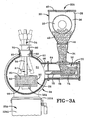
- Furnace 24 is best shown in FIGS. 1 and 3 where it includes a housing 50 that defines a melting environment 51, a vibratory feed chute 52, a plurality of heat sources 54 (such as plasma torches or direct arc electrodes), a hearth 56, and one or more molds 58.
- Housing 50 is an outer shell defining an open furnace area in which the melting occurs in the hearth 56.
- Housing 50 may be of any shape and construction sufficient to provide the necessary atmosphere and space to perform hearth melting, and in the embodiment shown is of a cylindrical multiwalled construction with arcuate ends.
- the housing 50 includes a plurality of heat source mount apertures 60 in a top side thereof, ingot removal ports 62 in the bottom side thereof, and one or more optional view windows 63 (in the embodiment shown in the arcuate ends of the housing although the windows may be positioned anywhere).
- the housing 50 also includes a feed chute extension 64 connected at passage 66 to the melting environment 51.
- the feed chute further including a feed port, preferably in a top surface of the extension where the feeders connect to the chute, where the feed port also includes one or more valves for controlling the flow of titanium chips into the feed chute 52 from the feeders 22.
- Feed chute 52 is movable within the feed chute extension 64 which extends transversely out from an opening in the housing 50, and is configured and designed to allow the feed chute 52 to traverse from wholly within the feed chute extension 64 as shown In FIG. 3 to partially in the feed chute extension and partially within the housing 50 adjacent to the hearth 56 as shown In FIG. 4 and described below in more detail.
- the feed chute 52 includes an open box or hopper 70 with a chute 72 extending therefrom, where the box 70 and chute 72 are positioned on a car 74 that rides on one or more rails 76 within the extension 64.
- the car is of an open top design like a hopper, and the feed port 66 Is positioned such that it aligns over the open top design of the car 70 when the feed chute is fully retracted as shown in FIG. 3 as well as when fully extended as shown in FIG. 4 thereby assuring no spills of titanium chips and other raw materials within the feed chute.
- the feed chute 52 is optimally vibratory to more readily eject the contents thereof via chute 72.
- the vibration acts to work the contents out of the chute.
- the feed chute is further pivotable as best shown in FIG. 5 by arrow F. This allows the chute to be optimally positioned when over the hearth thereby allowing new material to be provided to the hearth in the most optimal position as described below in more detail.
- Each of the plurality of heat source mount apertures 60 allows for a heat source to be positioned within the melting atmosphere or environment 51.
- the heat source mount apertures include a seat 78 against which the heat source 54 is secured.
- Heat source 54 is capable of providing sufficient controlled heat to melt titanium and other similar metals or alloys, and in the embodiment shown, four heat sources are provided as 54A, 54C, 54D, and 54F.
- the various heat sources are used based upon various positive attributes of each including broader plume provided by plasma torch which helps to better break up LDIs, versus with a direct arc electrode an ability to get desired surface finishes, optimal temperature controls, and avoid burning corner and melting crucible.
- plasma torch gives deeper and better stirring than the Industry standard electron beam furnace, while the direct arc electrode gives the deepest and best stirring thereby providing improved metallurgical benefits, better homogeneity, and optimal HDI removal or spinning out due to optimal vortex action or centrifugal forces spinning HDIs into sludge area.
- the heat sources 54A, 54C, 54D, and 54F include a collar 80, a drive 82 and an elongated shaft 84.
- the elongated shaft 84 is driven by the drive 82 to move in a controlled manner in the collar 80 in both an axial direction (extending and retracting within the melting environment to be proximate or away from the hearth) and a pivotal or side to side direction (to pivot in a circular motion or move side to side in a linear motion).
- the drive 82 drives the elongated shaft 84 in an axial direction so as to define a melt position where the heat source extends furthest into the furnace and most proximate the hearth as is shown in FIG.
- the drive 82 also pivots the elongated shaft 84 in a circular movement as shown in FIG. 3 by the arrow A.
- the motion may be limited to side to side linear motion if desirable due to the shape of the area being heated.
- the heat source 54 is a plasma torch whereby a plasma arc Is initiated from the lowermost end of the elongated shaft 84 that extends furthest into the furnace 24.
- Hearth 56 is a primary melt hearth that is circular or elongated with rounded or egg-shaped interior dimensions making it appear similar to a bath tub shape whereby it includes a base 90 and a plurality of side walls 92 and end walls 94 defining an melting cavity 95.
- the hearth 56 is of a water-cooted copper design that is deeper than conventional furnace hearths.
- the hearth is optimally a high conductivity, oxygen free (OFHC) hearth made of copper of a type 120 or 122.
- OFHC oxygen free
- the hearth design is such that the vessel has higher than standard free board due to higher than standard side walls and thus is large enough for a four to six inch skull with two thousand to three thousand pound molten metal capacity and two or more heat sources.
- the melting hearth 56 is preferably mounted on a trunnion 96 to allow for silt ranging from for instance fifteen degree back tilt to one hundred and five degree forward tilt thereby providing a vast array of casting possibilities. Tilting is better than standard overflow techniques as the user controls the flow and timing, and may allow the melting to occur as long as needed to assure LDIs and HDIs are removed or sunk.
- the user thus may control and monitor the "charging" of the molten material, while also avoiding the need for exact mixing as is required in continuous pouring since with tilting all materials may be poured in, mixed and heated for as long as is deemed necessary.
- the heat sources may be slightly decreased to cause the sunken HDIs to become sludge-like and not to be able to flow at all during tilting and/or overflow as described below.
- the hearth includes a pair of overflows 100A and 100B as best shown in FIGS. 6-14 . These overflows channel the molten titanium as it rises into one or more molds as described below based upon rising levels overflowing and/or tilting of the hearth to cause overflow to one side or the other.
- a pair of molds 58A and 58B are shown.
- One mold 58A and 58B is one each side of the hearth and is respectively aligned with the overflows 100A and 100B.
- the molds may be either casting molds to shape the ingot as shown in FIGS. 1-14 where such shapes may be cylinders or slabs, or alternatively may be direct molds shaped identical to the end product.
- the molds are generally of a cylindrical interior contour 111 with an open top 112 and an open bottom 115.
- the open bottom of the molds 58A and 58B receives one of the lift systems 26A or 26B, respectively as described below.
- the ingot removal ports 62A and 62B which align with the molds 58A and 58B and the lift systems 26A and 26B.
- the lift systems 26A and 26B attach to the ingot removal ports to provide for a system to lift direct molds into the melting environment (in contrast, casting molds are affixed in the melting environment) and remove them once filled, or in the case of casting molds to "catch" and remove the ingots as they form within the casting molds.
- the lift system 26A is best shown in FIGS. 1-2 and 6-14 to include an ingot removal chamber 110A with a chamber isolation valve gate mechanism 113A ( Fig. 1 ) and ingot removal door 114A, an ingot removal cylinder 116A, a cylinder housing 118A, and a cylinder drive system 120A.
- ingot removal chamber 110A is an enlarged chamber aligned with the mold 58A such that the ingot as formed is lowered by the cylinder 116A into the chamber 110A as the cylinder is retracted by drive system 120A into housing 118A.
- the chamber 110A is an elongated chamber with an upper end 121A, a lower end 122A, and one or more walls 124A therebetween with one wall including door 114A therein which is removable to remove a completed ingot from the system as described below.
- the chamber isolation valve gate mechanism 113A is positioned in upper end 121A and includes a door 130A embodied as an articulated flapper valve gate, a fixed pivot rod 132A, a first arm 134A, a movable pivot rod 136A, a second arm 138A, a fixed arm 140A with an elongated slot 142A therein, and a slidable pivot rod 144A.
- a drive mechanism on the exterior of the chamber is shown in FIGS. 3-4A .
- Fixed pivot rod 132A is pivotally connected to a first end of first arm 134A and the chamber 110A to allow the first arm 134A to pivot therefrom. Also connected to the first arm 134A is the valve gate 130A.
- a second end of first arm 134A and a first end of second arm 138A are pivotally connected by movable pivot rod 136A.
- a second end of the second arm 138A is slidably connected in slot 142A of fixed arm 140A by slidable pivot rod 144A.
- Slidable pivot rod 144A is connectable to a drive device to allow for automatic opening and closing of the valve gate to correspond to insertion and removal of the cylinder 116A as needed to receive ingots as produced.
- the valve gate mechanism is designed such that it remains out of potential contact with the ingot
- Cylinder 116A slides through the chamber 110A from a fully extended position where the cylinder is fully extended from the housing 198A, through a bushing 146A in a cylinder port 148A, through the chamber 110A, through the ingot removal port 62 and into the melting environment 51 and specifically open bottom 115A, to a fully retracted position where the cylinder is fully retracted into the housing 118A whereby only the cylinder head 117A remains extended through bushing 146A in chamber 110A.
- Drive system 120A as best shown in FIG. 2 includes a threaded drive rod 150A, a guide rod 152A, a trolley or follower 154A and a drive mechanism 156A, all of which is supported by housing 118A.
- Cylinder 116A includes an elongated axial passageway 158A that is threaded at least at each end via a guide plate 160A to mate with the threaded drive rod 150A, and may further include a coolant passage 162A therein also.
- a threaded stop 164A threaded onto the drive rod 150A supports the cylinder 116A and interacts with the trolley 154A as the drive rod 150A is turned to cause axial motion of the cylinder 116A along the drive rod whereby the trolley is slidably coupled to the guide rod 150A assuring a smooth axial motion.
- Drive mechanism 156A includes a drive motor or like device 170A connected to a drive arm 172A that is connected to a non-threaded end 174A of the threaded drive rod 150A extending out of the housing 118A via a bushing 176A.
- the drive motor 170A imparts motion to the arm 172A, which in turn imparts motion to the rod 150A in a mariner well known to those of skill in the art.
- FIGS. 6-14 When it is desirable to make elongated ingots this system is employed whereby heat sources 54C and 54D are lowered to proper positions above the hearth 56 as shown in FIG. 6 whereby this is accomplished by drive 82 lowering elongated shaft 84 within collar 80, and then igniting the lowermost or ignition point of each shaft 84 as shown to provide heat to the interior of the hearth 56 to melt the titanium and alloys therein as well as any added by chute 72 (none being added at this time in the embodiment shown in FIG. 6 ).
- the heat sources 54A and 54F are provided as supplemental heat in this hot top process to control the solidification rate and refine the grain structure. These heat sources also prevent piping, which is common in direct mold casting processes.
- valve gate 130A (associated with the left side lift system) is opened by the motion shown by arrow B.
- slidable pivot rod 144A Is driven by user action or by a drive motor and linkage (shown in FIGS. 3-4A ) to slide downward in the slot 142A of arm 140A.
- This causes arm 138A to pull arm 134A about pivot rod 136A and pivot rod 132A such that the door 130A uncovers Ingot removal port 62A and moves as shown by arrow B.
- Cylinder 116A is then actuated upward as shown by arrow C from its fully retracted position to its fully extended position as shown in FIG. 6 by drive 156A threadably moving trolley 154A up the threaded shaft 150A causing cylinder 116A to be forced upward.
- Heat source 54A is lowered into position as shown by arrow D.
- Chute 72 is moved to its fully extended position. It is preferred that the entry of titanium and like chips be away from the active overflow, in this case 100A (this is shown in FIGS. 7 and 9 with the chute facing right). This is achieved by movement of the chute from side to side as best shown In FIG. 5 by arrow F to best position the chute away from the current open overflow.
- the heat sources 54C and 54D associated with the hearth are rotated as best shown in FIG. 5 by arrows G and H during the entire process, although alternatively the heat sources may be moved side to side or in any other desirable manner.
- the heat sources 54A and 54F may also be rotated or moved side to side or otherwise moved to promote more even melting, and this is shown in FIG. 5 where heat source 54A rotates circularly as shown by arrow I and heat source 54F rotates side to side in a linear fashion as shown by arrows J.
- a full ingot is eventually formed.
- the heat source 54A is shut off and withdrawn as shown by arrow K in FIG. 11 .
- the cylinder 116A is fully withdrawn as shown by arrow L such that the ingot is fully within chamber 110A.
- valve gate 130A is closed and door 114A is opened.
- the chute 72 may also be withdrawn to a fully retracted position.
- valve gate 130B (associated with the right side lift system) is opened by the motion shown by arrow M in the same manner as described above for valve gate 130B on the left side.
- Cylinder 116B on the right side is then actuated upward as shown by arrow N from its fully retracted position to its fully extended position as shown in FIG. 11 in the same manner as described above for the left side cylinder.
- Heat source 54F is lowered into position as shown by arrow O.
- the system setup is thus such that setup is occurring as to one lift system while an ingot is being produced In relation to the other lift system, and vice versa, such that continuous melting and ingot production may occur if desired.
- This is continued in FIG. 12 where an ingot is being removed from the left side, while the right side heat source 54F is ignited thereby causing the titanium in overflow 100B to flow.
- This flow pours molten titanium into casting mold 58B whereby the ingot begins to form therein between the cylinder head 117B and the mold casting interior.
- Cylinder 116B is slowly withdrawn as shown by arrow P in FIG. 13 as additional molten material is added and the elongated ingot forms (this is shown by the transition from FIG. 12 to FIG. 13 ).
- chute 72 additional titanium and other alloy chips may be added as shown by chute 72. It is preferred that the entry be away from the overflow 100B that Is active (this is shown in FIGS. 12 and 13 with the chute facing left). This Is achieved by movement of the chute from side to side as best shown in FIG. 5 by arrow F to best position the chute away from the current open overflow.
- a full ingot is eventually formed.
- the heat source 54F is shut off and withdrawn as shown by arrow Q in FIG. 14 .
- the cylinder 116B is fully withdrawn such that the ingot is fully within chamber 110B.
- valve gate 130B is closed as shown by arrow R and door 114B is opened.
- the chute is moved to a center position (rather than right position and may also be withdrawn to a fully retracted position) and flow is stopped. The ingot will then be removed.
- valve gate 130A is opened by the motion shown by arrow S in the same manner as described above.
- Cylinder 116A on the right side is then actuated upward as shown by arrow T from its fully retracted position to its fully extended position as shown in FIG. 14 in the same manner as described above.
- Heat source 54A is lowered into position as shown by arrow U. The process continues going back and forth as long as desired.
- all four heat sources 54A, 54C, 54D and 54 F may be ignited to allow for flow out of both overflows 100A and 100B resulting in simultaneous ingot production in both molds 58A and 58B.
- pouring may be induced by tilting of the hearth 56 in combination with ignition of the heat source adjacent to the mold, in the case of mold 58A that is heat source 54A. It is also contemplated that ignition of the heat source adjacent the mold may not be necessary to cause overflow during tilting or without tilting should the heat sources associated with the hearth be positioned so as to properly heat the overflow.
- FIGS. 15 , 15A and 16 The embodiment shown in FIGS. 15 , 15A and 16 and is substantially identical to the embodiment shown in Figs. 1-14 except instead of casting molds 58 as described above the embodiment includes direct molds 258A and 258B. These molds are designed to have the contours of a desired end product The molds 258 sit directly on top of the cylinders. In addition, the hearth 56 tips to pour the molten material into the molds as is shown in FIG. 15 . The hearth tips and fills the mold to the desired fill level, and then the hearth returns to its initial level position.
- heat sources 54A and 54F are plasma torches, while heat sources 54C and 54D are direct arc electrodes (DAE).
- DAE direct arc electrodes
- the direct arc electrodes are non-consumable, rotating or fixed, direct arc electrodes.
- FIG. 15 shows heat sources 54A, 54C and 54D ignited causing flow to overflow 100A.
- the cylinder 198A is raised as shown by arrow V such that the direct mold 258A is properly positioned within the melting environment 51.
- the hearth is tipped to the left as shown by arrow W causing pouring into direct mold 258A.
- the other side is shown with the cylinder 116B retracted with mold 258B set thereon, and with the valve gate 130B dosed.
- FIG. 16 shows the system where torch 54A has been shut off and retracted as shown by arrow X, the cylinder 116A removed and fully retracted, valve gate 130A closed as shown by arrow Y, and direct mold 258A removed, while substantially simultaneously therewith valve gate 130B is opened as shown by arrow Z, cylinder 116B is fully extended (arrow AA) into the melting environment with direct mold 258B thereon, heat source 54F is lowered (arrow BB) into melt position and ignited, and hearth 56 is tilted as shown by arrow CC.
- a combination of plasma torches and direct arc electrodes are used as heat sources.
- This mixture combines the benefits of the systems, and offsets the detriments to provide the most advanced cold hearth melting.
- direct arc electrodes and plasma torches may be used in any combination over the melting hearth, refining hearths and molds except that plasma torches are not preferred in the melting hearth as this often introduces the issue of plume winds blowing unmelted solids downstream into the refining hearth and/or molds.
- Plasma cold hearth melting has certain strengths over electron beam cold hearth melting. These include: (1) less expensive equipment costs as plasma cold hearth melting does not require a "hard” vacuum, and the plasma torches are less expensive than electron beam guns or torches, (2) better chemistry consistency using a plasma torch because the operator has better control of the alloys and in particular those alloys containing aluminum as a result of the vacuum used in electron beam melting far exceeding the vapor pressure point of aluminum (resulting in evaporation of elemental aluminum results in potential alloy inconsistency and furnace interior sidewall contamination), (3) no risk of spontaneous combustion in plasma melting versus in electron beam melting where when the melt campaign is completed, and before the chamber door is opened, water is introduced into the chamber to help pacify the metal condensate with a controlled bum under vacuum to avoid the possibility of spontaneous combustion of the dust when the chamber is opened to atmosphere, (4) not exceeding the vapor pressure point of any element used In the manufacture of any known grade of titanium, (5) more accurate chemistry control because evaporation due to differing shaped and sized feed materials
- Electron beam melting has certain strengths over plasma cold hearth melting. These include: (1) very effective means of melting large volumes of commercially pure titanium very cost effectively, (2) better surface finish control as the electron beam is much narrower than a plasma plume and therefore the energy emitted can be controlled more accurately at the crucible wall to produce a better "as cast” surface finish alleviating some of the need to machine material from the surface of the cast product prior to further downstream processing and alleviating some concern associated with burning the copper crucible wall surface.
- the current invention in its most preferred embodiment, combines the benefits of the plasma torches and electron beams by placing direct arc electrodes 54C and 54D in the main hearth with plasma torches 54A, 54B, 54E and 54F in the refining hearths and molds.
- the main hearth torches may be 600kW direct arc electrodes or 900kW plasma torches, and one or multiple may be used, while the refining torches are single 900kW plasma torches, or multiple torches of the same or a different type. In general, low voltage and high current is desired.
- the most preferred embodiment includes torches 54 that move in either a circular or rotational motion as shown by arrows A, G H and/or I, or a linear side to side motion as shown by arrows J, DD, EE, OO and PP. This allows more even and consistent melting and mixing prior to pouring out of the hearth. This also assists in preventing build-up in one place in the skull within the hearth.
- the chute 72 (best shown in FIG. 5 ) is moveable in and out from a fully extended to a fully retracted position as well as from a rightmost position as shown in FIG. 7 for instance to a leftmost position as shown in FIG. 12 for instance, and including a center position as shown in FIG. 11 for instance.
- This allows for best placement of the raw material to allow the material sufficient time to properly melt and mix prior to pouring out of the hearth. This also assists in preventing build-up in one place in the skull within the hearth.
- the invention thus provides and/or improves many advantages, and/or eliminates disadvantages, including but not limited to the following: (1) chemistry variations inherent in continuous melting, (2) surface finish problems, (3) unmelted machine turnings metallics contained in the product due to excessive plume winds in the melting vessel, (4) excessive inert gas use, (5) active rather than passive inclusion removal, (6) greater general versatility (can be operated in a continuous or batch configuration), (7) homogeneous mixing, (8) restrictions on feed stock size and high feed stock preparation costs, (9) super heating, (10) heat management issues, (11) the inability to effectively cast near net shape, small diameter products effectively by traditional means, (12) controlled casting rates via hearth tilting and use of alternating refining hearths and/or molds, (13) continuous casting, and (14) stationary or tilting operations of hearth.
- the system also allows for the re-use of turnings, particularly in the area of non-critical commercial grade alloy and cp titanium.
- the many new commercial uses such as golf club heads that are not critical components where failure is catastrophic (versus aircraft use where it is) increase the ability to use these turnings.
- the unique nature of this invention allows for turnings to be used whereby inclusions are prohibited, eliminated and/or reduced by the design.
- the embodiments described above are described for titanium ingot manufacture.
- the system may also be used for noble metals and high alloy steel and nickel based alloys. Accordingly, the improved cold hearth melting system of the above embodiments is simplified, provides an effective, safe, inexpensive, and efficient device which achieves all the enumerated objectives, provides for eliminating difficulties encountered with prior devices, and solves problems and obtains new results in the art.
Landscapes
- Engineering & Computer Science (AREA)
- Mechanical Engineering (AREA)
- General Engineering & Computer Science (AREA)
- Chemical & Material Sciences (AREA)
- Organic Chemistry (AREA)
- Metallurgy (AREA)
- Materials Engineering (AREA)
- Manufacturing & Machinery (AREA)
- Environmental & Geological Engineering (AREA)
- Geology (AREA)
- General Life Sciences & Earth Sciences (AREA)
- Life Sciences & Earth Sciences (AREA)
- Physics & Mathematics (AREA)
- Plasma & Fusion (AREA)
- Manufacture And Refinement Of Metals (AREA)
- Vertical, Hearth, Or Arc Furnaces (AREA)
Claims (17)
- Vorrichtung zum optimalen Schmelzen von Metall und Metalllegierungen, umfassend:einen Hauptherd, der einen Schmelzhohlraum mit zumindest einem Überlauf ausbildet;zumindest, eine Form, die entsprechend zum Überlauf ausgerichtet ist, und mit ihm in Strömungsmittelverbindung steht;mindestens eine nicht-verzehrbare Direktlichtbogenelektrode zum selektiven Erwärmen;mindestens eine Plasmafackel zum selektiven Erwärmen; undwobei die zumindest eine Direktlichtbogenelektrode und die zumindest eine Plasmafackel zum Erwärmen innerhalb einer einzigen Kammer angeordnet sind, und wobei der Herd und die zumindest eine Form innerhalb der Kammer während des Erwärmens angeordnet sind.
- Vorrichtung nach Anspruch 1, dadurch gekennzeichnet, dass die mindestens eine Form eine erste Form umfasst, angrenzend an ein erstes Ende des Hauptherdes und ausgerichtet zu einem ersten mindestens einen Überfluss umfassenden Hauptherd und eine zweite Form, angrenzend an ein zweites Ende des Hauptherdes und ausgerichtet zu einem zweiten Überfluss des mindestens einen Überfluss umfassenden Hauptherdes.
- Vorrichtung nach Anspruch 1, dadurch gekennzeichnet, dass die mindestens eine Direktlichtbogenelektrode eine erste Direktlichtbogenelektrode oberhalb des Hauptherdes zum selektiven Erwärmen der Inhalte des Hauptherdes umfasst.
- Vorrichtung nach Anspruch 3, dadurch gekennzeichnet, dass die mindestens eine Plasmafackel eine erste Plasmafackel umfasst, oberhalb der mindestens einen Form zum selektiven Erwärmen der Inhalte der mindestens einen Form umfasst.
- Vorrichtung nach Anspruch 1, dadurch gekennzeichnet, dass die mindestens eine Plasmafackel eine Plasmafackel umfasst, oberhalb der mindestens einen Form zum selektiven Erwärmen der Inhalte der mindestens einen Form umfasst.
- Vorrichtung nach Anspruch 2, dadurch gekennzeichnet, dass die mindestens eine Direktlichtbogenelektrode eine erste und eine zweite Direktlichtbogenelektrode, oberhalb des Hauptherdes zum selektiven Erwärmen der Inhalte des Hauptherdes umfasst.
- Vorrichtung nach Anspruch 6, dadurch gekennzeichnet, dass die mindestens eine Plasmafackel eine erste Plasmafackel, oberhalb der ersten Form zum selektiven Erwärmen der Inhalte der ersten Form, und eine zweite Plasmafackel oberhalb der zweiten Form zum selektiven Erwärmen der Inhalte der zweiten Form umfasst.
- Vorrichtung nach Anspruch 7, dadurch gekennzeichnet, dass jede Direktlichtbogenelektrode ausfahrbar in und zurückziehbar aus der Nähe des Hauptherdes ist, und wobei jede der ersten und zweiten Plasmafackeln entsprechend ausfahrbar in und zurückziehbar aus der Nähe der ersten und zweiten Formen ist.
- Vorrichtung nach Anspruch 7, dadurch gekennzeichnet, dass mindestens eine der Direktlichtbogenelektroden in einer kreisförmigen Weise schwenkbar ist, so dass sich ihr eines Zündungsende während der Zündung auf einem Kreis bewegt.
- Vorrichtung nach Anspruch 7, dadurch gekennzeichnet, dass mindestens eine der Direktlichtbogenelektroden und Plasmafackeln derart von einer Seite zur anderen Seite beweglich ist, dass ihr eines Zündungsende linear während der Zündung vor und zurück bewegt.
- Vorrichtung nach Anspruch 1, dadurch gekennzeichnet, dass das Metall und die Metalllegierungen, die geschmolzen werden, Titan und Titanlegierungen umfassen.
- Vorrichtung nach Anspruch 1, dadurch gekennzeichnet, dass zumindest eine Plasmafackel eine erste Plasmafackel, oberhalb des Hauptherdes zum selektiven Erwärmen der Inhalte des Hauptherdes umfasst.
- Vorrichtung nach Anspruch 1, dadurch gekennzeichnet, dass die zumindest eine Direktlichtbogenelektrode eine erste Direktlichtbogenelektrode, oberhalb der mindestens einen Form zum selektiven Erwärmen der Inhalte der Form umfasst.
- Verfahren zum optimalen Schmelzen von Metall und Metalllegierungen, umfassend:Entzünden zumindest einer nicht-verzehrbaren Direktlichtbogenelektrode;Entzünden zumindest einer Plasmafackel;Erwärmen des geschmolzenen Materials mit der zumindest einen Direktlichtbogenelektrode und der mindestens einen Plasmafackel innerhalb einer einzigen Kammer, in der der Hauptherd, und die mindestens eine Form während des Erwärmens angeordnet sind und Gießen des geschmolzenen Materials aus dem Hauptherd in mindestens eine Form, um einen Formkörper auszubilden.
- Verfahren nach Anspruch 14, ferner umfassend das Entzünden mindestens einer Plasmafackel angrenzend an die mindestens eine Form unter Erwärmung des darin geschmolzenen Materials.
- Verfahren nach Anspruch 15, ferner umfassend das Ausfahren und Zurückziehen mindestens einer der Direktlichtbogenelektroden und der Plasmafackeln in und aus der Nähe des mindestens einen Herdes und der Form heraus.
- Verfahren nach Anspruch 15, ferner umfassend das Schwenken in einer kreisförmigen Weise oder das Bewegen mindestens einer der Direktlichtbogenelektrode und Plasmafackel von einer Seite zur anderen.
Applications Claiming Priority (3)
| Application Number | Priority Date | Filing Date | Title |
|---|---|---|---|
| US10/251,030 US6868896B2 (en) | 2002-09-20 | 2002-09-20 | Method and apparatus for melting titanium using a combination of plasma torches and direct arc electrodes |
| US251030 | 2002-09-20 | ||
| PCT/US2003/029658 WO2004058431A2 (en) | 2002-09-20 | 2003-09-19 | Method and apparatus for melting titanium using a combination of plasma torches and direct arc electrodes |
Publications (3)
| Publication Number | Publication Date |
|---|---|
| EP1539399A2 EP1539399A2 (de) | 2005-06-15 |
| EP1539399A4 EP1539399A4 (de) | 2006-06-07 |
| EP1539399B1 true EP1539399B1 (de) | 2009-11-11 |
Family
ID=31992632
Family Applications (1)
| Application Number | Title | Priority Date | Filing Date |
|---|---|---|---|
| EP03811656A Expired - Lifetime EP1539399B1 (de) | 2002-09-20 | 2003-09-19 | Verfahren und vorrichtung zum schmelzen von titan unter verwendung einer kombination aus plasmafackeln und direktlichtbogenelektroden |
Country Status (7)
| Country | Link |
|---|---|
| US (4) | US6868896B2 (de) |
| EP (1) | EP1539399B1 (de) |
| AT (1) | ATE448038T1 (de) |
| AU (1) | AU2003302726A1 (de) |
| BR (1) | BR0306453B1 (de) |
| DE (1) | DE60330020D1 (de) |
| WO (1) | WO2004058431A2 (de) |
Families Citing this family (32)
| Publication number | Priority date | Publication date | Assignee | Title |
|---|---|---|---|---|
| US6868896B2 (en) * | 2002-09-20 | 2005-03-22 | Edward Scott Jackson | Method and apparatus for melting titanium using a combination of plasma torches and direct arc electrodes |
| US6904955B2 (en) * | 2002-09-20 | 2005-06-14 | Lectrotherm, Inc. | Method and apparatus for alternating pouring from common hearth in plasma furnace |
| US7926548B2 (en) * | 2004-11-16 | 2011-04-19 | Rti International Metals, Inc. | Method and apparatus for sealing an ingot at initial startup |
| US7484549B2 (en) * | 2004-11-16 | 2009-02-03 | Rmi Titanium Company | Continuous casting of reactionary metals using a glass covering |
| US7322397B2 (en) * | 2004-11-16 | 2008-01-29 | Rmi Titanium Company | Continuous casting of reactionary metals using a glass covering |
| US7484548B2 (en) * | 2004-11-16 | 2009-02-03 | Rmi Titanium Company | Continuous casting of reactionary metals using a glass covering |
| US8196641B2 (en) | 2004-11-16 | 2012-06-12 | Rti International Metals, Inc. | Continuous casting sealing method |
| US20070256807A1 (en) * | 2006-05-02 | 2007-11-08 | Taiwan Advanced Materials Technologies Corporation | Continuous casting apparatus |
| TW201019480A (en) * | 2008-08-27 | 2010-05-16 | Bp Corp North America Inc | High temperature support apparatus and method of use for casting materials |
| RU2403120C2 (ru) * | 2009-02-09 | 2010-11-10 | Открытое Акционерное Общество "Корпорация Всмпо-Ависма" | Установка для получения литых металлических заготовок |
| AU2010211605A1 (en) | 2009-02-09 | 2011-08-25 | Toho Titanium Co., Ltd. | Titanium slab for hot rolling produced by electron-beam melting furnace, process for production thereof, and process for rolling titanium slab for hot rolling |
| RU2392685C1 (ru) * | 2009-07-17 | 2010-06-20 | Вадим Георгиевич Глебовский | Распыляемые мишени из высокочистых сплавов на основе переходных металлов и способ их производства |
| RU2392686C1 (ru) * | 2009-07-17 | 2010-06-20 | Вадим Георгиевич Глебовский | Составная мишень для распыления и способ ее получения |
| EA029080B1 (ru) * | 2011-02-25 | 2018-02-28 | Тохо Титаниум Ко., Лтд. | Плавильная печь для производства металла |
| US11150021B2 (en) * | 2011-04-07 | 2021-10-19 | Ati Properties Llc | Systems and methods for casting metallic materials |
| JP5774419B2 (ja) * | 2011-09-02 | 2015-09-09 | 株式会社神戸製鋼所 | チタンまたはチタン合金からなるスラブの連続鋳造装置 |
| DE112013006290B4 (de) | 2012-12-28 | 2018-08-02 | Kabushiki Kaisha Kobe Seiko Sho (Kobe Steel, Ltd.) | Kontinuierliche Titan-Gießvorrichtung |
| JP6381868B2 (ja) * | 2013-01-25 | 2018-08-29 | 株式会社神戸製鋼所 | チタンまたはチタン合金からなる鋳塊の連続鋳造方法 |
| US9050650B2 (en) | 2013-02-05 | 2015-06-09 | Ati Properties, Inc. | Tapered hearth |
| US9840755B2 (en) * | 2013-03-18 | 2017-12-12 | Korea Institute Of Industrial Technology | Refining device and refining method for titanium scraps and sponge titanium using deoxidising gas |
| EP3046699B1 (de) * | 2013-10-15 | 2018-08-22 | Retech Systems LLC | System und verfahren zum herstellen eines festen gusskörpers |
| JP6279963B2 (ja) | 2014-04-15 | 2018-02-14 | 株式会社神戸製鋼所 | チタンまたはチタン合金からなるスラブの連続鋳造装置 |
| US9925591B2 (en) | 2014-08-21 | 2018-03-27 | Molyworks Materials Corp. | Mixing cold hearth metallurgical system and process for producing metals and metal alloys |
| JP5703414B1 (ja) * | 2014-09-10 | 2015-04-22 | 石福金属興業株式会社 | 白金族基合金の製造方法 |
| JP6611331B2 (ja) * | 2016-01-07 | 2019-11-27 | 株式会社神戸製鋼所 | チタンまたはチタン合金からなるスラブの連続鋳造方法 |
| US20180277857A1 (en) * | 2017-03-21 | 2018-09-27 | Apollo Energy Systems, Inc. | Method of manufacturing a spongy nickel catalyst and spongy nickel catalyst made thereby |
| US10325743B2 (en) * | 2017-08-04 | 2019-06-18 | Eaton Intelligent Power Limited | Circuit breakers with tamper-evident security seals |
| US10177227B1 (en) | 2017-08-28 | 2019-01-08 | Applied Materials, Inc. | Method for fabricating junctions and spacers for horizontal gate all around devices |
| CN108788040B (zh) * | 2018-07-04 | 2019-07-19 | 上海大学 | 一种氢等离子熔炼连续铸造生产高纯金属靶坯的装置 |
| CN110423918B (zh) * | 2019-08-01 | 2020-09-29 | 大连理工大学 | 一种电子束诱导精炼浇铸技术制备高纯镍基高温合金的方法 |
| US12259185B2 (en) * | 2020-11-04 | 2025-03-25 | Continuum Powders Corporation | Powder feeder system and method for recycling metal powder |
| WO2023076642A1 (en) * | 2021-10-29 | 2023-05-04 | MolyWorks Materials Corporation | Tilting melting hearth system and method for recycling metal |
Family Cites Families (27)
| Publication number | Priority date | Publication date | Assignee | Title |
|---|---|---|---|---|
| US2772455A (en) * | 1955-10-28 | 1956-12-04 | Allegheny Ludlum Steel | Metal pouring apparatus for continuous casting |
| US3273212A (en) * | 1959-01-16 | 1966-09-20 | Republic Steel Corp | Method of operating an electric furnace |
| NL266640A (de) * | 1960-08-01 | 1900-01-01 | ||
| US3258328A (en) * | 1962-08-23 | 1966-06-28 | Fuji Iron & Steel Co Ltd | Method and apparatus for treating steel |
| US4027722A (en) * | 1963-02-01 | 1977-06-07 | Airco, Inc. | Electron beam furnace |
| DE1291760B (de) * | 1963-11-08 | 1969-04-03 | Suedwestfalen Ag Stahlwerke | Verfahren und Vorrichtung zum diskontinuierlichen und kontinuierlichen Vakuum-Schmelzen und -Giessen von Staehlen und stahlaehnlichen Legierungen (Superiegierungen) |
| US3651238A (en) * | 1970-07-17 | 1972-03-21 | Max P Schlienger | Arc furnace electrode wheel mounting system |
| GB1338303A (en) * | 1971-06-08 | 1973-11-21 | British Iron Steel Research | Metal refining process |
| US4036568A (en) * | 1973-12-07 | 1977-07-19 | Creusot-Loire | Machines for manufacture of powders |
| US4017722A (en) * | 1975-04-11 | 1977-04-12 | Measurex Corporation | Control system for textile tenter frame |
| JPS5841939B2 (ja) * | 1976-12-29 | 1983-09-16 | 大同特殊鋼株式会社 | 加熱装置及び加熱方法 |
| US4371392A (en) * | 1978-12-27 | 1983-02-01 | Daido Tokishuko Kabushiki Kaisha | Process for refining a molten metal |
| US4308415A (en) * | 1978-12-27 | 1981-12-29 | Daido Tokushuko Kabushiki Kaisha | Process for refining a molten metal and an apparatus therefor |
| JPS58100951A (ja) * | 1981-12-09 | 1983-06-15 | Nippon Steel Corp | 連続鋳造用溶鋼の温度調整方法 |
| US4794979A (en) * | 1984-06-15 | 1989-01-03 | Mcdonnell Douglas Corporation | Method for melting metal, particularly scrap, and forming metal billets |
| DE3527628A1 (de) * | 1985-08-01 | 1987-02-05 | Leybold Heraeus Gmbh & Co Kg | Verfahren und vorrichtung zum einschmelzen und umschmelzen von partikelfoermigen metallen zu straengen, insbesondere zu brammen |
| US4718477A (en) * | 1986-07-30 | 1988-01-12 | Plasma Energy Corporation | Apparatus and method for processing reactive metals |
| USRE32932E (en) * | 1987-03-06 | 1989-05-30 | A Johnson Metals Corporation | Cold hearth refining |
| US4878953A (en) * | 1988-01-13 | 1989-11-07 | Metallurgical Industries, Inc. | Method of refurbishing cast gas turbine engine components and refurbished component |
| US5100463A (en) * | 1990-07-19 | 1992-03-31 | Axel Johnson Metals, Inc. | Method of operating an electron beam furnace |
| AT399513B (de) * | 1990-10-05 | 1995-05-26 | Boehler Edelstahl | Verfahren und vorrichtung zur herstellung von metallischen legierungen für vormaterialien, bauteile, werkstücke oder dergleichen aus titan-aluminium-basislegierungen |
| US5132984A (en) * | 1990-11-01 | 1992-07-21 | Norton Company | Segmented electric furnace |
| US5291940A (en) * | 1991-09-13 | 1994-03-08 | Axel Johnson Metals, Inc. | Static vacuum casting of ingots |
| US6379419B1 (en) * | 1998-08-18 | 2002-04-30 | Noranda Inc. | Method and transferred arc plasma system for production of fine and ultrafine powders |
| US6561259B2 (en) * | 2000-12-27 | 2003-05-13 | Rmi Titanium Company | Method of melting titanium and other metals and alloys by plasma arc or electron beam |
| US6712875B1 (en) * | 2002-09-20 | 2004-03-30 | Lectrotherm, Inc. | Method and apparatus for optimized mixing in a common hearth in plasma furnace |
| US6868896B2 (en) * | 2002-09-20 | 2005-03-22 | Edward Scott Jackson | Method and apparatus for melting titanium using a combination of plasma torches and direct arc electrodes |
-
2002
- 2002-09-20 US US10/251,030 patent/US6868896B2/en not_active Expired - Lifetime
-
2003
- 2003-09-19 DE DE60330020T patent/DE60330020D1/de not_active Expired - Lifetime
- 2003-09-19 EP EP03811656A patent/EP1539399B1/de not_active Expired - Lifetime
- 2003-09-19 WO PCT/US2003/029658 patent/WO2004058431A2/en not_active Ceased
- 2003-09-19 BR BRPI0306453-0A patent/BR0306453B1/pt not_active IP Right Cessation
- 2003-09-19 AU AU2003302726A patent/AU2003302726A1/en not_active Abandoned
- 2003-09-19 AT AT03811656T patent/ATE448038T1/de not_active IP Right Cessation
-
2005
- 2005-02-16 US US11/058,796 patent/US7137436B2/en not_active Expired - Fee Related
-
2006
- 2006-09-15 US US11/521,659 patent/US7503376B2/en not_active Expired - Fee Related
- 2006-09-15 US US11/521,648 patent/US7637307B2/en not_active Expired - Lifetime
Also Published As
| Publication number | Publication date |
|---|---|
| AU2003302726A8 (en) | 2004-07-22 |
| US7137436B2 (en) | 2006-11-21 |
| US7637307B2 (en) | 2009-12-29 |
| WO2004058431A8 (en) | 2005-09-15 |
| US20040055733A1 (en) | 2004-03-25 |
| US6868896B2 (en) | 2005-03-22 |
| BR0306453B1 (pt) | 2011-06-28 |
| WO2004058431A3 (en) | 2004-09-23 |
| EP1539399A2 (de) | 2005-06-15 |
| US20070006989A1 (en) | 2007-01-11 |
| AU2003302726A1 (en) | 2004-07-22 |
| DE60330020D1 (de) | 2009-12-24 |
| US7503376B2 (en) | 2009-03-17 |
| WO2004058431A2 (en) | 2004-07-15 |
| ATE448038T1 (de) | 2009-11-15 |
| BR0306453A (pt) | 2004-11-09 |
| US20090256292A1 (en) | 2009-10-15 |
| EP1539399A4 (de) | 2006-06-07 |
| US20050145064A1 (en) | 2005-07-07 |
Similar Documents
| Publication | Publication Date | Title |
|---|---|---|
| EP1539399B1 (de) | Verfahren und vorrichtung zum schmelzen von titan unter verwendung einer kombination aus plasmafackeln und direktlichtbogenelektroden | |
| EP1539400B1 (de) | Verfahren und vorrichtung zum abwechselnden giessen aus einem gemeinsamen gestell in einem plasmaofen | |
| EP1567680B1 (de) | Verfahren und vorrichtung für optimiertes mischen in einem gemeinsamen gestell in einem plasmaofen | |
| RU2089633C1 (ru) | Устройство для плавления и литья металлов и сплавов | |
| US3650311A (en) | Method for homogeneous refining and continuously casting metals and alloys | |
| DE68915496T2 (de) | Vorrichtung zur Herstellung von Metallpulver. | |
| EP0907756B1 (de) | Weiterverarbeitung durch elektroschlackeumschmelzen gereinigter metalle | |
| US5263689A (en) | Apparatus for making alloy power | |
| JP3969739B2 (ja) | 溶融した鋳造耐火物を製造する方法 | |
| KR0161961B1 (ko) | 다용도 제강 용기 및 이를 이용한 제강 방법 | |
| RU2286398C2 (ru) | Способ литья металла с использованием гарнисажа в качестве расходуемого электрода | |
| CN112899491A (zh) | 电炉熔炼异质锭的方法 | |
| US4552587A (en) | Method of operating ladle refining furnace | |
| CN114273634A (zh) | 消除压铸件螺纹孔缺陷的生产方法 | |
| EP0542825A4 (de) | ||
| JPH0421727A (ja) | チタン鋳塊の製造方法および装置 | |
| RU2032754C1 (ru) | Способ производства вальца | |
| CN117701897A (zh) | 一种k465等轴高温合金返回料的超纯熔炼方法 | |
| CN121450941A (zh) | 一种自动给料的电弧加热预制熔铸的设备及方法 | |
| Chandley | Quality enhancement by fluid flow control in counter gravity casting processes | |
| JPH0957400A (ja) | 溶解鋳造装置 | |
| Borofka | Electron Beam Cold Hearth Refining of Investment Casting Superalloys in a Large Production EB Furnace | |
| Kanai | Present features and future prospects in titanium melting and casting | |
| CS276483B6 (cs) | Způsob výroby slitin mědi s kovy o vysoké teplotě táni |
Legal Events
| Date | Code | Title | Description |
|---|---|---|---|
| PUAI | Public reference made under article 153(3) epc to a published international application that has entered the european phase |
Free format text: ORIGINAL CODE: 0009012 |
|
| 17P | Request for examination filed |
Effective date: 20050412 |
|
| AK | Designated contracting states |
Kind code of ref document: A2 Designated state(s): AT BE BG CH CY CZ DE DK EE ES FI FR GB GR HU IE IT LI LU MC NL PT RO SE SI SK TR |
|
| AX | Request for extension of the european patent |
Extension state: AL LT LV MK |
|
| RIC1 | Information provided on ipc code assigned before grant |
Ipc: 7B 22D 11/10 A |
|
| DAX | Request for extension of the european patent (deleted) | ||
| A4 | Supplementary search report drawn up and despatched |
Effective date: 20060425 |
|
| 17Q | First examination report despatched |
Effective date: 20071008 |
|
| RAP1 | Party data changed (applicant data changed or rights of an application transferred) |
Owner name: AJAX TOCCO MAGNETHERMIC CORPORATION |
|
| GRAP | Despatch of communication of intention to grant a patent |
Free format text: ORIGINAL CODE: EPIDOSNIGR1 |
|
| GRAS | Grant fee paid |
Free format text: ORIGINAL CODE: EPIDOSNIGR3 |
|
| GRAA | (expected) grant |
Free format text: ORIGINAL CODE: 0009210 |
|
| AK | Designated contracting states |
Kind code of ref document: B1 Designated state(s): AT BE BG CH CY CZ DE DK EE ES FI FR GB GR HU IE IT LI LU MC NL PT RO SE SI SK TR |
|
| REG | Reference to a national code |
Ref country code: GB Ref legal event code: FG4D |
|
| REG | Reference to a national code |
Ref country code: CH Ref legal event code: EP |
|
| REG | Reference to a national code |
Ref country code: IE Ref legal event code: FG4D |
|
| REF | Corresponds to: |
Ref document number: 60330020 Country of ref document: DE Date of ref document: 20091224 Kind code of ref document: P |
|
| NLV1 | Nl: lapsed or annulled due to failure to fulfill the requirements of art. 29p and 29m of the patents act | ||
| PG25 | Lapsed in a contracting state [announced via postgrant information from national office to epo] |
Ref country code: PT Free format text: LAPSE BECAUSE OF FAILURE TO SUBMIT A TRANSLATION OF THE DESCRIPTION OR TO PAY THE FEE WITHIN THE PRESCRIBED TIME-LIMIT Effective date: 20100311 Ref country code: ES Free format text: LAPSE BECAUSE OF FAILURE TO SUBMIT A TRANSLATION OF THE DESCRIPTION OR TO PAY THE FEE WITHIN THE PRESCRIBED TIME-LIMIT Effective date: 20100222 Ref country code: SE Free format text: LAPSE BECAUSE OF FAILURE TO SUBMIT A TRANSLATION OF THE DESCRIPTION OR TO PAY THE FEE WITHIN THE PRESCRIBED TIME-LIMIT Effective date: 20091111 Ref country code: FI Free format text: LAPSE BECAUSE OF FAILURE TO SUBMIT A TRANSLATION OF THE DESCRIPTION OR TO PAY THE FEE WITHIN THE PRESCRIBED TIME-LIMIT Effective date: 20091111 |
|
| PG25 | Lapsed in a contracting state [announced via postgrant information from national office to epo] |
Ref country code: CY Free format text: LAPSE BECAUSE OF FAILURE TO SUBMIT A TRANSLATION OF THE DESCRIPTION OR TO PAY THE FEE WITHIN THE PRESCRIBED TIME-LIMIT Effective date: 20091111 Ref country code: SI Free format text: LAPSE BECAUSE OF FAILURE TO SUBMIT A TRANSLATION OF THE DESCRIPTION OR TO PAY THE FEE WITHIN THE PRESCRIBED TIME-LIMIT Effective date: 20091111 |
|
| PG25 | Lapsed in a contracting state [announced via postgrant information from national office to epo] |
Ref country code: AT Free format text: LAPSE BECAUSE OF FAILURE TO SUBMIT A TRANSLATION OF THE DESCRIPTION OR TO PAY THE FEE WITHIN THE PRESCRIBED TIME-LIMIT Effective date: 20091111 |
|
| PG25 | Lapsed in a contracting state [announced via postgrant information from national office to epo] |
Ref country code: BG Free format text: LAPSE BECAUSE OF FAILURE TO SUBMIT A TRANSLATION OF THE DESCRIPTION OR TO PAY THE FEE WITHIN THE PRESCRIBED TIME-LIMIT Effective date: 20100211 Ref country code: EE Free format text: LAPSE BECAUSE OF FAILURE TO SUBMIT A TRANSLATION OF THE DESCRIPTION OR TO PAY THE FEE WITHIN THE PRESCRIBED TIME-LIMIT Effective date: 20091111 Ref country code: DK Free format text: LAPSE BECAUSE OF FAILURE TO SUBMIT A TRANSLATION OF THE DESCRIPTION OR TO PAY THE FEE WITHIN THE PRESCRIBED TIME-LIMIT Effective date: 20091111 Ref country code: RO Free format text: LAPSE BECAUSE OF FAILURE TO SUBMIT A TRANSLATION OF THE DESCRIPTION OR TO PAY THE FEE WITHIN THE PRESCRIBED TIME-LIMIT Effective date: 20091111 |
|
| PG25 | Lapsed in a contracting state [announced via postgrant information from national office to epo] |
Ref country code: SK Free format text: LAPSE BECAUSE OF FAILURE TO SUBMIT A TRANSLATION OF THE DESCRIPTION OR TO PAY THE FEE WITHIN THE PRESCRIBED TIME-LIMIT Effective date: 20091111 Ref country code: CZ Free format text: LAPSE BECAUSE OF FAILURE TO SUBMIT A TRANSLATION OF THE DESCRIPTION OR TO PAY THE FEE WITHIN THE PRESCRIBED TIME-LIMIT Effective date: 20091111 |
|
| PLBE | No opposition filed within time limit |
Free format text: ORIGINAL CODE: 0009261 |
|
| STAA | Information on the status of an ep patent application or granted ep patent |
Free format text: STATUS: NO OPPOSITION FILED WITHIN TIME LIMIT |
|
| 26N | No opposition filed |
Effective date: 20100812 |
|
| PG25 | Lapsed in a contracting state [announced via postgrant information from national office to epo] |
Ref country code: GR Free format text: LAPSE BECAUSE OF FAILURE TO SUBMIT A TRANSLATION OF THE DESCRIPTION OR TO PAY THE FEE WITHIN THE PRESCRIBED TIME-LIMIT Effective date: 20100212 |
|
| PG25 | Lapsed in a contracting state [announced via postgrant information from national office to epo] |
Ref country code: IT Free format text: LAPSE BECAUSE OF FAILURE TO SUBMIT A TRANSLATION OF THE DESCRIPTION OR TO PAY THE FEE WITHIN THE PRESCRIBED TIME-LIMIT Effective date: 20091111 |
|
| PG25 | Lapsed in a contracting state [announced via postgrant information from national office to epo] |
Ref country code: MC Free format text: LAPSE BECAUSE OF NON-PAYMENT OF DUE FEES Effective date: 20100930 |
|
| REG | Reference to a national code |
Ref country code: CH Ref legal event code: PL |
|
| PG25 | Lapsed in a contracting state [announced via postgrant information from national office to epo] |
Ref country code: LI Free format text: LAPSE BECAUSE OF NON-PAYMENT OF DUE FEES Effective date: 20100930 Ref country code: CH Free format text: LAPSE BECAUSE OF NON-PAYMENT OF DUE FEES Effective date: 20100930 Ref country code: IE Free format text: LAPSE BECAUSE OF NON-PAYMENT OF DUE FEES Effective date: 20100919 |
|
| PG25 | Lapsed in a contracting state [announced via postgrant information from national office to epo] |
Ref country code: LU Free format text: LAPSE BECAUSE OF NON-PAYMENT OF DUE FEES Effective date: 20100919 Ref country code: HU Free format text: LAPSE BECAUSE OF FAILURE TO SUBMIT A TRANSLATION OF THE DESCRIPTION OR TO PAY THE FEE WITHIN THE PRESCRIBED TIME-LIMIT Effective date: 20100512 Ref country code: NL Free format text: LAPSE BECAUSE OF FAILURE TO SUBMIT A TRANSLATION OF THE DESCRIPTION OR TO PAY THE FEE WITHIN THE PRESCRIBED TIME-LIMIT Effective date: 20091111 |
|
| PG25 | Lapsed in a contracting state [announced via postgrant information from national office to epo] |
Ref country code: TR Free format text: LAPSE BECAUSE OF FAILURE TO SUBMIT A TRANSLATION OF THE DESCRIPTION OR TO PAY THE FEE WITHIN THE PRESCRIBED TIME-LIMIT Effective date: 20091111 |
|
| REG | Reference to a national code |
Ref country code: FR Ref legal event code: PLFP Year of fee payment: 13 |
|
| REG | Reference to a national code |
Ref country code: DE Ref legal event code: R082 Ref document number: 60330020 Country of ref document: DE Representative=s name: RAFFAY & FLECK PATENTANWAELTE, DE Ref country code: DE Ref legal event code: R081 Ref document number: 60330020 Country of ref document: DE Owner name: RETECH SYSTEMS LLC, UKIAH, US Free format text: FORMER OWNER: AJAX TOCCO MAGNETHERMIC CORP., EUCLID, OHIO, US |
|
| REG | Reference to a national code |
Ref country code: GB Ref legal event code: 732E Free format text: REGISTERED BETWEEN 20150723 AND 20150729 |
|
| PGFP | Annual fee paid to national office [announced via postgrant information from national office to epo] |
Ref country code: GB Payment date: 20150916 Year of fee payment: 13 |
|
| PGFP | Annual fee paid to national office [announced via postgrant information from national office to epo] |
Ref country code: BE Payment date: 20150911 Year of fee payment: 13 Ref country code: FR Payment date: 20150629 Year of fee payment: 13 |
|
| REG | Reference to a national code |
Ref country code: FR Ref legal event code: TP Owner name: RETECH SYSTEMS LLC, US Effective date: 20151231 |
|
| PG25 | Lapsed in a contracting state [announced via postgrant information from national office to epo] |
Ref country code: BE Free format text: LAPSE BECAUSE OF NON-PAYMENT OF DUE FEES Effective date: 20160930 |
|
| GBPC | Gb: european patent ceased through non-payment of renewal fee |
Effective date: 20160919 |
|
| REG | Reference to a national code |
Ref country code: FR Ref legal event code: ST Effective date: 20170531 |
|
| PG25 | Lapsed in a contracting state [announced via postgrant information from national office to epo] |
Ref country code: FR Free format text: LAPSE BECAUSE OF NON-PAYMENT OF DUE FEES Effective date: 20160930 Ref country code: GB Free format text: LAPSE BECAUSE OF NON-PAYMENT OF DUE FEES Effective date: 20160919 |
|
| PGFP | Annual fee paid to national office [announced via postgrant information from national office to epo] |
Ref country code: DE Payment date: 20170912 Year of fee payment: 15 |
|
| REG | Reference to a national code |
Ref country code: BE Ref legal event code: MM Effective date: 20160930 Ref country code: BE Ref legal event code: PD Owner name: RETECH SYSTEMS LLC; US Free format text: DETAILS ASSIGNMENT: CHANGE OF OWNER(S), AFFECTATION / CESSION; FORMER OWNER NAME: AJAX TOCCO MAGNETHERMIC CORPORATION Effective date: 20150827 |
|
| REG | Reference to a national code |
Ref country code: DE Ref legal event code: R119 Ref document number: 60330020 Country of ref document: DE |
|
| PG25 | Lapsed in a contracting state [announced via postgrant information from national office to epo] |
Ref country code: DE Free format text: LAPSE BECAUSE OF NON-PAYMENT OF DUE FEES Effective date: 20190402 |