EP1539037B1 - Medizinisches gerät mit fenster - Google Patents
Medizinisches gerät mit fenster Download PDFInfo
- Publication number
- EP1539037B1 EP1539037B1 EP03754655A EP03754655A EP1539037B1 EP 1539037 B1 EP1539037 B1 EP 1539037B1 EP 03754655 A EP03754655 A EP 03754655A EP 03754655 A EP03754655 A EP 03754655A EP 1539037 B1 EP1539037 B1 EP 1539037B1
- Authority
- EP
- European Patent Office
- Prior art keywords
- medical device
- implantable medical
- framework
- barrier material
- implantable
- Prior art date
- Legal status (The legal status is an assumption and is not a legal conclusion. Google has not performed a legal analysis and makes no representation as to the accuracy of the status listed.)
- Expired - Lifetime
Links
- 239000000463 material Substances 0.000 claims abstract description 120
- 230000004888 barrier function Effects 0.000 claims abstract description 56
- 230000002792 vascular Effects 0.000 claims description 24
- 229920000642 polymer Polymers 0.000 claims description 9
- -1 polytetrafluoroethylene Polymers 0.000 claims description 8
- 230000002093 peripheral effect Effects 0.000 claims description 7
- 229920001343 polytetrafluoroethylene Polymers 0.000 claims description 7
- 239000004810 polytetrafluoroethylene Substances 0.000 claims description 7
- 229910052751 metal Inorganic materials 0.000 claims description 6
- 239000002184 metal Substances 0.000 claims description 6
- 239000000945 filler Substances 0.000 claims description 5
- 229920001971 elastomer Polymers 0.000 claims description 4
- 239000000806 elastomer Substances 0.000 claims description 4
- 229920002313 fluoropolymer Polymers 0.000 claims 6
- 239000004811 fluoropolymer Substances 0.000 claims 6
- 239000012530 fluid Substances 0.000 abstract description 11
- 238000004891 communication Methods 0.000 abstract description 6
- 238000005192 partition Methods 0.000 abstract description 4
- 238000000034 method Methods 0.000 description 17
- 239000010410 layer Substances 0.000 description 14
- 229920000295 expanded polytetrafluoroethylene Polymers 0.000 description 12
- 210000002254 renal artery Anatomy 0.000 description 11
- 208000002223 abdominal aortic aneurysm Diseases 0.000 description 10
- 208000007474 aortic aneurysm Diseases 0.000 description 9
- 238000001356 surgical procedure Methods 0.000 description 8
- 238000013461 design Methods 0.000 description 7
- 239000007943 implant Substances 0.000 description 7
- 238000002513 implantation Methods 0.000 description 7
- 230000015572 biosynthetic process Effects 0.000 description 6
- 239000008280 blood Substances 0.000 description 6
- 210000004369 blood Anatomy 0.000 description 6
- 230000010412 perfusion Effects 0.000 description 6
- 239000004812 Fluorinated ethylene propylene Substances 0.000 description 5
- 239000000853 adhesive Substances 0.000 description 5
- 230000001070 adhesive effect Effects 0.000 description 5
- 210000000709 aorta Anatomy 0.000 description 5
- 229920009441 perflouroethylene propylene Polymers 0.000 description 5
- 229920000544 Gore-Tex Polymers 0.000 description 4
- XEEYBQQBJWHFJM-UHFFFAOYSA-N Iron Chemical compound [Fe] XEEYBQQBJWHFJM-UHFFFAOYSA-N 0.000 description 4
- 238000004873 anchoring Methods 0.000 description 4
- 230000008901 benefit Effects 0.000 description 4
- 239000004621 biodegradable polymer Substances 0.000 description 4
- 238000010276 construction Methods 0.000 description 4
- 208000037265 diseases, disorders, signs and symptoms Diseases 0.000 description 4
- 229940127554 medical product Drugs 0.000 description 4
- 229920002635 polyurethane Polymers 0.000 description 4
- 239000004814 polyurethane Substances 0.000 description 4
- BLTXWCKMNMYXEA-UHFFFAOYSA-N 1,1,2-trifluoro-2-(trifluoromethoxy)ethene Chemical compound FC(F)=C(F)OC(F)(F)F BLTXWCKMNMYXEA-UHFFFAOYSA-N 0.000 description 3
- 206010002329 Aneurysm Diseases 0.000 description 3
- 208000002330 Congenital Heart Defects Diseases 0.000 description 3
- 210000003484 anatomy Anatomy 0.000 description 3
- QVGXLLKOCUKJST-UHFFFAOYSA-N atomic oxygen Chemical compound [O] QVGXLLKOCUKJST-UHFFFAOYSA-N 0.000 description 3
- 201000010099 disease Diseases 0.000 description 3
- 238000005516 engineering process Methods 0.000 description 3
- HQQADJVZYDDRJT-UHFFFAOYSA-N ethene;prop-1-ene Chemical group C=C.CC=C HQQADJVZYDDRJT-UHFFFAOYSA-N 0.000 description 3
- 210000003090 iliac artery Anatomy 0.000 description 3
- 238000004519 manufacturing process Methods 0.000 description 3
- 150000002739 metals Chemical class 0.000 description 3
- 239000000203 mixture Substances 0.000 description 3
- 229910052760 oxygen Inorganic materials 0.000 description 3
- 239000001301 oxygen Substances 0.000 description 3
- 230000002787 reinforcement Effects 0.000 description 3
- BFKJFAAPBSQJPD-UHFFFAOYSA-N tetrafluoroethene Chemical group FC(F)=C(F)F BFKJFAAPBSQJPD-UHFFFAOYSA-N 0.000 description 3
- GVJHHUAWPYXKBD-UHFFFAOYSA-N (±)-α-Tocopherol Chemical compound OC1=C(C)C(C)=C2OC(CCCC(C)CCCC(C)CCCC(C)C)(C)CCC2=C1C GVJHHUAWPYXKBD-UHFFFAOYSA-N 0.000 description 2
- CURLTUGMZLYLDI-UHFFFAOYSA-N Carbon dioxide Chemical compound O=C=O CURLTUGMZLYLDI-UHFFFAOYSA-N 0.000 description 2
- AEMRFAOFKBGASW-UHFFFAOYSA-N Glycolic acid Chemical compound OCC(O)=O AEMRFAOFKBGASW-UHFFFAOYSA-N 0.000 description 2
- 239000004952 Polyamide Substances 0.000 description 2
- 201000008982 Thoracic Aortic Aneurysm Diseases 0.000 description 2
- 229910052782 aluminium Inorganic materials 0.000 description 2
- XAGFODPZIPBFFR-UHFFFAOYSA-N aluminium Chemical compound [Al] XAGFODPZIPBFFR-UHFFFAOYSA-N 0.000 description 2
- 229920002988 biodegradable polymer Polymers 0.000 description 2
- 230000017531 blood circulation Effects 0.000 description 2
- 230000015556 catabolic process Effects 0.000 description 2
- 239000011248 coating agent Substances 0.000 description 2
- 238000000576 coating method Methods 0.000 description 2
- 229920001577 copolymer Polymers 0.000 description 2
- 238000005520 cutting process Methods 0.000 description 2
- 238000006731 degradation reaction Methods 0.000 description 2
- 230000002526 effect on cardiovascular system Effects 0.000 description 2
- 230000005831 heart abnormality Effects 0.000 description 2
- 238000003384 imaging method Methods 0.000 description 2
- 238000011065 in-situ storage Methods 0.000 description 2
- 238000013152 interventional procedure Methods 0.000 description 2
- 229910052742 iron Inorganic materials 0.000 description 2
- 230000003902 lesion Effects 0.000 description 2
- 239000012528 membrane Substances 0.000 description 2
- 229910001092 metal group alloy Inorganic materials 0.000 description 2
- 238000012986 modification Methods 0.000 description 2
- 230000004048 modification Effects 0.000 description 2
- 238000000465 moulding Methods 0.000 description 2
- 229920002647 polyamide Polymers 0.000 description 2
- 229920000728 polyester Polymers 0.000 description 2
- 238000009958 sewing Methods 0.000 description 2
- 238000004513 sizing Methods 0.000 description 2
- 238000005476 soldering Methods 0.000 description 2
- 238000011477 surgical intervention Methods 0.000 description 2
- 238000002560 therapeutic procedure Methods 0.000 description 2
- 210000001519 tissue Anatomy 0.000 description 2
- 208000007340 tricuspid atresia Diseases 0.000 description 2
- 238000012800 visualization Methods 0.000 description 2
- 238000003466 welding Methods 0.000 description 2
- JJTUDXZGHPGLLC-QWWZWVQMSA-N (3r,6r)-3,6-dimethyl-1,4-dioxane-2,5-dione Chemical compound C[C@H]1OC(=O)[C@@H](C)OC1=O JJTUDXZGHPGLLC-QWWZWVQMSA-N 0.000 description 1
- VPVXHAANQNHFSF-UHFFFAOYSA-N 1,4-dioxan-2-one Chemical compound O=C1COCCO1 VPVXHAANQNHFSF-UHFFFAOYSA-N 0.000 description 1
- RKDVKSZUMVYZHH-UHFFFAOYSA-N 1,4-dioxane-2,5-dione Chemical compound O=C1COC(=O)CO1 RKDVKSZUMVYZHH-UHFFFAOYSA-N 0.000 description 1
- 229910000619 316 stainless steel Inorganic materials 0.000 description 1
- SJZRECIVHVDYJC-UHFFFAOYSA-M 4-hydroxybutyrate Chemical compound OCCCC([O-])=O SJZRECIVHVDYJC-UHFFFAOYSA-M 0.000 description 1
- OKTJSMMVPCPJKN-UHFFFAOYSA-N Carbon Chemical compound [C] OKTJSMMVPCPJKN-UHFFFAOYSA-N 0.000 description 1
- VYZAMTAEIAYCRO-UHFFFAOYSA-N Chromium Chemical compound [Cr] VYZAMTAEIAYCRO-UHFFFAOYSA-N 0.000 description 1
- 206010010356 Congenital anomaly Diseases 0.000 description 1
- 229920004934 Dacron® Polymers 0.000 description 1
- 208000005189 Embolism Diseases 0.000 description 1
- 229910052688 Gadolinium Inorganic materials 0.000 description 1
- 239000004677 Nylon Substances 0.000 description 1
- 239000004743 Polypropylene Substances 0.000 description 1
- BQCADISMDOOEFD-UHFFFAOYSA-N Silver Chemical compound [Ag] BQCADISMDOOEFD-UHFFFAOYSA-N 0.000 description 1
- 229930003427 Vitamin E Natural products 0.000 description 1
- 238000002679 ablation Methods 0.000 description 1
- 230000005856 abnormality Effects 0.000 description 1
- 238000010521 absorption reaction Methods 0.000 description 1
- 210000000702 aorta abdominal Anatomy 0.000 description 1
- 238000013459 approach Methods 0.000 description 1
- 229910052788 barium Inorganic materials 0.000 description 1
- DSAJWYNOEDNPEQ-UHFFFAOYSA-N barium atom Chemical compound [Ba] DSAJWYNOEDNPEQ-UHFFFAOYSA-N 0.000 description 1
- 230000008081 blood perfusion Effects 0.000 description 1
- 210000004204 blood vessel Anatomy 0.000 description 1
- 229910002092 carbon dioxide Inorganic materials 0.000 description 1
- 239000001569 carbon dioxide Substances 0.000 description 1
- 230000000747 cardiac effect Effects 0.000 description 1
- 238000007675 cardiac surgery Methods 0.000 description 1
- 238000005266 casting Methods 0.000 description 1
- 229910052804 chromium Inorganic materials 0.000 description 1
- 239000011651 chromium Substances 0.000 description 1
- 230000004087 circulation Effects 0.000 description 1
- 150000001875 compounds Chemical class 0.000 description 1
- 230000006835 compression Effects 0.000 description 1
- 238000007906 compression Methods 0.000 description 1
- 238000000748 compression moulding Methods 0.000 description 1
- 208000028831 congenital heart disease Diseases 0.000 description 1
- 208000029078 coronary artery disease Diseases 0.000 description 1
- 210000004351 coronary vessel Anatomy 0.000 description 1
- 238000012937 correction Methods 0.000 description 1
- 230000007547 defect Effects 0.000 description 1
- 238000011257 definitive treatment Methods 0.000 description 1
- 238000010586 diagram Methods 0.000 description 1
- 238000006073 displacement reaction Methods 0.000 description 1
- 230000000694 effects Effects 0.000 description 1
- 238000009760 electrical discharge machining Methods 0.000 description 1
- 230000002708 enhancing effect Effects 0.000 description 1
- 230000007717 exclusion Effects 0.000 description 1
- 229920001973 fluoroelastomer Polymers 0.000 description 1
- 238000002594 fluoroscopy Methods 0.000 description 1
- UIWYJDYFSGRHKR-UHFFFAOYSA-N gadolinium atom Chemical compound [Gd] UIWYJDYFSGRHKR-UHFFFAOYSA-N 0.000 description 1
- WIGCFUFOHFEKBI-UHFFFAOYSA-N gamma-tocopherol Natural products CC(C)CCCC(C)CCCC(C)CCCC1CCC2C(C)C(O)C(C)C(C)C2O1 WIGCFUFOHFEKBI-UHFFFAOYSA-N 0.000 description 1
- PCHJSUWPFVWCPO-UHFFFAOYSA-N gold Chemical compound [Au] PCHJSUWPFVWCPO-UHFFFAOYSA-N 0.000 description 1
- 229910052737 gold Inorganic materials 0.000 description 1
- 239000010931 gold Substances 0.000 description 1
- 229910002804 graphite Inorganic materials 0.000 description 1
- 239000010439 graphite Substances 0.000 description 1
- 238000010438 heat treatment Methods 0.000 description 1
- 238000010348 incorporation Methods 0.000 description 1
- 238000009434 installation Methods 0.000 description 1
- 210000003734 kidney Anatomy 0.000 description 1
- JJTUDXZGHPGLLC-UHFFFAOYSA-N lactide Chemical compound CC1OC(=O)C(C)OC1=O JJTUDXZGHPGLLC-UHFFFAOYSA-N 0.000 description 1
- 238000003475 lamination Methods 0.000 description 1
- 238000003698 laser cutting Methods 0.000 description 1
- 239000007788 liquid Substances 0.000 description 1
- 238000003754 machining Methods 0.000 description 1
- 238000002595 magnetic resonance imaging Methods 0.000 description 1
- 238000002324 minimally invasive surgery Methods 0.000 description 1
- 238000002156 mixing Methods 0.000 description 1
- 230000000877 morphologic effect Effects 0.000 description 1
- 229910001000 nickel titanium Inorganic materials 0.000 description 1
- HLXZNVUGXRDIFK-UHFFFAOYSA-N nickel titanium Chemical compound [Ti].[Ti].[Ti].[Ti].[Ti].[Ti].[Ti].[Ti].[Ti].[Ti].[Ti].[Ni].[Ni].[Ni].[Ni].[Ni].[Ni].[Ni].[Ni].[Ni].[Ni].[Ni].[Ni].[Ni].[Ni] HLXZNVUGXRDIFK-UHFFFAOYSA-N 0.000 description 1
- 229920001778 nylon Polymers 0.000 description 1
- 230000007170 pathology Effects 0.000 description 1
- UQGPCEVQKLOLLM-UHFFFAOYSA-N pentaneperoxoic acid Chemical compound CCCCC(=O)OO UQGPCEVQKLOLLM-UHFFFAOYSA-N 0.000 description 1
- 208000030613 peripheral artery disease Diseases 0.000 description 1
- 238000001259 photo etching Methods 0.000 description 1
- 230000004962 physiological condition Effects 0.000 description 1
- 229920001155 polypropylene Polymers 0.000 description 1
- 229920001296 polysiloxane Polymers 0.000 description 1
- 239000000843 powder Substances 0.000 description 1
- 238000003825 pressing Methods 0.000 description 1
- 230000008569 process Effects 0.000 description 1
- 230000004088 pulmonary circulation Effects 0.000 description 1
- 230000003014 reinforcing effect Effects 0.000 description 1
- 229920002631 room-temperature vulcanizate silicone Polymers 0.000 description 1
- 229910052709 silver Inorganic materials 0.000 description 1
- 239000004332 silver Substances 0.000 description 1
- 239000002356 single layer Substances 0.000 description 1
- 210000004872 soft tissue Anatomy 0.000 description 1
- 238000000638 solvent extraction Methods 0.000 description 1
- 229910001220 stainless steel Inorganic materials 0.000 description 1
- 239000010935 stainless steel Substances 0.000 description 1
- 239000003356 suture material Substances 0.000 description 1
- 230000001839 systemic circulation Effects 0.000 description 1
- 229910052715 tantalum Inorganic materials 0.000 description 1
- GUVRBAGPIYLISA-UHFFFAOYSA-N tantalum atom Chemical compound [Ta] GUVRBAGPIYLISA-UHFFFAOYSA-N 0.000 description 1
- 230000008685 targeting Effects 0.000 description 1
- 229920001169 thermoplastic Polymers 0.000 description 1
- 239000004416 thermosoftening plastic Substances 0.000 description 1
- OGIDPMRJRNCKJF-UHFFFAOYSA-N titanium(II) oxide Chemical compound [Ti]=O OGIDPMRJRNCKJF-UHFFFAOYSA-N 0.000 description 1
- 230000017105 transposition Effects 0.000 description 1
- YFHICDDUDORKJB-UHFFFAOYSA-N trimethylene carbonate Chemical compound O=C1OCCCO1 YFHICDDUDORKJB-UHFFFAOYSA-N 0.000 description 1
- WFKWXMTUELFFGS-UHFFFAOYSA-N tungsten Chemical compound [W] WFKWXMTUELFFGS-UHFFFAOYSA-N 0.000 description 1
- 229910052721 tungsten Inorganic materials 0.000 description 1
- 239000010937 tungsten Substances 0.000 description 1
- 210000005166 vasculature Anatomy 0.000 description 1
- 210000001631 vena cava inferior Anatomy 0.000 description 1
- 210000002620 vena cava superior Anatomy 0.000 description 1
- 230000002861 ventricular Effects 0.000 description 1
- 229940046009 vitamin E Drugs 0.000 description 1
- 235000019165 vitamin E Nutrition 0.000 description 1
- 239000011709 vitamin E Substances 0.000 description 1
- 239000002699 waste material Substances 0.000 description 1
- PAPBSGBWRJIAAV-UHFFFAOYSA-N ε-Caprolactone Chemical compound O=C1CCCCCO1 PAPBSGBWRJIAAV-UHFFFAOYSA-N 0.000 description 1
Images


Classifications
-
- A—HUMAN NECESSITIES
- A61—MEDICAL OR VETERINARY SCIENCE; HYGIENE
- A61L—METHODS OR APPARATUS FOR STERILISING MATERIALS OR OBJECTS IN GENERAL; DISINFECTION, STERILISATION OR DEODORISATION OF AIR; CHEMICAL ASPECTS OF BANDAGES, DRESSINGS, ABSORBENT PADS OR SURGICAL ARTICLES; MATERIALS FOR BANDAGES, DRESSINGS, ABSORBENT PADS OR SURGICAL ARTICLES
- A61L27/00—Materials for grafts or prostheses or for coating grafts or prostheses
- A61L27/50—Materials characterised by their function or physical properties, e.g. injectable or lubricating compositions, shape-memory materials, surface modified materials
- A61L27/507—Materials characterised by their function or physical properties, e.g. injectable or lubricating compositions, shape-memory materials, surface modified materials for artificial blood vessels
-
- A—HUMAN NECESSITIES
- A61—MEDICAL OR VETERINARY SCIENCE; HYGIENE
- A61F—FILTERS IMPLANTABLE INTO BLOOD VESSELS; PROSTHESES; DEVICES PROVIDING PATENCY TO, OR PREVENTING COLLAPSING OF, TUBULAR STRUCTURES OF THE BODY, e.g. STENTS; ORTHOPAEDIC, NURSING OR CONTRACEPTIVE DEVICES; FOMENTATION; TREATMENT OR PROTECTION OF EYES OR EARS; BANDAGES, DRESSINGS OR ABSORBENT PADS; FIRST-AID KITS
- A61F2/00—Filters implantable into blood vessels; Prostheses, i.e. artificial substitutes or replacements for parts of the body; Appliances for connecting them with the body; Devices providing patency to, or preventing collapsing of, tubular structures of the body, e.g. stents
- A61F2/02—Prostheses implantable into the body
- A61F2/04—Hollow or tubular parts of organs, e.g. bladders, tracheae, bronchi or bile ducts
- A61F2/06—Blood vessels
- A61F2/07—Stent-grafts
-
- A—HUMAN NECESSITIES
- A61—MEDICAL OR VETERINARY SCIENCE; HYGIENE
- A61B—DIAGNOSIS; SURGERY; IDENTIFICATION
- A61B17/00—Surgical instruments, devices or methods
- A61B17/34—Trocars; Puncturing needles
- A61B17/3478—Endoscopic needles, e.g. for infusion
-
- A—HUMAN NECESSITIES
- A61—MEDICAL OR VETERINARY SCIENCE; HYGIENE
- A61F—FILTERS IMPLANTABLE INTO BLOOD VESSELS; PROSTHESES; DEVICES PROVIDING PATENCY TO, OR PREVENTING COLLAPSING OF, TUBULAR STRUCTURES OF THE BODY, e.g. STENTS; ORTHOPAEDIC, NURSING OR CONTRACEPTIVE DEVICES; FOMENTATION; TREATMENT OR PROTECTION OF EYES OR EARS; BANDAGES, DRESSINGS OR ABSORBENT PADS; FIRST-AID KITS
- A61F2/00—Filters implantable into blood vessels; Prostheses, i.e. artificial substitutes or replacements for parts of the body; Appliances for connecting them with the body; Devices providing patency to, or preventing collapsing of, tubular structures of the body, e.g. stents
- A61F2/82—Devices providing patency to, or preventing collapsing of, tubular structures of the body, e.g. stents
- A61F2/86—Stents in a form characterised by the wire-like elements; Stents in the form characterised by a net-like or mesh-like structure
- A61F2/89—Stents in a form characterised by the wire-like elements; Stents in the form characterised by a net-like or mesh-like structure the wire-like elements comprising two or more adjacent rings flexibly connected by separate members
-
- A—HUMAN NECESSITIES
- A61—MEDICAL OR VETERINARY SCIENCE; HYGIENE
- A61F—FILTERS IMPLANTABLE INTO BLOOD VESSELS; PROSTHESES; DEVICES PROVIDING PATENCY TO, OR PREVENTING COLLAPSING OF, TUBULAR STRUCTURES OF THE BODY, e.g. STENTS; ORTHOPAEDIC, NURSING OR CONTRACEPTIVE DEVICES; FOMENTATION; TREATMENT OR PROTECTION OF EYES OR EARS; BANDAGES, DRESSINGS OR ABSORBENT PADS; FIRST-AID KITS
- A61F2/00—Filters implantable into blood vessels; Prostheses, i.e. artificial substitutes or replacements for parts of the body; Appliances for connecting them with the body; Devices providing patency to, or preventing collapsing of, tubular structures of the body, e.g. stents
- A61F2/02—Prostheses implantable into the body
- A61F2/04—Hollow or tubular parts of organs, e.g. bladders, tracheae, bronchi or bile ducts
- A61F2/06—Blood vessels
- A61F2002/061—Blood vessels provided with means for allowing access to secondary lumens
-
- A—HUMAN NECESSITIES
- A61—MEDICAL OR VETERINARY SCIENCE; HYGIENE
- A61F—FILTERS IMPLANTABLE INTO BLOOD VESSELS; PROSTHESES; DEVICES PROVIDING PATENCY TO, OR PREVENTING COLLAPSING OF, TUBULAR STRUCTURES OF THE BODY, e.g. STENTS; ORTHOPAEDIC, NURSING OR CONTRACEPTIVE DEVICES; FOMENTATION; TREATMENT OR PROTECTION OF EYES OR EARS; BANDAGES, DRESSINGS OR ABSORBENT PADS; FIRST-AID KITS
- A61F2/00—Filters implantable into blood vessels; Prostheses, i.e. artificial substitutes or replacements for parts of the body; Appliances for connecting them with the body; Devices providing patency to, or preventing collapsing of, tubular structures of the body, e.g. stents
- A61F2/02—Prostheses implantable into the body
- A61F2/04—Hollow or tubular parts of organs, e.g. bladders, tracheae, bronchi or bile ducts
- A61F2/06—Blood vessels
- A61F2002/065—Y-shaped blood vessels
-
- A—HUMAN NECESSITIES
- A61—MEDICAL OR VETERINARY SCIENCE; HYGIENE
- A61F—FILTERS IMPLANTABLE INTO BLOOD VESSELS; PROSTHESES; DEVICES PROVIDING PATENCY TO, OR PREVENTING COLLAPSING OF, TUBULAR STRUCTURES OF THE BODY, e.g. STENTS; ORTHOPAEDIC, NURSING OR CONTRACEPTIVE DEVICES; FOMENTATION; TREATMENT OR PROTECTION OF EYES OR EARS; BANDAGES, DRESSINGS OR ABSORBENT PADS; FIRST-AID KITS
- A61F2/00—Filters implantable into blood vessels; Prostheses, i.e. artificial substitutes or replacements for parts of the body; Appliances for connecting them with the body; Devices providing patency to, or preventing collapsing of, tubular structures of the body, e.g. stents
- A61F2/02—Prostheses implantable into the body
- A61F2/04—Hollow or tubular parts of organs, e.g. bladders, tracheae, bronchi or bile ducts
- A61F2/06—Blood vessels
- A61F2/07—Stent-grafts
- A61F2002/072—Encapsulated stents, e.g. wire or whole stent embedded in lining
-
- A—HUMAN NECESSITIES
- A61—MEDICAL OR VETERINARY SCIENCE; HYGIENE
- A61F—FILTERS IMPLANTABLE INTO BLOOD VESSELS; PROSTHESES; DEVICES PROVIDING PATENCY TO, OR PREVENTING COLLAPSING OF, TUBULAR STRUCTURES OF THE BODY, e.g. STENTS; ORTHOPAEDIC, NURSING OR CONTRACEPTIVE DEVICES; FOMENTATION; TREATMENT OR PROTECTION OF EYES OR EARS; BANDAGES, DRESSINGS OR ABSORBENT PADS; FIRST-AID KITS
- A61F2/00—Filters implantable into blood vessels; Prostheses, i.e. artificial substitutes or replacements for parts of the body; Appliances for connecting them with the body; Devices providing patency to, or preventing collapsing of, tubular structures of the body, e.g. stents
- A61F2/02—Prostheses implantable into the body
- A61F2/04—Hollow or tubular parts of organs, e.g. bladders, tracheae, bronchi or bile ducts
- A61F2/06—Blood vessels
- A61F2/07—Stent-grafts
- A61F2002/075—Stent-grafts the stent being loosely attached to the graft material, e.g. by stitching
-
- A—HUMAN NECESSITIES
- A61—MEDICAL OR VETERINARY SCIENCE; HYGIENE
- A61F—FILTERS IMPLANTABLE INTO BLOOD VESSELS; PROSTHESES; DEVICES PROVIDING PATENCY TO, OR PREVENTING COLLAPSING OF, TUBULAR STRUCTURES OF THE BODY, e.g. STENTS; ORTHOPAEDIC, NURSING OR CONTRACEPTIVE DEVICES; FOMENTATION; TREATMENT OR PROTECTION OF EYES OR EARS; BANDAGES, DRESSINGS OR ABSORBENT PADS; FIRST-AID KITS
- A61F2/00—Filters implantable into blood vessels; Prostheses, i.e. artificial substitutes or replacements for parts of the body; Appliances for connecting them with the body; Devices providing patency to, or preventing collapsing of, tubular structures of the body, e.g. stents
- A61F2/82—Devices providing patency to, or preventing collapsing of, tubular structures of the body, e.g. stents
- A61F2002/821—Ostial stents
-
- A—HUMAN NECESSITIES
- A61—MEDICAL OR VETERINARY SCIENCE; HYGIENE
- A61F—FILTERS IMPLANTABLE INTO BLOOD VESSELS; PROSTHESES; DEVICES PROVIDING PATENCY TO, OR PREVENTING COLLAPSING OF, TUBULAR STRUCTURES OF THE BODY, e.g. STENTS; ORTHOPAEDIC, NURSING OR CONTRACEPTIVE DEVICES; FOMENTATION; TREATMENT OR PROTECTION OF EYES OR EARS; BANDAGES, DRESSINGS OR ABSORBENT PADS; FIRST-AID KITS
- A61F2220/00—Fixations or connections for prostheses classified in groups A61F2/00 - A61F2/26 or A61F2/82 or A61F9/00 or A61F11/00 or subgroups thereof
- A61F2220/0025—Connections or couplings between prosthetic parts, e.g. between modular parts; Connecting elements
- A61F2220/005—Connections or couplings between prosthetic parts, e.g. between modular parts; Connecting elements using adhesives
-
- A—HUMAN NECESSITIES
- A61—MEDICAL OR VETERINARY SCIENCE; HYGIENE
- A61F—FILTERS IMPLANTABLE INTO BLOOD VESSELS; PROSTHESES; DEVICES PROVIDING PATENCY TO, OR PREVENTING COLLAPSING OF, TUBULAR STRUCTURES OF THE BODY, e.g. STENTS; ORTHOPAEDIC, NURSING OR CONTRACEPTIVE DEVICES; FOMENTATION; TREATMENT OR PROTECTION OF EYES OR EARS; BANDAGES, DRESSINGS OR ABSORBENT PADS; FIRST-AID KITS
- A61F2220/00—Fixations or connections for prostheses classified in groups A61F2/00 - A61F2/26 or A61F2/82 or A61F9/00 or A61F11/00 or subgroups thereof
- A61F2220/0025—Connections or couplings between prosthetic parts, e.g. between modular parts; Connecting elements
- A61F2220/0058—Connections or couplings between prosthetic parts, e.g. between modular parts; Connecting elements soldered or brazed or welded
-
- A—HUMAN NECESSITIES
- A61—MEDICAL OR VETERINARY SCIENCE; HYGIENE
- A61F—FILTERS IMPLANTABLE INTO BLOOD VESSELS; PROSTHESES; DEVICES PROVIDING PATENCY TO, OR PREVENTING COLLAPSING OF, TUBULAR STRUCTURES OF THE BODY, e.g. STENTS; ORTHOPAEDIC, NURSING OR CONTRACEPTIVE DEVICES; FOMENTATION; TREATMENT OR PROTECTION OF EYES OR EARS; BANDAGES, DRESSINGS OR ABSORBENT PADS; FIRST-AID KITS
- A61F2220/00—Fixations or connections for prostheses classified in groups A61F2/00 - A61F2/26 or A61F2/82 or A61F9/00 or A61F11/00 or subgroups thereof
- A61F2220/0025—Connections or couplings between prosthetic parts, e.g. between modular parts; Connecting elements
- A61F2220/0075—Connections or couplings between prosthetic parts, e.g. between modular parts; Connecting elements sutured, ligatured or stitched, retained or tied with a rope, string, thread, wire or cable
Definitions
- the present invention relates to implantable medical devices. More particularly, the invention relates to means for forming a framed aperture in wall portions, or other partitions, of implantable medical devices to establish and maintain fluid communication across the wall portion of the medical device. The present invention also relates to methods of making the invention.
- AAAs Abdominal aortic aneurysms
- TAAs thoracic aortic aneurysms
- AAAs Abdominal aortic aneurysms
- TAAs thoracic aortic aneurysms
- stent-graft devices typically require some amount of healthy vessel both proximal and distal to the aneurysm sac into which to place the stent-graft.
- the proximal vessel is not long enough to achieve adequate fixation. Placement of the stent-graft in a more proximal location in these patients in order to achieve adequate fixation could partially or completely occlude the renal arteries providing blood to the kidneys.
- suprarenal fixation A number of different device designs have been proposed to allow device fixation to the aortic vessel proximal to the renal arteries (i.e ., suprarenal fixation). Widespread applicability of supra-renal fixation devices has been limited by the flexibility of these designs, morphological variation of aneurysmal neck geometry across patients, and the coverage of the renal ostia with metallic stents which can act as a nidus for thromo-embolism of the renal circulation and/or hinder subsequent interventional access to this vasculature.
- TAA disease A similar situation exists for TAA disease. These aneurysmal lesions are often located in close proximity to the subclavian and carotid arterial branches. When inadequate proximal vascular tissue is available for anchoring the endoprosthesis, a suitable proximal anchoring zone can be created by performing a surgical transposition prior to the interventional procedure. This surgical approach is intended to assure continued flow to all vessels. Alternative means for achieving side-branch perfusion through the wall of a stent-graft are therefore desirable.
- Fontan procedure is an example of a staged surgical treatment that is designed to overcome these significant structural heart abnormalities and isolate systemic and pulmonary circulation at the definitive treatment.
- a subsequent procedure is performed wherein the blood going to the right ventricle is bypassed by routing the blood in the Inferior Vena Cava (IVC) directly to the PA by way of a baffle or tube connecting the IVC to the PA.
- IVC Inferior Vena Cava
- a small hole is typically created in the side of the connection tube to allow some flow of blood into the right ventricle. This small hole is considered a temporary connection that reduces the work for the remaining ventricle when pulmonary vascular resistance is elevated.
- the final surgical procedure involves either surgical closure or transcatheter occlusion of the temporary hole in the IVC to PA connector tube.
- This multi-staged conventional surgical approach for patients with complex congenital heart disease is not optimal as it puts patients at additional risk of morbidity and mortality with each subsequent surgical intervention. This risk may be reduced if the first surgical intervention can set the stage for a future minimally invasive procedure that eliminates the need for additional open-heart surgery.
- U.S. Pat. No. 6,398,803 issued to Layne, et. al., relates to partially covered stents having various patterns of open apertures along the length of the device. As with the Wisselink and Castaneda devices, the apertures are fully formed prior to deployment of the device.
- U.S. Pat. No. 6,432,127 issued to Kim, et. al., discloses formation of an aperture in the wall of a vascular conduit through the use of a cutting tool.
- the conduit does not provide a deformable framework encompassing the aperture formation site.
- the aperture is not reinforced along its peripheral regions once the aperture is formed. The absence of a framework delimiting the aperture formation site precludes precise sizing of the aperture during its formation.
- the present invention is directed to a device that is amenable to transmural fenestration.
- the present invention permits a permanent framed aperture to be formed in a wall, or similar partition, of implantable medical devices as a means for establishing and maintaining fluid communication across the wall of the medical device following implantation.
- the present invention provides a breachable barrier material that initially maintains the continuity and any fluid-retaining properties of the wall of the medical device.
- the breachable barrier material fully covers an opening delimited by a framework. In use, the breachable barrier material is breached with a surgical instrument and the shape of the framework altered to enlarge, or otherwise alter, the area of the opening. In the process, the opening becomes uncovered and accessible to flow of fluid through the opening.
- the altered framework provides structural reinforcement to peripheral regions (e.g., circumferential) of the enlarged opening and forms a permanent aperture in the wall of the medical device.
- the altered framework can also be used to provide a secure anchoring site for ancillary medical devices.
- the permanent aperture can be formed in the wall of the implantable medical device at the time of surgical or catheter-based intervention or at a later date through the use of interventional or surgical techniques.
- the present invention is particularly suited for use with vascular prostheses, and other implantable medical devices providing fluid containment or fluid partitioning, that can benefit from the formation of one or more permanent apertures in the devices at the implantation site.
- the invention can provide a framed aperture in the wall of the stent-graft for side-branches or drainage sites.
- Vascular grafts can be bypassed or bifurcated in-situ with the present invention.
- the invention can also be used with surgically implanted cardiovascular patches to provide perfusion or other access to the heart and vascular system.
- the present invention can be added to an implantable medical device following its construction, or included in the manufacture of the device as an integral component.
- the breachable barrier material of the present invention is made of implantable polymers that are readily breached, perforated, or otherwise structurally disrupted with surgical instruments.
- the breachable barrier material can also be made of polymers that are structurally disrupted through degradation and absorption by the body of the implant recipient.
- the polymers of the breachable barrier material can be incorporated with filler materials to assist in breaching the barrier material or to facilitate visualization of the aperture region in an implant recipient.
- the framework is made of implantable metallic or polymeric materials that can be altered in shape. These framework materials can be deformed or otherwise altered in shape with surgical instruments or have shape-memory properties that permit the framework to assume different shapes without the use of an instrument.
- the framework materials are shaped in various ways to assist in the combined roles of structurally reinforcing the breachable barrier material and the opening, being capable of reconfiguration, and providing a permanent framed aperture.
- an implantable medical device utilizing the present invention is placed at a surgical site with conventional or interventional surgical techniques.
- a catheter guide-wire, or other surgical instrument is used to breach the breachable barrier material and begin to uncover the covered opening.
- An expandable balloon catheter in a deflated configuration is then inserted into the partially uncovered opening and inflated.
- the balloon catheter is inflated, it expands in diameter, altering the shape of the framework and displacing the remaining barrier material from the area of the opening.
- the balloon catheter is deflated and removed from the opening. This leaves a permanent framed aperture in the wall of the medical device.
- the permanent aperture can provide immediate therapies and surgical remedies, such as branch vessel perfusion, or cooperate with other medical devices.
- the present invention is an implantable medical device comprising a framework delimiting an opening having a first area and a breachable barrier material fully covering said opening, wherein a permanent aperture having a second area is formed following breach of said breachable material and said framework is adaptable to be altered in shape.
- the present invention is an implantable medical device comprising a continuous wall, at least one framework in said wall delimiting an opening having a first area, a breachable barrier material fully covering said opening, wherein a permanent aperture having a second area is formed following breach of said breachable material and said framework is adaptable to be altered in shape and have a reinforced peripheral region in said continuous wall.
- the present invention can be used in combination with a variety of implantable fluid-containing medical devices to establish fluid communication across a wall, or other partition, in the devices.
- the present invention is employed at the time the medical device is implanted.
- the present invention is accessed and utilized after the medical device has been implanted for a period of time.
- the present invention can also be used before the implant procedure begins.
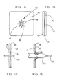
- FIG 1A is a top view of an embodiment of the present invention 10 incorporated into an implantable patch material 12.
- Figure 1B is a side view of this embodiment generally illustrating the relationship of the components.
- a framework 14 is surrounded by a layer of implantable polymeric material 18.
- the framework 14 delimits an opening 16 that is fully covered with a breachable barrier material 17.
- the polymer layer 18 is sandwiched between two layers of implantable patch material 12, 13 so as to reveal the framework 14, opening 16, and breachable barrier material 17 of the present invention.
- the implantable patch material or other wall components are considered part of the invention.
- implantable medical devices having tubular configurations are also suitable for use with the present invention.
- Tubular medical devices are generally cylindrical in shape and not confined to having parallel walls.
- tubular medical devices have geometries with at least one inlet and at least one outlet.
- the shape of the framework 14 is chosen to provide structural support to the breachable barrier material 17 while it fully covers opening 16.
- the shape and composition of the framework also allows the framework to be readily deformed and displaced to peripheral regions of the opening to form a permanent framed aperture.
- the particular shape of the framework illustrated in Figure 1A, et. al ., is preferred but not limiting.
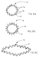
- Figures 8B and 8C illustrate frameworks having circular configurations 70 incorporating varying numbers of peaks 76 and valleys 78. It is also contemplated in the present invention that the distance between the peaks 76 and valleys 78 ( i . e ., amplitude) can be varied broadly, thereby enabling a wide range of framework geometries to be formed.
- Supporting leg struts 74 can also be incorporated into the framework design to enhance attachment to surrounding wall materials.
- Other non-circular configurations 79 of the framework 14 are also contemplated.
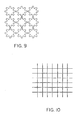
- Figures 9 and 10 illustrate that the framework can be in the form of an array of openings. These embodiments provide a choice of locations for the framed aperture as well as the number of framed apertures.
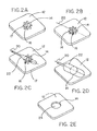
- Figures 2A-2E illustrate the construct of Figures 1A and 1B in use.
- Figure 2A is a perspective view of the construct as it might appear at an implantation site.
- Figure 2B shows a guide wire 20 from a catheter, or other device, having penetrated and breached the breachable barrier material 17.
- Figure 2C depicts an expandable balloon catheter 22 in a deflated state being introduced through the breached barrier material into opening 16 with guide wire 20.
- Figure 2D illustrates inflation of the expandable balloon catheter 22 and deformation of framework 14. As the framework 14 is deformed, opening 16 is enlarged and expanded in area.
- Figure 2E shows the resulting permanent aperture 24 framed with altered framework 14 in implantable patch material 12.
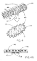
- Figure 3A illustrates the present invention 15 as a component of a tubular vascular graft 30.
- framework 14 delimiting opening 16 is fully covered by breachable barrier material 17 and incorporated into wall portion 32 of vascular graft 30.
- breachable barrier material 17 When the invention is operated, fluid communication across wall portion 32 to luminal space 34 is established.
- Figure 3B illustrates an embodiment of the present invention 19 having an implantable patch material 11 component.
- the implantable patch material is attached to an implantable vascular prosthesis 30 by sewing.
- Other suitable means of attaching the present invention to a wall of an implantable medical device include, but are not limited to, adhering, ultrasonic or radio frequency welding, lamination, stapling, and covering the medical device with a membrane or film to include the present invention.
- FIG. 4 illustrates an embodiment of the present invention 44 incorporated into an implantable tubular endovascular device 40.
- the endovascular device 40 is a bifurcated design commonly used to treat aortic aneurysms and includes a main body, or trunk, portion 50 and two leg portions 52, 54.
- the endovascular device has a stent frame 42 and wall means 48.
- Several fully covered framework elements of the present invention are incorporated into the wall means 48 of the stent-graft 40.
- This embodiment of the present invention provides multiple sites for forming side branches in stent-grafts and other endovascular devices as means for providing selective perfusion and/or drainage of the implantation site.
- the framework component of the present invention is preferably incorporated into the device separately from the support elements.
- the framework of the present invention underlies and is discrete from the support elements of the implantable medical device.
- the location of the present invention is not limited to contact or close proximity to support elements or wall components of an implantable medical device. Indeed, the present invention can be positioned in any desired location in an implantable medical device.
- FIG. 5 A clinical application of the embodiment illustrated in Figure 4 is depicted in Figures 5 and 6.
- AAA abdominal aortic aneurysm
- AA proximal aorta
- IAs distal iliac arteries
- the barrier properties of the stent-graft wall 48 occlude blood flow to the branching RA on both sides.
- one or more units 44 of the present invention are selected and utilized.
- FIGS 7A-7D The interventional procedure required to access and operate the present invention is illustrated in Figures 7A-7D.
- a guide catheter 36 is positioned under fluoroscopic guidance to direct a guide-wire 20 toward the center of one of the plurality of available inventions 44 that is in appropriate alignment with the RA.
- the framework 14 is altered in shape to the desired aperture size using a balloon catheter 22. Further inflation of the balloon 22 achieves the desired deformation of the framework 14 and formation of a permanent framed aperture 64 having a size appropriate for the RA. Once formed, the permanent framed aperture 64 provides for RA blood perfusion 62 in accordance with normal AA blood flow 60.
- the present invention can be constructed of a variety of implantable materials.
- the breachable barrier material has a composition, structure, and/or thickness sufficient to at least partially bar liquids, including blood and other physiological fluids, from crossing the material, yet have sufficient structural weakness to be readily breached, perforated, or otherwise structurally disrupted with surgical instruments, or the like.
- the breachable barrier material can be made of non-biodegradable polymers, bio-degradable polymers, and elastomers, either alone or in combination. Elastomers in the breachable barrier materials can augment uncovering of the fully covered opening following breach of the barrier material.
- the breachable barrier material can be provided with filler materials that also augment breaching of the barrier material or assist in locating the invention at an implantation site.
- Suitable surgical instruments or tools for use in breaching the barrier material at an implantation site include, but are not limited to, guide-wires, Colapinto® needles, Rotablators®, and other ablation instruments utilizing radio-frequency energy, ultrasonic sound, microwave energy, or laser light.
- Suitable non-biodegradable polymers include, but are not limited to, polyester, polytetrafluoroethylene, polyamide, and polyurethane.
- the preferred material for the breachable barrier material is a porous expanded, or stretched, polytetrafluoroethylene material.
- Suitable bio-degradable polymers include, but are not limited to, materials made of polymers or copolymers possessing one or more of the following monomeric components: glycolide (glycolic acid); lactide (d-lactide, l-lactide, d,l-lactide); trimethylene carbonate; p-dioxanone; caprolactone, and hydroxybutyrate, hydroxyvalerate.
- Elastomeric materials suitable for use in the present invention include, but are not limited to, fluoroelastomers, polyurethane.
- Suitable filler materials for incorporation into the breachable barrier material include, but are not limited to, graphite, titanium oxide (TiO), barium, vitamin E, gadolinium, lossy materials, and other radio-opaque compositions.
- the breachable barrier material can be applied to the framework as a single layer or in multiple layers. When using multiple layers of breachable barrier material, it is preferred to orient the individual layers in different directions (see e.g. Figure 11).
- the framework is made of materials that are capable of supporting the breachable barrier material while the barrier material is fully covering the opening delimited by the framework.
- the materials of the framework permit the framework to be readily shaped, reshaped, or otherwise altered in configuration while the invention is located at an implantation site.
- the framework can be made of malleable materials, plastically deformable materials, and/or self-expanding ( i . e ., super-elastic) metals or polymers. When materials are used that do not lend themselves to visualization with fluoroscopy, x-ray imagining, magnetic resonance imaging, etc., radio-opaque or other imaging compounds can be introduced into the framework materials.
- the materials of the framework also need to be sufficiently resilient to provide permanent reinforcement of peripheral regions of the aperture under physiological conditions.
- the framework component can serve as anchoring means for other medical devices 90 attached thereto (e.g., Figure 7E).
- Suitable materials for the framework include, but are not limited to, implantable metals such as gold, silver, tantalum, tungsten, and chromium, implantable metal alloys such as stainless steel, nitinol metal, and implantable polymers such as polyurethanes, fluorinated ethylene propylene, and polytetrafluoroethylene.
- the framework can be made by molding, casting, laser cutting and/or laser machining, stamping, photo-etching, wire-forming, electrical discharge machining (EDM), bent wire techniques, or other suitable fabrication method.
- any implantable material can be used for the component.
- Suitable materials include but are not limited to, implantable metals, implantable metal alloys, implantable polymers such as polyester (Dacron®), polyamide (Nylon), polytetrafluoroethylene, silicone, and polyurethane.
- the present invention can be constructed in a variety of ways.
- the invention can be made by attaching the breachable barrier material to the framework material with adhesives, heat, pressure, and/or ultrasonic welding.
- the breachable barrier material can be attached to an implantable medical device with similar methodologies.
- the invention can also be incorporated into an implantable medical device by molding, sewing, wrapping with a film or membrane, and/or mechanical fixation.
- An implantable medical device made of an expanded polytetrafluoroethylene (ePTFE) in the form of a tube or sheet can be supplied with an embodiment of the present invention by first cutting a hole in the ePTFE slightly smaller than the largest diameter of the framework component. Next, a powder coating of fluorinated ethylene propylene (FEP) is applied to both sides of the framework material and the framework material placed over the hole in the ePTFE material. A suitably sized piece of breachable barrier material is placed over the framework component. Heat and pressure are applied to the combination to attach the materials together.
- FEP fluorinated ethylene propylene
- Another method of attaching the present invention to an implantable medical device involves applying an adhesive material, such a room temperature vulcanizing (RTV) silicone, to both sides of the framework material and pressing one side of the framework onto a wall of the medical device having a suitably sized hole formed therein. A suitable breachable barrier material is then pressed onto the other adhesive-coated side of the framework component. Any excess barrier material is trimmed away from the framework to complete the installation.
- an adhesive material such as a room temperature vulcanizing (RTV) silicone
- Yet another method of attaching the present invention to an implantable medical device involves placing a framework component over a suitably sized hole in a wall of the medical device and wrapping one or more layers of a biocompatible film over the framework component.
- the wrapped film layer(s) can also serve as the breachable barrier material.
- the film wrapping material can be further secured by heating the construction.
- the present invention can be attached to the medical device in such a way that the opening is accessibly through holes in the meshwork.
- an adhesive-coated framework material is placed on a breachable barrier material. Additional adhesive is placed on perimeter regions of the barrier material.
- a meshwork device is placed over this combination so the opening of the present invention is accessible through one or more holes in the meshwork. Pressure is applied to the construct to adhere the components together.
- a preferred implantable medical device is a woven mesh material commercially available from Davol, Inc. under the trade name Bard® MarlexTM Mesh ⁇ Monofilament Knitted Polypropylene (Catalog No. 011265).
- a planar sheet embodiment of the present invention approximately 8.3cm (3.25") by 13.3cm (5.25"), was constructed as follows.
- a first layer of an expanded polytetrafluoroethylene (ePTFE) sheet material having a thickness of about 0.4mm was obtained from the Medical Products Division of W.L. Gore & Associates, Inc., Flagstaff, AZ under the tradename GORE-TEX® Cardiovascular Patch as part number 1800610004 ( Figure 12, part A1).
- ePTFE expanded polytetrafluoroethylene
- a second layer of a fluoro-elastomeric sheet material composed of a thermoplastic copolymer of tetrafluoroethylene (TFE) and perfluoro(methyl vinyl ether) (PMVE) was constructed by compression molding the crumb form of the copolymer at a temperature of about 250° C to form a sheet about 0.2mm (0.008") in thickness (Figure 12, part A3).
- the resulting material had the attributes described in TABLE 1 below.
- a third layer of sheet material (Figure 12, part A4) is composed of ePTFE made according to US Patent 4,482,516, issued to Gore.
- the sheet material was approximately 0.17mm thick with an average fibril length of greater than about 10 microns.
- a sheet of medical grade 316 stainless steel was obtained from Laserage Technologies, Inc., Waukegan, III. for use in constructing a framework.
- the framework was laser machined into an undulating pattern having a continuous, generally circular, ringed configuration ( Figure 12, part A2).
- the thickness of the framework was about 0.4mm (0.016").
- the minimum distance between individual framework elements located opposite one another in the opening delimited by the framework was about 0.2mm (0.008").
- Components 100, 102, 103, and 104 were placed between layers of high temperature padding material and aluminum plates ( Figure 12, parts 105, 106).
- the aluminum plates were approximately 15.2cm (6") square and 0.062" thick.
- the high temperature padding material 105 was made of GORE-TEX® Soft Tissue Patch having a thickness of about 2mm (0.079") available from the Medical Products Division of W.L. Gore & Associates, Inc., Flagstaff, AZ as part number 1310015020.
- the assembly was placed in a heated Carver press and laminated together in the arrangement shown in Figure 12 for about 5 minutes, at about 200° C with a pressure of about 0.5Mpa (80 lb/in 2 ). Following the compression cycle in the press, the padding material was discarded.
- a 4mm hole was then cut though all three layers of material at the center point of the reinforcement element using a 4mm sharpened coring punch.
- a layer of discontinuous fluorinated ethylene propylene (FEP) coating was placed between each layer of ePTFE material. These combined materials were placed over the cutout hole and secured in place using a heated soldering iron applied around the outer perimeter of the cutout hole. Excess film material was than trimmed from the final assembly and the edges tacked down thoroughly with the heated soldering iron. The resulting article is shown in Figure 13.
- Characteristic Target PMVE wt% about 60% TFE wt% About 40% 100% Secant Modulus About 2.1-2.2 MPa Softening Temperature ⁇ 275° C Thermal Degradation Temp. >300° C Melt Flow Index . >2.0 Durometer 60-80 Shore A
- This example describes a tubular vascular graft having the article of Example 1 incorporated into the wall of the tubular graft.
- the article of Example 1 was trimmed and sewn into a corresponding hole cut through the wall of an ePTFE vascular graft.
- the ePTFE vascular graft was a GORE-TEX® Vascular Graft available from the Medical Products Division of W.L. Gore & Associates, Inc., Flagstaff, AZ as part number SA1604.
- the article from Example 1 was sewn into the corresponding hole of the tubular construct with an ePTFE suture material obtained from Medical Products Division of W.L. Gore & Associates, Inc. Flagstaff, AZ under the tradename GORE-TEX® Suture as part number CV-5.
- the resulting article is shown in Figure 3B.
Landscapes
- Health & Medical Sciences (AREA)
- General Health & Medical Sciences (AREA)
- Animal Behavior & Ethology (AREA)
- Public Health (AREA)
- Veterinary Medicine (AREA)
- Oral & Maxillofacial Surgery (AREA)
- Transplantation (AREA)
- Vascular Medicine (AREA)
- Life Sciences & Earth Sciences (AREA)
- Biomedical Technology (AREA)
- Pulmonology (AREA)
- Cardiology (AREA)
- Engineering & Computer Science (AREA)
- Gastroenterology & Hepatology (AREA)
- Heart & Thoracic Surgery (AREA)
- Epidemiology (AREA)
- Chemical & Material Sciences (AREA)
- Medicinal Chemistry (AREA)
- Dermatology (AREA)
- Prostheses (AREA)
- Materials For Medical Uses (AREA)
- Surgical Instruments (AREA)
Claims (33)
- Implantierbare medizinische Einrichtung, umfassend einen Rahmen, welcher eine Öffnung mit einer ersten Fläche begrenzt, und ein brechbares Barrierematerial, welches die Öffnung vollständig bedeckt, wobei eine permanente Apertur mit einer zweiten Fläche gebildet wird, welche einem Bruch des brechbaren Materials folgt, und der Rahmen anpassbar ist, um in einer Form geändert zu werden.
- Implantierbare medizinische Einrichtung nach Anspruch 1, wobei der Rahmen in ein medizinisches Gerät eingebracht ist.
- Implantierbare medizinische Einrichtung nach Anspruch 2, wobei die medizinische Einrichtung eine vaskuläre Prothese ist.
- Implantierbare medizinische Einrichtung nach Anspruch 3, wobei die vaskuläre Prothese ein vaskuläres Transplantat ist.
- Implantierbare medizinische Einrichtung nach Anspruch 4, wobei die vaskuläre Prothese ein Stent-Transplantat ist.
- Implantierbare medizinische Einrichtung nach Anspruch 5, wobei die Einrichtung von Stützelementen des Stent-Transplantats verschieden ist.
- Implantierbare medizinische Einrichtung nach Anspruch 4, wobei die vaskuläre Prothese ein chirurgischer Patch ist.
- Implantierbare medizinische Einrichtung nach Anspruch 1, wobei das brechbare Barrierematerial ein Fluorpolymer umfasst.
- Implantierbare medizinische Einrichtung nach Anspruch 8, wobei das Fluorpolymer ein Polytetrafluorethylen-Material ist.
- Implantierbare medizinische Einrichtung nach Anspruch 1, wobei das brechbare Barrierematerial ein biologisch abbaubares Material umfasst.
- Implantierbare medizinische Einrichtung nach Anspruch 1, wobei das brechbare Barrierematerial ein Füllmaterial umfasst.
- Implantierbare medizinische Einrichtung nach Anspruch 1, wobei das brechbare Barrierematerial einen Elastomer umfasst.
- Implantierbare medizinische Einrichtung nach Anspruch 1, wobei der Rahmen aus einem implantierbaren Metall gefertigt ist.
- Implantierbare medizinische Einrichtung nach Anspruch 1, wobei der Rahmen aus einem implantierbaren Polymer gefertig ist.
- Implantierbare medizinische Einrichtung umfassend eine durchgängige Wand, wenigstens einen Rahmen in der Wand, welcher eine Öffnung mit einer ersten Fläche begrenzt, ein brechbares Barrierematerial, welches die Öffnung vollständig bedeckt, wobei eine permanente Apertur mit einer zweiten Fläche gebildet wird, welche einem Bruch des brechbaren Materials folgt, und der Rahmen anpassbar ist, um in einer Form geändert zu werden und einen verstärkten peripheren Bereich in der durchgängigen Wand zu haben.
- Implantierbare medizinische Einrichtung nach Anspruch 15, wobei die durchgängige Wand eine planare Geometrie hat.
- Implantierbare medizinische Einrichtung nach Anspruch 15, wobei die durchgängige Wand eine röhrenförmige Geometrie hat.
- Implantierbare medizinische Einrichtung nach Anspruch 15, wobei die durchgängige Wand eine vaskuläre Prothese ist.
- Implantierbare medizinische Einrichtung nach Anspruch 18, wobei die vaskuläre Prothese ein vaskuläres Implantat ist.
- Implantierbare medizinische Einrichtung nach Anspruch 18, wobei die vaskuläre Prothese ein chirurgischer Patch ist.
- Implantierbare medizinische Einrichtung nach Anspruch 18, wobei die vaskuläre Prothese ein Stent-Implantat ist.
- Implantierbare medizinische Einrichtung nach Anspruch 21, wobei die Einrichtung von Stützelementen des Stent-Implantats verschieden ist.
- Implantierbare medizinische Einrichtung nach Anspruch 15, wobei die Einrichtung eine Komponente einer vaskulären Prothese ist.
- Implantierbare medizinische Einrichtung nach Anspruch 23, wobei die vaskuläre Prothese ein Stent-Implantat ist.
- Implantierbare medizinische Einrichtung nach Anspruch 24, wobei die Einrichtung von Stützelementen des Stent-Implantats verschieden ist.
- Implantierbare medizinische Einrichtung nach Anspruch 15, wobei die durchgängige Wand ein Fluorpolymer umfasst.
- Implantierbare medizinische Einrichtung nach Anspruch 26, wobei das Fluorpolymer ein Polytetrafluorethylen-Material ist.
- Implantierbare medizinische Einrichtung nach Anspruch 15, wobei der Rahmen aus einem implantierbaren Metall gefertigt ist.
- Implantierbare medizinische Einrichtung nach Anspruch 15, wobei das brechbare Barrierematerial ein Fluorpolymer umfasst.
- Implantierbare medizinische Einrichtung nach Anspruch 29, wobei das Fluorpolymer ein Polytetrafluorethylen-Material ist.
- Implantierbare medizinische Einrichtung nach Anspruch 15, wobei das brechbare Barrierematerial ein biologisch abbaubares Material umfasst.
- Implantierbare medizinische Einrichtung nach Anspruch 15, wobei das brechbare Barrierematerial ein Füllmaterial umfasst.
- Implantierbare medizinische Einrichtung nach Anspruch 15, wobei das brechbare Barrierematerial ein Elastomer umfasst.
Applications Claiming Priority (3)
| Application Number | Priority Date | Filing Date | Title |
|---|---|---|---|
| US251031 | 2002-09-20 | ||
| US10/251,031 US20040059406A1 (en) | 2002-09-20 | 2002-09-20 | Medical device amenable to fenestration |
| PCT/US2003/029200 WO2004026181A1 (en) | 2002-09-20 | 2003-09-16 | Medical device amenable to fenestration |
Publications (2)
| Publication Number | Publication Date |
|---|---|
| EP1539037A1 EP1539037A1 (de) | 2005-06-15 |
| EP1539037B1 true EP1539037B1 (de) | 2005-12-07 |
Family
ID=31992633
Family Applications (1)
| Application Number | Title | Priority Date | Filing Date |
|---|---|---|---|
| EP03754655A Expired - Lifetime EP1539037B1 (de) | 2002-09-20 | 2003-09-16 | Medizinisches gerät mit fenster |
Country Status (8)
| Country | Link |
|---|---|
| US (2) | US20040059406A1 (de) |
| EP (1) | EP1539037B1 (de) |
| JP (1) | JP4571498B2 (de) |
| AT (1) | ATE311834T1 (de) |
| AU (1) | AU2003272473B2 (de) |
| CA (1) | CA2498176C (de) |
| DE (1) | DE60302674T2 (de) |
| WO (1) | WO2004026181A1 (de) |
Cited By (1)
| Publication number | Priority date | Publication date | Assignee | Title |
|---|---|---|---|---|
| DE102006024245A1 (de) * | 2006-05-23 | 2007-08-02 | Siemens Ag | Medizinisches Instrument und Verfahren zur Lokalisierung desselben im menschlichen Körper |
Families Citing this family (118)
| Publication number | Priority date | Publication date | Assignee | Title |
|---|---|---|---|---|
| US6599316B2 (en) | 1996-11-04 | 2003-07-29 | Advanced Stent Technologies, Inc. | Extendible stent apparatus |
| US6325826B1 (en) | 1998-01-14 | 2001-12-04 | Advanced Stent Technologies, Inc. | Extendible stent apparatus |
| AU4896797A (en) * | 1996-11-04 | 1998-05-29 | Davidson, Charles | Extendible stent apparatus and method for deploying the same |
| US7341598B2 (en) | 1999-01-13 | 2008-03-11 | Boston Scientific Scimed, Inc. | Stent with protruding branch portion for bifurcated vessels |
| US7220275B2 (en) | 1996-11-04 | 2007-05-22 | Advanced Stent Technologies, Inc. | Stent with protruding branch portion for bifurcated vessels |
| US6835203B1 (en) | 1996-11-04 | 2004-12-28 | Advanced Stent Technologies, Inc. | Extendible stent apparatus |
| US8257425B2 (en) * | 1999-01-13 | 2012-09-04 | Boston Scientific Scimed, Inc. | Stent with protruding branch portion for bifurcated vessels |
| DE60021173T2 (de) * | 1999-01-27 | 2006-04-27 | Boston Scientific Ltd., St Michael | Bifurkationsstenteinführsystem |
| CN1409622A (zh) * | 1999-09-23 | 2003-04-09 | 先进扩张技术公司 | 分叉支架系统和方法 |
| AU2002250189A1 (en) | 2001-02-26 | 2002-09-12 | Scimed Life Systems, Inc. | Bifurcated stent and delivery system |
| KR100893070B1 (ko) * | 2002-09-19 | 2009-04-17 | 엘지전자 주식회사 | 무선통신 시스템의 멀티캐스트 서비스 제공 및 수신 방법, 그리고 그 장치 |
| US7637942B2 (en) * | 2002-11-05 | 2009-12-29 | Merit Medical Systems, Inc. | Coated stent with geometry determinated functionality and method of making the same |
| US7875068B2 (en) * | 2002-11-05 | 2011-01-25 | Merit Medical Systems, Inc. | Removable biliary stent |
| US7959671B2 (en) * | 2002-11-05 | 2011-06-14 | Merit Medical Systems, Inc. | Differential covering and coating methods |
| US9125733B2 (en) * | 2003-01-14 | 2015-09-08 | The Cleveland Clinic Foundation | Branched vessel endoluminal device |
| EP3141215B1 (de) * | 2003-01-14 | 2021-03-24 | The Cleveland Clinic Foundation | Endoluminale vorrichtung für verzweigte gefässe |
| US7407509B2 (en) | 2003-01-14 | 2008-08-05 | The Cleveland Clinic Foundation | Branched vessel endoluminal device with fenestration |
| US8298280B2 (en) | 2003-08-21 | 2012-10-30 | Boston Scientific Scimed, Inc. | Stent with protruding branch portion for bifurcated vessels |
| ATE402666T1 (de) * | 2003-10-10 | 2008-08-15 | Cook Inc | Dehnbares prothesenfenster |
| ATE440564T1 (de) * | 2003-10-10 | 2009-09-15 | Cleveland Clinic Foundation | Endoluminale prothese mit verbindbaren modulen |
| EP3424463A1 (de) * | 2003-11-08 | 2019-01-09 | Cook Medical Technologies LLC | Aorta- und gefässverzweigungsstentgrafts und system |
| US8007528B2 (en) * | 2004-03-17 | 2011-08-30 | Boston Scientific Scimed, Inc. | Bifurcated stent |
| US8048140B2 (en) | 2004-03-31 | 2011-11-01 | Cook Medical Technologies Llc | Fenestrated intraluminal stent system |
| WO2005099629A1 (en) | 2004-03-31 | 2005-10-27 | Cook Incorporated | Stent deployment device |
| JP5054524B2 (ja) | 2004-06-08 | 2012-10-24 | アドバンスド ステント テクノロジーズ, インコーポレイテッド | 分岐管用突出枝部を備えたステント |
| US8043354B2 (en) | 2004-06-16 | 2011-10-25 | William A. Cook Australia Pty. Ltd. | Thoracic deployment device and stent graft |
| US8062214B2 (en) | 2004-08-27 | 2011-11-22 | Smith & Nephew, Inc. | Tissue resecting system |
| US9427340B2 (en) * | 2004-12-14 | 2016-08-30 | Boston Scientific Scimed, Inc. | Stent with protruding branch portion for bifurcated vessels |
| CA2608357A1 (en) * | 2005-05-13 | 2006-11-23 | Alveolus, Inc. | Drainage stent and associated method |
| US8317855B2 (en) * | 2005-05-26 | 2012-11-27 | Boston Scientific Scimed, Inc. | Crimpable and expandable side branch cell |
| US8480728B2 (en) * | 2005-05-26 | 2013-07-09 | Boston Scientific Scimed, Inc. | Stent side branch deployment initiation geometry |
| US20060271161A1 (en) * | 2005-05-26 | 2006-11-30 | Boston Scientific Scimed, Inc. | Selective treatment of stent side branch petals |
| DE102005029049A1 (de) * | 2005-06-21 | 2006-12-28 | Charité - Universitätsmedizin Berlin | Stent zur Implantation in einem menschlichen oder einem tierischen Gefäßvolumen |
| US7731741B2 (en) | 2005-09-08 | 2010-06-08 | Boston Scientific Scimed, Inc. | Inflatable bifurcation stent |
| US8038706B2 (en) * | 2005-09-08 | 2011-10-18 | Boston Scientific Scimed, Inc. | Crown stent assembly |
| US8043366B2 (en) * | 2005-09-08 | 2011-10-25 | Boston Scientific Scimed, Inc. | Overlapping stent |
| US20070112418A1 (en) | 2005-11-14 | 2007-05-17 | Boston Scientific Scimed, Inc. | Stent with spiral side-branch support designs |
| US20070123970A1 (en) * | 2005-11-29 | 2007-05-31 | Boston Scientific Scimed, Inc. | Bifurcation stent with overlapping crimped struts |
| US8343211B2 (en) * | 2005-12-14 | 2013-01-01 | Boston Scientific Scimed, Inc. | Connectors for bifurcated stent |
| US8435284B2 (en) * | 2005-12-14 | 2013-05-07 | Boston Scientific Scimed, Inc. | Telescoping bifurcated stent |
| US20070142904A1 (en) * | 2005-12-20 | 2007-06-21 | Boston Scientific Scimed, Inc. | Bifurcated stent with multiple locations for side branch access |
| US7540881B2 (en) | 2005-12-22 | 2009-06-02 | Boston Scientific Scimed, Inc. | Bifurcation stent pattern |
| US8900287B2 (en) * | 2006-01-13 | 2014-12-02 | Aga Medical Corporation | Intravascular deliverable stent for reinforcement of abdominal aortic aneurysm |
| US8778008B2 (en) * | 2006-01-13 | 2014-07-15 | Aga Medical Corporation | Intravascular deliverable stent for reinforcement of vascular abnormalities |
| US20070208256A1 (en) * | 2006-03-03 | 2007-09-06 | Medtronic Vascular, Inc. | Multiple Branch Tubular Prosthesis and Methods |
| US20070208411A1 (en) * | 2006-03-06 | 2007-09-06 | Boston Scientific Scimed, Inc. | Bifurcated stent with surface area gradient |
| US20070208419A1 (en) * | 2006-03-06 | 2007-09-06 | Boston Scientific Scimed, Inc. | Bifurcation stent with uniform side branch projection |
| US7833264B2 (en) * | 2006-03-06 | 2010-11-16 | Boston Scientific Scimed, Inc. | Bifurcated stent |
| US20070208415A1 (en) * | 2006-03-06 | 2007-09-06 | Kevin Grotheim | Bifurcated stent with controlled drug delivery |
| US8298278B2 (en) * | 2006-03-07 | 2012-10-30 | Boston Scientific Scimed, Inc. | Bifurcated stent with improvement securement |
| US20070233233A1 (en) * | 2006-03-31 | 2007-10-04 | Boston Scientific Scimed, Inc | Tethered expansion columns for controlled stent expansion |
| CA2649705C (en) | 2006-04-19 | 2015-12-01 | William A. Cook Australia Pty. Ltd | Twin bifurcated stent graft |
| WO2007146021A2 (en) | 2006-06-06 | 2007-12-21 | Cook Incorporated | Stent with a crush-resistant zone |
| EP2051673A2 (de) | 2006-06-23 | 2009-04-29 | Boston Scientific Limited | Bifurkationsstent mit drehscharnieren |
| US8202310B2 (en) | 2006-07-14 | 2012-06-19 | Cordis Corporation | AAA repair device with aneurysm sac access port |
| US8216267B2 (en) * | 2006-09-12 | 2012-07-10 | Boston Scientific Scimed, Inc. | Multilayer balloon for bifurcated stent delivery and methods of making and using the same |
| US7951191B2 (en) | 2006-10-10 | 2011-05-31 | Boston Scientific Scimed, Inc. | Bifurcated stent with entire circumferential petal |
| US8206429B2 (en) | 2006-11-02 | 2012-06-26 | Boston Scientific Scimed, Inc. | Adjustable bifurcation catheter incorporating electroactive polymer and methods of making and using the same |
| US8167926B2 (en) * | 2006-11-07 | 2012-05-01 | Cook Medical Technologies Llc | Fenestration for stent graft arrangements and stent graft including the same |
| US7842082B2 (en) | 2006-11-16 | 2010-11-30 | Boston Scientific Scimed, Inc. | Bifurcated stent |
| US20080177377A1 (en) * | 2006-11-16 | 2008-07-24 | Boston Scientific Scimed, Inc. | Bifurcation Stent Design with Over Expansion Capability |
| US8216298B2 (en) * | 2007-01-05 | 2012-07-10 | Medtronic Vascular, Inc. | Branch vessel graft method and delivery system |
| US7959668B2 (en) | 2007-01-16 | 2011-06-14 | Boston Scientific Scimed, Inc. | Bifurcated stent |
| US8118861B2 (en) * | 2007-03-28 | 2012-02-21 | Boston Scientific Scimed, Inc. | Bifurcation stent and balloon assemblies |
| US8647376B2 (en) * | 2007-03-30 | 2014-02-11 | Boston Scientific Scimed, Inc. | Balloon fold design for deployment of bifurcated stent petal architecture |
| US7632305B2 (en) * | 2007-07-06 | 2009-12-15 | Boston Scientific Scimed, Inc. | Biodegradable connectors |
| US7637940B2 (en) * | 2007-07-06 | 2009-12-29 | Boston Scientific Scimed, Inc. | Stent with bioabsorbable membrane |
| US20090030502A1 (en) * | 2007-07-26 | 2009-01-29 | Jichao Sun | Socket For Fenestrated Tubular Prosthesis |
| US7959669B2 (en) | 2007-09-12 | 2011-06-14 | Boston Scientific Scimed, Inc. | Bifurcated stent with open ended side branch support |
| US7833266B2 (en) | 2007-11-28 | 2010-11-16 | Boston Scientific Scimed, Inc. | Bifurcated stent with drug wells for specific ostial, carina, and side branch treatment |
| US8002816B2 (en) * | 2007-12-21 | 2011-08-23 | Cleveland Clinic Foundation | Prosthesis for implantation in aorta and method of using same |
| US8277501B2 (en) | 2007-12-21 | 2012-10-02 | Boston Scientific Scimed, Inc. | Bi-stable bifurcated stent petal geometry |
| US20090164001A1 (en) * | 2007-12-21 | 2009-06-25 | Biggs David P | Socket For Fenestrated Tubular Prosthesis |
| US8747456B2 (en) | 2007-12-31 | 2014-06-10 | Boston Scientific Scimed, Inc. | Bifurcation stent delivery system and methods |
| US20090259290A1 (en) * | 2008-04-14 | 2009-10-15 | Medtronic Vascular, Inc. | Fenestration Segment Stent-Graft and Fenestration Method |
| US20090264985A1 (en) * | 2008-04-17 | 2009-10-22 | Medtronic Vascular, Inc. | Branch Vessel Suture Stent System and Method |
| US20090287145A1 (en) * | 2008-05-15 | 2009-11-19 | Altura Interventional, Inc. | Devices and methods for treatment of abdominal aortic aneurysms |
| US8932340B2 (en) | 2008-05-29 | 2015-01-13 | Boston Scientific Scimed, Inc. | Bifurcated stent and delivery system |
| US8353943B2 (en) * | 2008-08-29 | 2013-01-15 | Cook Medical Technologies Llc | Variable weave graft with metal strand reinforcement for in situ fenestration |
| US8052741B2 (en) * | 2009-03-23 | 2011-11-08 | Medtronic Vascular, Inc. | Branch vessel prosthesis with a roll-up sealing assembly |
| DE112010002277T5 (de) * | 2009-04-23 | 2012-12-13 | Shaun L.W. Samuels | Endovaskuläre Routervorrichtung und Verfahren |
| WO2011064784A1 (en) * | 2009-11-30 | 2011-06-03 | Biflow Medical Ltd. | Method of implanting a stent graft and creating a fenestration therein |
| ES2584333T3 (es) | 2009-12-01 | 2016-09-27 | Altura Medical, Inc. | Dispositivos de endoinjerto modulares |
| DE102009060228B4 (de) * | 2009-12-23 | 2014-12-04 | Acandis Gmbh & Co. Kg | Medizinische Vorrichtungen |
| CA2748206C (en) | 2010-08-21 | 2015-06-23 | Blayne A. Roeder | Prosthesis having pivoting fenestration |
| US8702786B2 (en) | 2010-08-21 | 2014-04-22 | Cook Medical Technologies Llc | Prosthesis having pivoting fenestration |
| US8870939B2 (en) | 2010-08-21 | 2014-10-28 | Cook Medical Technologies Llc | Prosthesis having pivoting fenestration |
| US8771336B2 (en) | 2010-08-21 | 2014-07-08 | Cook Medical Technologies Llc | Endoluminal prosthesis comprising a valve replacement and at least one fenestration |
| WO2012040240A1 (en) | 2010-09-20 | 2012-03-29 | Altura Medical, Inc. | Stent graft delivery systems and associated methods |
| US20120109279A1 (en) * | 2010-11-02 | 2012-05-03 | Endologix, Inc. | Apparatus and method of placement of a graft or graft system |
| US9566149B2 (en) | 2010-11-16 | 2017-02-14 | W. L. Gore & Associates, Inc. | Devices and methods for in situ fenestration of a stent-graft at the site of a branch vessel |
| AU2011200858B1 (en) | 2011-02-28 | 2012-04-05 | Cook Medical Technologies Llc | Stent graft with valve arrangement |
| US9168162B2 (en) | 2011-11-17 | 2015-10-27 | Elgco, Llc | Methods and apparatus for treating a type 2 endoleak from within an endoluminal stent |
| US9811613B2 (en) | 2012-05-01 | 2017-11-07 | University Of Washington Through Its Center For Commercialization | Fenestration template for endovascular repair of aortic aneurysms |
| US10285833B2 (en) | 2012-08-10 | 2019-05-14 | Lombard Medical Limited | Stent delivery systems and associated methods |
| AU2012258394B1 (en) * | 2012-11-27 | 2013-03-07 | Cook Medical Technologies Llc | Stent graft having a closeable fenestration |
| US10265202B2 (en) | 2013-03-14 | 2019-04-23 | Cook Medical Technologies Llc | Prosthesis having an everting pivoting fenestration |
| WO2014144809A1 (en) | 2013-03-15 | 2014-09-18 | Altura Medical, Inc. | Endograft device delivery systems and associated methods |
| EP3078349B1 (de) * | 2015-04-10 | 2019-06-19 | Cook Medical Technologies LLC | Prothese mit fenster |
| WO2017218474A1 (en) * | 2016-06-13 | 2017-12-21 | Aortica Corporation | Systems, devices, and methods for marking and/or reinforcing fenestrations in prosthetic implants |
| JP7181856B2 (ja) | 2016-08-02 | 2022-12-01 | ボルトン メディカル インコーポレイテッド | 人工インプラントを有窓性本体に結合するためのシステム、器具、及び方法 |
| AR106485A1 (es) * | 2016-10-28 | 2018-01-17 | Barone Hector Daniel | Prótesis para la reparación de un vaso sanguíneo y método de implante |
| WO2018156847A1 (en) | 2017-02-24 | 2018-08-30 | Bolton Medical, Inc. | Delivery system and method to radially constrict a stent graft |
| WO2018156851A1 (en) | 2017-02-24 | 2018-08-30 | Bolton Medical, Inc. | Vascular prosthesis with moveable fenestration |
| WO2018156849A1 (en) | 2017-02-24 | 2018-08-30 | Bolton Medical, Inc. | Vascular prosthesis with fenestration ring and methods of use |
| ES2863978T3 (es) | 2017-02-24 | 2021-10-13 | Bolton Medical Inc | Sistema para constreñir radialmente un injerto de stent |
| WO2018156850A1 (en) | 2017-02-24 | 2018-08-30 | Bolton Medical, Inc. | Stent graft with fenestration lock |
| WO2018156848A1 (en) | 2017-02-24 | 2018-08-30 | Bolton Medical, Inc. | Vascular prosthesis with crimped adapter and methods of use |
| WO2018156852A1 (en) | 2017-02-24 | 2018-08-30 | Bolton Medical, Inc. | Stent graft delivery system with constricted sheath and method of use |
| JP7065091B2 (ja) | 2017-02-24 | 2022-05-11 | ボルトン メディカル インコーポレイテッド | 半径方向に調整可能なステントグラフト送達システム |
| CN111148484B (zh) | 2017-09-25 | 2022-12-30 | 波尔顿医疗公司 | 用于将假体植入物联接到开窗体的系统、装置和方法 |
| EP4578424A3 (de) | 2017-10-31 | 2025-07-09 | Bolton Medical, Inc. | Distale drehmomentkomponente, bereitstellungssystem |
| CN110236748B (zh) * | 2019-05-30 | 2021-03-26 | 中国人民解放军陆军军医大学第一附属医院 | 一种免订制精准体外开窗主动脉支架 |
| CN112438823A (zh) * | 2019-08-30 | 2021-03-05 | 陈兵 | 预设开窗覆膜支架及预设开窗覆膜支架系统 |
| USD998779S1 (en) * | 2020-06-05 | 2023-09-12 | W. L. Gore & Associates, Inc. | Vent |
| USD1004071S1 (en) * | 2020-11-30 | 2023-11-07 | W. L. Gore & Associates, Inc. | Vent |
| FR3126300B1 (fr) * | 2021-08-31 | 2025-04-11 | Hospices Civils Lyon | Prothèse pour endopontage en attente d’une future anastomose |
| WO2023091098A1 (en) * | 2021-11-22 | 2023-05-25 | Mehmet Hakan Akpinar | An implantable patch for vascular injuries with a blood perfusion system |
Family Cites Families (42)
| Publication number | Priority date | Publication date | Assignee | Title |
|---|---|---|---|---|
| US4482516A (en) * | 1982-09-10 | 1984-11-13 | W. L. Gore & Associates, Inc. | Process for producing a high strength porous polytetrafluoroethylene product having a coarse microstructure |
| US4988356A (en) * | 1987-02-27 | 1991-01-29 | C. R. Bard, Inc. | Catheter and guidewire exchange system |
| US5171222A (en) * | 1988-03-10 | 1992-12-15 | Scimed Life Systems, Inc. | Interlocking peel-away dilation catheter |
| US5102403A (en) * | 1990-06-18 | 1992-04-07 | Eckhard Alt | Therapeutic medical instrument for insertion into body |
| US5395335A (en) * | 1991-05-24 | 1995-03-07 | Jang; G. David | Universal mode vascular catheter system |
| US5205822A (en) * | 1991-06-10 | 1993-04-27 | Cordis Corporation | Replaceable dilatation catheter |
| US5135535A (en) * | 1991-06-11 | 1992-08-04 | Advanced Cardiovascular Systems, Inc. | Catheter system with catheter and guidewire exchange |
| US5389087A (en) * | 1991-09-19 | 1995-02-14 | Baxter International Inc. | Fully exchangeable over-the-wire catheter with rip seam and gated side port |
| US5324269A (en) * | 1991-09-19 | 1994-06-28 | Baxter International Inc. | Fully exchangeable dual lumen over-the-wire dilatation catheter with rip seam |
| US5195978A (en) * | 1991-12-11 | 1993-03-23 | Baxter International Inc. | Rapid exchange over-the-wire catheter with breakaway feature |
| US5683448A (en) * | 1992-02-21 | 1997-11-04 | Boston Scientific Technology, Inc. | Intraluminal stent and graft |
| US5334147A (en) * | 1993-04-28 | 1994-08-02 | Cordis Corporation | Rapid exchange type dilatation catheter |
| US5472425A (en) * | 1993-07-15 | 1995-12-05 | Teirstein; Paul S. | Rapid exchange catheter |
| US5336184A (en) * | 1993-07-15 | 1994-08-09 | Teirstein Paul S | Rapid exchange catheter |
| CA2169549C (en) * | 1993-08-18 | 2000-07-11 | James D. Lewis | A tubular intraluminal graft |
| US5549663A (en) * | 1994-03-09 | 1996-08-27 | Cordis Corporation | Endoprosthesis having graft member and exposed welded end junctions, method and procedure |
| US5489271A (en) * | 1994-03-29 | 1996-02-06 | Boston Scientific Corporation | Convertible catheter |
| US6579314B1 (en) * | 1995-03-10 | 2003-06-17 | C.R. Bard, Inc. | Covered stent with encapsulated ends |
| US5476589A (en) * | 1995-03-10 | 1995-12-19 | W. L. Gore & Associates, Inc. | Porpous PTFE film and a manufacturing method therefor |
| ATE314022T1 (de) * | 1995-06-01 | 2006-01-15 | Meadox Medicals Inc | Implantierbare intraluminale prothese |
| WO1997027959A1 (en) * | 1996-01-30 | 1997-08-07 | Medtronic, Inc. | Articles for and methods of making stents |
| US6432127B1 (en) * | 1996-10-11 | 2002-08-13 | Transvascular, Inc. | Devices for forming and/or maintaining connections between adjacent anatomical conduits |
| US6835203B1 (en) * | 1996-11-04 | 2004-12-28 | Advanced Stent Technologies, Inc. | Extendible stent apparatus |
| US5807355A (en) * | 1996-12-09 | 1998-09-15 | Advanced Cardiovascular Systems, Inc. | Catheter with rapid exchange and OTW operative modes |
| KR19990010304A (ko) * | 1997-07-16 | 1999-02-18 | 장양수 | 혈관용 스텐트 |
| US5984955A (en) * | 1997-09-11 | 1999-11-16 | Wisselink; Willem | System and method for endoluminal grafting of bifurcated or branched vessels |
| EP1625833A3 (de) * | 1997-11-25 | 2010-09-22 | TriVascular2, Inc. | Mehrlagige endovaskuläre Gewebeprothese |
| AUPP083597A0 (en) * | 1997-12-10 | 1998-01-08 | William A Cook Australia Pty Ltd | Endoluminal aortic stents |
| US6395018B1 (en) * | 1998-02-09 | 2002-05-28 | Wilfrido R. Castaneda | Endovascular graft and process for bridging a defect in a main vessel near one of more branch vessels |
| US6261273B1 (en) * | 1998-05-07 | 2001-07-17 | Carlos E. Ruiz | Access system for branched vessels amd methods of use |
| US6095990A (en) * | 1998-08-31 | 2000-08-01 | Parodi; Juan Carlos | Guiding device and method for inserting and advancing catheters and guidewires into a vessel of a patient in endovascular treatments |
| US6071307A (en) * | 1998-09-30 | 2000-06-06 | Baxter International Inc. | Endoluminal grafts having continuously curvilinear wireforms |
| US6398803B1 (en) * | 1999-02-02 | 2002-06-04 | Impra, Inc., A Subsidiary Of C.R. Bard, Inc. | Partial encapsulation of stents |
| US6273911B1 (en) * | 1999-04-22 | 2001-08-14 | Advanced Cardiovascular Systems, Inc. | Variable strength stent |
| BR9901540C1 (pt) * | 1999-05-17 | 2001-12-18 | Fundacao Zerbini | Dispositivo para desobstrução de lesõesateroscleróticas que englobam a origem de ramoslaterais ou localizadas em bifurcações dacirculação coronária, e respectivo processointervencionista para colocação do referidodispositivo |
| US6673103B1 (en) * | 1999-05-20 | 2004-01-06 | Scimed Life Systems, Inc. | Mesh and stent for increased flexibility |
| US6361555B1 (en) * | 1999-12-15 | 2002-03-26 | Advanced Cardiovascular Systems, Inc. | Stent and stent delivery assembly and method of use |
| US6299595B1 (en) * | 1999-12-17 | 2001-10-09 | Advanced Cardiovascular Systems, Inc. | Catheters having rapid-exchange and over-the-wire operating modes |
| US6245100B1 (en) * | 2000-02-01 | 2001-06-12 | Cordis Corporation | Method for making a self-expanding stent-graft |
| EP1404262A2 (de) * | 2001-06-18 | 2004-04-07 | Eva Corporation | Prothesenanordnung und anwendungsverfahren |
| US20030130720A1 (en) * | 2002-01-08 | 2003-07-10 | Depalma Donald F. | Modular aneurysm repair system |
| US20040054403A1 (en) * | 2002-09-18 | 2004-03-18 | Israel Henry M | Angular orientation of a stent |
-
2002
- 2002-09-20 US US10/251,031 patent/US20040059406A1/en not_active Abandoned
-
2003
- 2003-09-16 CA CA002498176A patent/CA2498176C/en not_active Expired - Lifetime
- 2003-09-16 EP EP03754655A patent/EP1539037B1/de not_active Expired - Lifetime
- 2003-09-16 AT AT03754655T patent/ATE311834T1/de not_active IP Right Cessation
- 2003-09-16 AU AU2003272473A patent/AU2003272473B2/en not_active Expired
- 2003-09-16 DE DE60302674T patent/DE60302674T2/de not_active Expired - Lifetime
- 2003-09-16 WO PCT/US2003/029200 patent/WO2004026181A1/en not_active Ceased
- 2003-09-16 JP JP2004537900A patent/JP4571498B2/ja not_active Expired - Lifetime
-
2013
- 2013-07-31 US US13/955,899 patent/US9694108B2/en not_active Expired - Fee Related
Cited By (1)
| Publication number | Priority date | Publication date | Assignee | Title |
|---|---|---|---|---|
| DE102006024245A1 (de) * | 2006-05-23 | 2007-08-02 | Siemens Ag | Medizinisches Instrument und Verfahren zur Lokalisierung desselben im menschlichen Körper |
Also Published As
| Publication number | Publication date |
|---|---|
| CA2498176C (en) | 2009-05-12 |
| CA2498176A1 (en) | 2004-04-01 |
| US9694108B2 (en) | 2017-07-04 |
| WO2004026181A1 (en) | 2004-04-01 |
| US20040059406A1 (en) | 2004-03-25 |
| AU2003272473A1 (en) | 2004-04-08 |
| EP1539037A1 (de) | 2005-06-15 |
| JP2006500107A (ja) | 2006-01-05 |
| JP4571498B2 (ja) | 2010-10-27 |
| DE60302674D1 (de) | 2006-01-12 |
| ATE311834T1 (de) | 2005-12-15 |
| DE60302674T2 (de) | 2006-08-31 |
| AU2003272473B2 (en) | 2006-12-07 |
| US20130317601A1 (en) | 2013-11-28 |
Similar Documents
| Publication | Publication Date | Title |
|---|---|---|
| EP1539037B1 (de) | Medizinisches gerät mit fenster | |
| US10682222B2 (en) | Modular vascular graft for low profile percutaneous delivery | |
| US20200330214A1 (en) | Apparatus and methods for endoluminal graft placement | |
| EP1734899B1 (de) | Eingekapselter stent graft mit verbindung zwischen den grafthüllen | |
| US11065097B2 (en) | Advanced kink-resistant stent graft | |
| EP1035810B1 (de) | Endovaskulares gewebesystem | |
| US20140005764A1 (en) | Sealing mechanism for expandable vascular device | |
| KR20160140688A (ko) | 흉복부 분기 동맥류 치료용 스텐트 조립체 | |
| JP2007536951A (ja) | 新生内膜阻害性ポリマースリーブを持つ管腔内人工血管 | |
| KR20010041603A (ko) | 혈관 내강 삽입체 | |
| JP5318604B2 (ja) | ステント構造体をaaaグラフト材料に取り付ける方法および装置 | |
| JP2020533080A (ja) | 管腔内人工血管システム | |
| KR20020012574A (ko) | 증가된 유연성을 갖는 스텐트-이식편 | |
| US20220257363A1 (en) | Bifurcated stent grafts, stents, and methods |
Legal Events
| Date | Code | Title | Description |
|---|---|---|---|
| PUAI | Public reference made under article 153(3) epc to a published international application that has entered the european phase |
Free format text: ORIGINAL CODE: 0009012 |
|
| 17P | Request for examination filed |
Effective date: 20050411 |
|
| AK | Designated contracting states |
Kind code of ref document: A1 Designated state(s): AT BE BG CH CY CZ DE DK EE ES FI FR GB GR HU IE IT LI LU MC NL PT RO SE SI SK TR |
|
| AX | Request for extension of the european patent |
Extension state: AL LT LV MK |
|
| GRAP | Despatch of communication of intention to grant a patent |
Free format text: ORIGINAL CODE: EPIDOSNIGR1 |
|
| GRAS | Grant fee paid |
Free format text: ORIGINAL CODE: EPIDOSNIGR3 |
|
| GRAA | (expected) grant |
Free format text: ORIGINAL CODE: 0009210 |
|
| AK | Designated contracting states |
Kind code of ref document: B1 Designated state(s): AT BE BG CH CY CZ DE DK EE ES FI FR GB GR HU IE IT LI LU MC NL PT RO SE SI SK TR |
|
| PG25 | Lapsed in a contracting state [announced via postgrant information from national office to epo] |
Ref country code: SK Free format text: LAPSE BECAUSE OF FAILURE TO SUBMIT A TRANSLATION OF THE DESCRIPTION OR TO PAY THE FEE WITHIN THE PRESCRIBED TIME-LIMIT Effective date: 20051207 Ref country code: BE Free format text: LAPSE BECAUSE OF FAILURE TO SUBMIT A TRANSLATION OF THE DESCRIPTION OR TO PAY THE FEE WITHIN THE PRESCRIBED TIME-LIMIT Effective date: 20051207 Ref country code: AT Free format text: LAPSE BECAUSE OF FAILURE TO SUBMIT A TRANSLATION OF THE DESCRIPTION OR TO PAY THE FEE WITHIN THE PRESCRIBED TIME-LIMIT Effective date: 20051207 Ref country code: NL Free format text: LAPSE BECAUSE OF FAILURE TO SUBMIT A TRANSLATION OF THE DESCRIPTION OR TO PAY THE FEE WITHIN THE PRESCRIBED TIME-LIMIT Effective date: 20051207 Ref country code: CZ Free format text: LAPSE BECAUSE OF FAILURE TO SUBMIT A TRANSLATION OF THE DESCRIPTION OR TO PAY THE FEE WITHIN THE PRESCRIBED TIME-LIMIT Effective date: 20051207 Ref country code: LI Free format text: LAPSE BECAUSE OF FAILURE TO SUBMIT A TRANSLATION OF THE DESCRIPTION OR TO PAY THE FEE WITHIN THE PRESCRIBED TIME-LIMIT Effective date: 20051207 Ref country code: RO Free format text: LAPSE BECAUSE OF FAILURE TO SUBMIT A TRANSLATION OF THE DESCRIPTION OR TO PAY THE FEE WITHIN THE PRESCRIBED TIME-LIMIT Effective date: 20051207 Ref country code: SI Free format text: LAPSE BECAUSE OF FAILURE TO SUBMIT A TRANSLATION OF THE DESCRIPTION OR TO PAY THE FEE WITHIN THE PRESCRIBED TIME-LIMIT Effective date: 20051207 Ref country code: FI Free format text: LAPSE BECAUSE OF FAILURE TO SUBMIT A TRANSLATION OF THE DESCRIPTION OR TO PAY THE FEE WITHIN THE PRESCRIBED TIME-LIMIT Effective date: 20051207 Ref country code: CH Free format text: LAPSE BECAUSE OF FAILURE TO SUBMIT A TRANSLATION OF THE DESCRIPTION OR TO PAY THE FEE WITHIN THE PRESCRIBED TIME-LIMIT Effective date: 20051207 |
|
| REG | Reference to a national code |
Ref country code: GB Ref legal event code: FG4D |
|
| REG | Reference to a national code |
Ref country code: CH Ref legal event code: EP |
|
| REG | Reference to a national code |
Ref country code: IE Ref legal event code: FG4D |
|
| REF | Corresponds to: |
Ref document number: 60302674 Country of ref document: DE Date of ref document: 20060112 Kind code of ref document: P |
|
| PG25 | Lapsed in a contracting state [announced via postgrant information from national office to epo] |
Ref country code: GR Free format text: LAPSE BECAUSE OF FAILURE TO SUBMIT A TRANSLATION OF THE DESCRIPTION OR TO PAY THE FEE WITHIN THE PRESCRIBED TIME-LIMIT Effective date: 20060307 Ref country code: DK Free format text: LAPSE BECAUSE OF FAILURE TO SUBMIT A TRANSLATION OF THE DESCRIPTION OR TO PAY THE FEE WITHIN THE PRESCRIBED TIME-LIMIT Effective date: 20060307 Ref country code: SE Free format text: LAPSE BECAUSE OF FAILURE TO SUBMIT A TRANSLATION OF THE DESCRIPTION OR TO PAY THE FEE WITHIN THE PRESCRIBED TIME-LIMIT Effective date: 20060307 Ref country code: BG Free format text: LAPSE BECAUSE OF FAILURE TO SUBMIT A TRANSLATION OF THE DESCRIPTION OR TO PAY THE FEE WITHIN THE PRESCRIBED TIME-LIMIT Effective date: 20060307 |
|
| PG25 | Lapsed in a contracting state [announced via postgrant information from national office to epo] |
Ref country code: ES Free format text: LAPSE BECAUSE OF FAILURE TO SUBMIT A TRANSLATION OF THE DESCRIPTION OR TO PAY THE FEE WITHIN THE PRESCRIBED TIME-LIMIT Effective date: 20060318 |
|
| PG25 | Lapsed in a contracting state [announced via postgrant information from national office to epo] |
Ref country code: PT Free format text: LAPSE BECAUSE OF FAILURE TO SUBMIT A TRANSLATION OF THE DESCRIPTION OR TO PAY THE FEE WITHIN THE PRESCRIBED TIME-LIMIT Effective date: 20060508 |
|
| NLV1 | Nl: lapsed or annulled due to failure to fulfill the requirements of art. 29p and 29m of the patents act | ||
| PG25 | Lapsed in a contracting state [announced via postgrant information from national office to epo] |
Ref country code: HU Free format text: LAPSE BECAUSE OF FAILURE TO SUBMIT A TRANSLATION OF THE DESCRIPTION OR TO PAY THE FEE WITHIN THE PRESCRIBED TIME-LIMIT Effective date: 20060608 |
|
| REG | Reference to a national code |
Ref country code: CH Ref legal event code: PL |
|
| ET | Fr: translation filed | ||
| PG25 | Lapsed in a contracting state [announced via postgrant information from national office to epo] |
Ref country code: IE Free format text: LAPSE BECAUSE OF NON-PAYMENT OF DUE FEES Effective date: 20060918 |
|
| PG25 | Lapsed in a contracting state [announced via postgrant information from national office to epo] |
Ref country code: MC Free format text: LAPSE BECAUSE OF NON-PAYMENT OF DUE FEES Effective date: 20060930 |
|
| PLBE | No opposition filed within time limit |
Free format text: ORIGINAL CODE: 0009261 |
|
| STAA | Information on the status of an ep patent application or granted ep patent |
Free format text: STATUS: NO OPPOSITION FILED WITHIN TIME LIMIT |
|
| 26N | No opposition filed |
Effective date: 20060908 |
|
| REG | Reference to a national code |
Ref country code: IE Ref legal event code: MM4A |
|
| PG25 | Lapsed in a contracting state [announced via postgrant information from national office to epo] |
Ref country code: EE Free format text: LAPSE BECAUSE OF FAILURE TO SUBMIT A TRANSLATION OF THE DESCRIPTION OR TO PAY THE FEE WITHIN THE PRESCRIBED TIME-LIMIT Effective date: 20051207 |
|
| PG25 | Lapsed in a contracting state [announced via postgrant information from national office to epo] |
Ref country code: TR Free format text: LAPSE BECAUSE OF FAILURE TO SUBMIT A TRANSLATION OF THE DESCRIPTION OR TO PAY THE FEE WITHIN THE PRESCRIBED TIME-LIMIT Effective date: 20051207 Ref country code: LU Free format text: LAPSE BECAUSE OF NON-PAYMENT OF DUE FEES Effective date: 20060916 |
|
| PG25 | Lapsed in a contracting state [announced via postgrant information from national office to epo] |
Ref country code: CY Free format text: LAPSE BECAUSE OF FAILURE TO SUBMIT A TRANSLATION OF THE DESCRIPTION OR TO PAY THE FEE WITHIN THE PRESCRIBED TIME-LIMIT Effective date: 20051207 |
|
| REG | Reference to a national code |
Ref country code: GB Ref legal event code: 732E Free format text: REGISTERED BETWEEN 20150723 AND 20150729 |
|
| REG | Reference to a national code |
Ref country code: FR Ref legal event code: PLFP Year of fee payment: 13 |
|
| REG | Reference to a national code |
Ref country code: DE Ref legal event code: R081 Ref document number: 60302674 Country of ref document: DE Owner name: W.L. GORE ASSOCIATES, INC., NEWARK, US Free format text: FORMER OWNER: GORE ENTERPRISE HOLDINGS, INC., NEWARK, DEL., US Ref country code: DE Ref legal event code: R082 Ref document number: 60302674 Country of ref document: DE Representative=s name: KLUNKER, SCHMITT-NILSON, HIRSCH, DE Ref country code: DE Ref legal event code: R081 Ref document number: 60302674 Country of ref document: DE Owner name: W.L. GORE & ASSOCIATES, INC., NEWARK, US Free format text: FORMER OWNER: GORE ENTERPRISE HOLDINGS, INC., NEWARK, DEL., US Ref country code: DE Ref legal event code: R082 Ref document number: 60302674 Country of ref document: DE Representative=s name: KLUNKER IP PATENTANWAELTE PARTG MBB, DE |
|
| REG | Reference to a national code |
Ref country code: FR Ref legal event code: TP Owner name: W.L. GORE & ASSOCIATES, INC., US Effective date: 20160510 |
|
| REG | Reference to a national code |
Ref country code: FR Ref legal event code: PLFP Year of fee payment: 14 |
|
| REG | Reference to a national code |
Ref country code: DE Ref legal event code: R082 Ref document number: 60302674 Country of ref document: DE Representative=s name: KLUNKER IP PATENTANWAELTE PARTG MBB, DE |
|
| REG | Reference to a national code |
Ref country code: FR Ref legal event code: PLFP Year of fee payment: 15 |
|
| REG | Reference to a national code |
Ref country code: FR Ref legal event code: PLFP Year of fee payment: 16 |
|
| PGFP | Annual fee paid to national office [announced via postgrant information from national office to epo] |
Ref country code: IT Payment date: 20220825 Year of fee payment: 20 Ref country code: GB Payment date: 20220819 Year of fee payment: 20 Ref country code: DE Payment date: 20220818 Year of fee payment: 20 |
|
| PGFP | Annual fee paid to national office [announced via postgrant information from national office to epo] |
Ref country code: FR Payment date: 20220818 Year of fee payment: 20 |
|
| REG | Reference to a national code |
Ref country code: DE Ref legal event code: R071 Ref document number: 60302674 Country of ref document: DE |
|
| REG | Reference to a national code |
Ref country code: GB Ref legal event code: PE20 Expiry date: 20230915 |
|
| PG25 | Lapsed in a contracting state [announced via postgrant information from national office to epo] |
Ref country code: GB Free format text: LAPSE BECAUSE OF EXPIRATION OF PROTECTION Effective date: 20230915 |