EP1538884A2 - Liquid cooling system for use in an electronic apparatus - Google Patents
Liquid cooling system for use in an electronic apparatus Download PDFInfo
- Publication number
- EP1538884A2 EP1538884A2 EP04005163A EP04005163A EP1538884A2 EP 1538884 A2 EP1538884 A2 EP 1538884A2 EP 04005163 A EP04005163 A EP 04005163A EP 04005163 A EP04005163 A EP 04005163A EP 1538884 A2 EP1538884 A2 EP 1538884A2
- Authority
- EP
- European Patent Office
- Prior art keywords
- heat
- liquid
- lamination
- plate
- liquid cooling
- Prior art date
- Legal status (The legal status is an assumption and is not a legal conclusion. Google has not performed a legal analysis and makes no representation as to the accuracy of the status listed.)
- Granted
Links
Images


Classifications
-
- F—MECHANICAL ENGINEERING; LIGHTING; HEATING; WEAPONS; BLASTING
- F28—HEAT EXCHANGE IN GENERAL
- F28F—DETAILS OF HEAT-EXCHANGE AND HEAT-TRANSFER APPARATUS, OF GENERAL APPLICATION
- F28F3/00—Plate-like or laminated elements; Assemblies of plate-like or laminated elements
- F28F3/12—Elements constructed in the shape of a hollow panel, e.g. with channels
-
- E—FIXED CONSTRUCTIONS
- E02—HYDRAULIC ENGINEERING; FOUNDATIONS; SOIL SHIFTING
- E02D—FOUNDATIONS; EXCAVATIONS; EMBANKMENTS; UNDERGROUND OR UNDERWATER STRUCTURES
- E02D29/00—Independent underground or underwater structures; Retaining walls
- E02D29/02—Retaining or protecting walls
- E02D29/0225—Retaining or protecting walls comprising retention means in the backfill
- E02D29/0241—Retaining or protecting walls comprising retention means in the backfill the retention means being reinforced earth elements
-
- E—FIXED CONSTRUCTIONS
- E02—HYDRAULIC ENGINEERING; FOUNDATIONS; SOIL SHIFTING
- E02D—FOUNDATIONS; EXCAVATIONS; EMBANKMENTS; UNDERGROUND OR UNDERWATER STRUCTURES
- E02D29/00—Independent underground or underwater structures; Retaining walls
- E02D29/02—Retaining or protecting walls
- E02D29/025—Retaining or protecting walls made up of similar modular elements stacked without mortar
-
- E—FIXED CONSTRUCTIONS
- E02—HYDRAULIC ENGINEERING; FOUNDATIONS; SOIL SHIFTING
- E02D—FOUNDATIONS; EXCAVATIONS; EMBANKMENTS; UNDERGROUND OR UNDERWATER STRUCTURES
- E02D29/00—Independent underground or underwater structures; Retaining walls
- E02D29/02—Retaining or protecting walls
- E02D29/0258—Retaining or protecting walls characterised by constructional features
- E02D29/0266—Retaining or protecting walls characterised by constructional features made up of preformed elements
-
- G—PHYSICS
- G06—COMPUTING; CALCULATING OR COUNTING
- G06F—ELECTRIC DIGITAL DATA PROCESSING
- G06F1/00—Details not covered by groups G06F3/00 - G06F13/00 and G06F21/00
- G06F1/16—Constructional details or arrangements
- G06F1/20—Cooling means
-
- H—ELECTRICITY
- H01—ELECTRIC ELEMENTS
- H01L—SEMICONDUCTOR DEVICES NOT COVERED BY CLASS H10
- H01L23/00—Details of semiconductor or other solid state devices
- H01L23/34—Arrangements for cooling, heating, ventilating or temperature compensation ; Temperature sensing arrangements
- H01L23/46—Arrangements for cooling, heating, ventilating or temperature compensation ; Temperature sensing arrangements involving the transfer of heat by flowing fluids
- H01L23/473—Arrangements for cooling, heating, ventilating or temperature compensation ; Temperature sensing arrangements involving the transfer of heat by flowing fluids by flowing liquids
-
- E—FIXED CONSTRUCTIONS
- E02—HYDRAULIC ENGINEERING; FOUNDATIONS; SOIL SHIFTING
- E02D—FOUNDATIONS; EXCAVATIONS; EMBANKMENTS; UNDERGROUND OR UNDERWATER STRUCTURES
- E02D2600/00—Miscellaneous
- E02D2600/20—Miscellaneous comprising details of connection between elements
-
- E—FIXED CONSTRUCTIONS
- E02—HYDRAULIC ENGINEERING; FOUNDATIONS; SOIL SHIFTING
- E02D—FOUNDATIONS; EXCAVATIONS; EMBANKMENTS; UNDERGROUND OR UNDERWATER STRUCTURES
- E02D2600/00—Miscellaneous
- E02D2600/40—Miscellaneous comprising stabilising elements
-
- G—PHYSICS
- G06—COMPUTING; CALCULATING OR COUNTING
- G06F—ELECTRIC DIGITAL DATA PROCESSING
- G06F2200/00—Indexing scheme relating to G06F1/04 - G06F1/32
- G06F2200/20—Indexing scheme relating to G06F1/20
- G06F2200/201—Cooling arrangements using cooling fluid
-
- H—ELECTRICITY
- H01—ELECTRIC ELEMENTS
- H01L—SEMICONDUCTOR DEVICES NOT COVERED BY CLASS H10
- H01L2924/00—Indexing scheme for arrangements or methods for connecting or disconnecting semiconductor or solid-state bodies as covered by H01L24/00
- H01L2924/0001—Technical content checked by a classifier
- H01L2924/0002—Not covered by any one of groups H01L24/00, H01L24/00 and H01L2224/00
-
- H—ELECTRICITY
- H01—ELECTRIC ELEMENTS
- H01L—SEMICONDUCTOR DEVICES NOT COVERED BY CLASS H10
- H01L2924/00—Indexing scheme for arrangements or methods for connecting or disconnecting semiconductor or solid-state bodies as covered by H01L24/00
- H01L2924/30—Technical effects
- H01L2924/301—Electrical effects
- H01L2924/3011—Impedance
Definitions
- a purpose of that invention disclosed in the patent document 3 is to prevent a heat sink of lamination plate type from generating the defects therein, and also to obtain an improvement on reliability and cooling capacity of an apparatus or equipment, by installing that heat sink therein, as was described in the column "Problems to be Solved" in the specification thereof.
- a liquid cooling system comprising: a heat-receiving element, being thermally connected with a heat-generation part; a pump for transporting a liquid to said heat-receiving element; and a radiator for receiving heat from said heat-generation part with an aid of said pump, and for radiating heat of the liquid, wherein: said heat-receiving element is made up with a lamination plate, being formed through punching process, and said lamination plate comprises a flow passage, within which the liquid communicates and are provided a plural number of fins, and further said pump and said radiator are connected with said heat-receiving member through conduits.
- the flow passage is meandered or zigzagged around.
- the liquid cooling jacket 100 is made up with two (2) pieces of plates, and basically, it is made up with an upper lamination plate 9, which is formed through a press process, and a plate-like lower layer plate 10.
- the upper lamination plate 9 is formed the flow passage 8 in a zigzag-like manner (or "S"-like shaped) through extrusion forming obtained by the press process, and further in this extrusion forming portion are formed a plural number of concave portions 13.
- a liquid cooling system 120 is built up with a pump 500, a radiator 200, a liquid cooling jacket 100 and a fan 300 for use of cooling down the radiator, and also pipe 400, etc.
- the liquid cooling jacket which was explained in either one of the embodiments; i.e., from the embodiment 1 to embodiment 4.
- the thermal resistance in the liquid cooling jacket 100 which is made up through the conventional manufacturing method, such as, the extrusion forming, for example, comes to be larger than that in the radiator 200.
Abstract
Description
- The present invention relates to an electronic apparatus having a cooling system of a heat-generation element thereof.
- Disclosure is made on the structure of a conventional liquid cooling jacket for use in an electronic apparatus, for example, in the following
patent documents - In those
patent documents - On the other hand, with a method for processing with relatively low costs, such as extruding process, for example, but there is a limit in the height and the pitch of the fins, which can be processed; therefore, it is difficult to maintain the cooling performance or capacity thereof to be favorable.
- Also, with the structure of providing the injection nozzle, it increases the thickness of the liquid cooling jacket; therefore it is difficult to apply it, in particular, into a narrow space.
- In the following
patent document 3, there is disclosed a heat sink, being constructed by piling up lamination plates in a direction of the thickness thereof. However, thispatent document 3, since it pays the consideration onto, mainly, such as preventing the generation of defects, and/or improvement on an evenness of temperature within the flow passages, therefore there is made no mentioning about a promotion of heat transfer, through an increase of the heat transfer area within the flow passage itself and/or an improvement on the heat transfer coefficient thereof. - In the following
patent document 4, there is disclosed the structure of a heat sink, applying a lamination plate formed by the press processing. However in thepatent document 4, there is made no mentioning about the promotion of heat conductivity or transfer within the flow passage itself. - In the following
patent document 5, there is disclosed the structure of a liquid cooling heat sink, in which an inner fin is inserted therein, for obtaining the promotion of heat transfer of the flow passages itself. However, with'thepatent document 5, since a brazing material is put therebetween, which has remarkably low heat conductivity, then heat transmission in the direction perpendicular to a base surface is obstructed at this portion, and therefore it is impossible to obtain such the inner thermal resistance that can be obtained when it is formed into a one body, which is processed through the cutting process. - Patent Document 1: Japanese Patent Laying-Open No. Hei
8-279578 (1996), in
particular page 5 and Figs. 1-5; - Patent Document 2: Japanese Patent Laying-Open No. Hei 8-31994 (1996), in particular pages 6-7 and Figs. 1-4;
- Patent Document 3: Japanese Patent Laying-Open No. Hei
9-102568 (1997), in
particular page 4 and Fig. 1; - Patent Document 4: Japanese Patent Laying-Open No. 2003-7944 (2003), in particular pages 2-3 and Fig. 2; and
- Patent Document 5: Japanese Patent Laying-Open No. 2002-170915 (2002), in particular pages 2-4 and Figs. 1-5.
-
- As was mentioned above, it must be said that the structure is already known, in which a thin films made of a metal are laminated in the thick direction, so as to form a flow passage within an inside thereof, in the
patent document 3 mentioned above. - However, this
patent document 3 never mention about the promotion of heat transfer of the flow passage itself. - Thus, a purpose of that invention disclosed in the
patent document 3 is to prevent a heat sink of lamination plate type from generating the defects therein, and also to obtain an improvement on reliability and cooling capacity of an apparatus or equipment, by installing that heat sink therein, as was described in the column "Problems to be Solved" in the specification thereof. - And,
inthe patent document 3 , a pair of end plates are provide, for holding a flow passage plate and a communicating plate from both sides thereof, and further they are disposed at positions corresponding to the flow passage of high temperature and that of low temperature, thereby achieving an averaging of temperature. - In this manner, though the
patent document 3 talks about an improvement on the cooling capacity, however it is impossible to promote or enhance the heat conductivity of the heat sink by itself. - Accordingly, an object according to the present invention is to provide an electronic apparatus having a liquid cooling jacket and a liquid cooling system, for use in cooling thereof, with aiming a promotion or enhancement of heat transfer as well as thermal conductivity of a flow passage itself.
- For accomplishing the object mentioned above, according to the present invention, there is provided a liquid cooling system, comprising: a heat-receiving element, being thermally connected with a heat-generation part; a pump for transporting a liquid to said heat-receiving element; and a radiator for receiving heat from said heat-generation part with an aid of said pump, and for radiating heat of the liquid, wherein: said heat-receiving element is made up with a lamination plate, being formed through punching process, and said lamination plate comprises a flow passage, within which the liquid communicates and are provided a plural number of fins.
- Also, according to the present invention, for accomplishing the above-mentioned object, in the liquid cooling system, as mentioned above, wherein: said lamination plate has a first lamination plate having a hole at a central portion thereof, and a second lamination plate having an opened cut-out portion at one end thereof and a hole at other thereof, and said first and second lamination plates are piled up alternately, thereby forming a lamination group of an inlet side of the liquid and another lamination group of an outlet side of the liquid.
- And also, according to the present invention, for accomplishing the above-mentioned object, in the liquid cooling system, as mentioned above, wherein: said lamination plate is made up with metal thin-plates, each having a plural number of holes in a longitudinal direction thereof, being shifted into one side in the longitudinal direction with respect to a central portion thereof, being piled up one by one, while reversing the metal thin-plate upside down.
- Further, according to the present invention, for accomplishing the above-mentioned object, in the liquid cooling system, as mentioned above, wherein: said lamination plate is made up with metal thin-plates, each having a zigzagging one (1) piece of hole, being shifted into a one side with respect to a central portion thereof, being piled up one by one, while reversing the metal thin-plate upside down.
- And further, according to the present invention, for accomplishing the above-mentioned object, in the liquid cooling system, as mentioned above, wherein: said lamination plate is made up with two (2) pieces of metal plates being laminated vertically, and an upper metal plate of those two (2) metal plates laminated vertically has a one (1) piece of zigzagging groove and a hangover portion, which is formed through extrusion forming within an inside of said groove, and said upper metal plate is fixed on a plate-like lower metal plate, putting a sealing member therebetween.
- And, for accomplishing the object mentioned above, according to the present invention, there is also provided a liquid cooling system, comprising: a heat-receiving element, being thermally connected with a heat-generation part; a pump for transporting a liquid to said heat-receiving element; and a radiator for receiving heat from said heat-generation part with an aid of said pump, and for radiating heat of the liquid, wherein: said heat-receiving element is made up with a lamination plate, being formed through punching process, and said lamination plate comprises a flow passage, within which the liquid communicates and are provided a plural number of fins, and further said pump and said radiator are connected with said heat-receiving member through conduits.
- And, further according to the present invention, for accomplishing the above-mentioned object, in the liquid cooling system, as mentioned above, wherein: a fin is attached onto said radiator.
- Those and other objects, features and advantages of the present invention will become more readily apparent from the following detailed description when taken in conjunction with the accompanying drawings wherein:
- Figs. 1 (a) to (c) are views for explaining a liquid cooling jacket for use of cooling for an electronic apparatus, according to a first embodiment of the present invention;
- Fig. 2 is a front view of lamination plates to be used in the first embodiment mentioned above;
- Fig. 3 is a front view of a variation of the lamination plates to be used in the first embodiment mentioned above;
- Figs. 4 (a) and 4 (b) are views for explaining a liquid cooling jacket for use of cooling for an electronic apparatus, according to a second embodiment of the present invention;
- Fig. 5 is a front view of a variation of the lamination plate to be used in the first embodiment mentioned above;
- Figs. 6 (a) and 6 (b) are views for explaining a liquid cooling jacket for use of cooling for an electronic apparatus, according to a third embodiment of the present invention;
- Figs. 7 (a) and 7 (b) are views for explaining a liquid cooling jacket for use of cooling for an electronic apparatus, according to a fourth embodiment of the present invention;
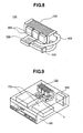
- Fig. 8 is a perspective view of a liquid cooling system, according to a fifth embodiment of the present invention; and
- Fig. 9 is a perspective view of an electronic apparatus, installing therein the liquid cooling system according to the fifth embodiment mentioned above.
-
- Hereinafter, embodiments according to the present invention will be fully explained, sequentially, by referring to the attached drawings.
- Explanation will be made on the first embodiment of the present invention, by referring to Figs. 1-3.
- Figs. 1 (a) to 1 (c) are views, including a perspective view of a liquid cooling jacket applying the first embodiment therein and the cross-section views of each part thereof.
- Fig. 2 is a front view for showing the configuration of a lamination plates, building up the liquid cooling jacket shown in Figs. 1(a) to 1(c).
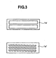
- Fig. 3 is a view corresponding to Fig. 2 mentioned above, for explaining a variation of the lamination plates.
- In Figs. 1(a) to 1(c), the
liquid cooling jacket 100, according to the present embodiment, is made up by bondinglamination plates lamination plates flow passages 8 of a cooling liquid. On both ends of thelamination plates side end plates 15. Also, at one end of thelamination plates end plate 16 is attached thereto. Thisend plate 16 defines a portion where aninlet portion 6 and anoutlet portion 7 are formed for the cooling liquid. - This
liquid cooling jacket 100 is thermally connected with asemiconductor module 5, through aheat conduction member 4. - After piling up the
lamination plates side end plates 15, and further attached with theend plate 16 forming the inlet/outlet portions at the one end of thelamination plates liquid cooling jacket 100 through brazing them, as a whole. - In this
liquid cooling jacket 100, the cooling liquid flows within theflow passage 8 defined between thelamination plates lamination plates 1b has a kind of a cooling fin of the function thereof. With such the structure, it is very easy to make thelamination plates - Also, the
lamination plates heat conductionmember 4, it is possible to eliminate an ill influence upon the heat transmission in the direction perpendicular to the base surface of the brazing material having the low heat conductivity thereof. For this reason, it is possible to obtain a low inner thermal resistance corresponding to that, which can obtained through the cutting process of forming a one body taking a high manufacturing cost thereof; therefore, it is possible to obtain very preferable cooling capacity for the sake of asemiconductor module 5. - The
liquid cooling jacket 100 is, basically, made up with only one (1) kind of thelamination plate 1 punched out, and it includes no process therein in need of man-hour, such as, needed in the cutting process, for example; therefore there is a merit that the cost can be reduced down, greatly, which is necessary for manufacturing and processing thereof, comparing to that of the conventional art. It is also possible to keep the thickness of theliquid cooling jacket 100 to be thin in a ratio to the heat conduction area obtained therefrom. - In Fig. 2, the
lamination plate 1a is punched out to be square in the shape thereof, and is put into between therespective lamination plates 1b piled up in a plural number thereof, so as to form a spacer between thelamination plates 1b. Thislamination plates 1b are cut out at a portion opposing to theinlet portion 6 thereof, and this cut-out portion defines an enter portion for a liquid. A portion opposing to this cut-out portion is punched out to be also square in the shape thereof. This punched-out portion defines a passage, through which the liquid moves in the horizontal direction. As was mentioned in the above, since thislamination plate 1b has a large contact area with the cooling liquid, therefore it has a function of, such as, a kind of a cooling fin. Thelamination plate 1c is partitioning thelamination plates lamination plates inlet portion 6 and a group of thelamination plates outlet portion 7. - The
liquid cooling jacket 100, which is built up with such thelamination plates side end plates 15. The cut-out portion of thelamination plate 1b defines the inlet portion and the outlet portion of the cooling liquid, and therefore anend plate 16, on which theinlet portion 6 and theoutlet portion 7 are formed, is attached thereto, so that it covers the cut-out portion. - In Fig. 3, the passages of the cooling liquid is divided into the vertical direction within the
lamination plate 1a'. The passages of the cooling liquid, being divided into the vertical direction in a plural number, are further formed in a waveform-like in the shape thereof, within thelamination plate 1a". - With this, it is possible to bring the flow within the flow passage to be complex, thereby obtaining an improvement on the mechanical strength and/or a promotion on the heat transfer at the fin surface, as well as, thermal conduction within fins thereof.
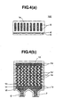
- Fig. 4 (a) is a view of showing the liquid cooling jacket, according to a second embodiment, corresponding to that shown in Fig. 1 mentioned above.
- Fig. 4 (b) is a cross-section view of the liquid cooling jacket, in particular, in a case that it is made up with piling up the lamination plates.
- In Fig. 4(a), differing from that of the first embodiment,
lamination plates 1e are piled up in the depth direction thereof. Moreover, on thislamination plates 1e, a plural number of holes, being also formed through the punching process, are shifted in one (1) direction (in the example shown in Fig. 4 (a), being shifted into the left-hand side), as a whole thereof. And, in the present embodiment, thoselamination plates 1e are piled up, being turned upside down with an each piece thereof. - In other words, since the shifting direction differs from that of the hole formed in each pf the
lamination plates 1e, the flow passage is meandered or zigzagged around. - In Fig. 4(b), a plural number of holes, which are punched out in the
lamination plates 1e, are shifted a little bit with respect to the central shaft thereof, therefore it comes out as shown by 1e' in the figure, when turning thelamination plate 1e piled up next thelamination plate 1e upside down. Repeating the reversing lamination in this manner results into the forming of theflow passage 8 made upwith a large number of overhang orexpansive portions 14 therein. - In the present embodiment, a main body of the
liquid cooling jacket 100 is formed, through brazing thelamination plates inlet portion 6 and theoutlet portion 7 for the cooling liquid are attached thereon. However, the main body and theinlet portion 6 and theoutlet portion 7 for the cooling liquid may be formed in one body, also through the brazing. - A lower surface of the
liquid cooling jacket 100 is connected with an upper surface of thesemiconductor module 5, thermally, through a heat-conductive material having softness. - In such the structure, the cooling liquid flows within the inside of the
flow passage 8 defined by thelamination plates overhand portions 14 functions as a cooling fin, and also it bring the flow of the cooling liquid to be complex, so as to promotes mixture thereof, therefore, it is possible to obtain a preferable cooling capacity or performance. - Also in the present embodiment, the
lamination plates 1 reaches up to the portion of a fin base in contact with the heat-conductive member 4, therefore it is possible to eliminate the ill influence caused upon the heat transmission in the direction perpendicular to the base surface, due to the fact the brazing material has the heat conductivity lower than that of the fin material, comparing thereto. Accordingly, the inner thermal resistance can be obtained; being worth to that which can be obtained by a member of one (1) body, taking much cost for manufacturing thereof. - The
liquid cooling jacket 100, basically, is built up with only one (1) kind of thelamination plate 1 punched out, including no such process in need of man-hour as needed in the cutting process; therefore, it has a merit that the cost necessary for manufacturing and for processing thereof can be reduced down, comparing to that in relation to the conventional arts. And, also, it is possible to maintain theliquid cooling jacket 100 to be thin in the thickness thereof. - Fig. 5 is a view for showing the lamination plates to be applied according to the second embodiment, in which a shape of the hole is altered.
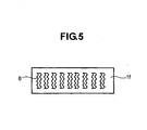
- In this Fig. 5, zigzagging of the holes in the shape, which are formed in the
lamination plate 1f, results in an increase of the heat transfer area in a ratio to the thickness of theliquid cooling jacket 100. Further, reversing upside down when piling up thelamination plates 1 makes the flow within theflow passage 8 very complex, thereby obtaining the heat transfer being very high. For this reason, it is possible to obtain theliquid cooling jacket 100 having a very preferable cooling capacity or performance. - Also, the position of the pouching treated on the each
lamination plate 1 is shifted a little bit from the central axis thereof, as was shown in Fig. 4 mentioned above, and it is piled up reversing upside down, and then theflow passage 8 comes to be complex, much more, and therefore the heat conductivity upon the surface of theflow passage 8 can be increased up to be higher. - Fig. 6 (a) is the cross-sectional view of the liquid cooling jacket, according to a third embodiment.
- Fig. 6(b) is the cross-sectional view of the plates being piled up.
- In Fig. 6(a), the
lamination plates 1 and 1', in each of which the holes are formed in zigzagged manner (or, "S"-like shape) through the punching process, are piled up, one by one, each being reversed upside down. Dotted line in the figure depicts the lamination plates 1' being piled up after being reversed upside down. By means of those zigzag-shaped holes, there is made up theflow passage 8 for the cooling liquid. - The positions of punching out the holes on the
lamination plates 1 are shifted a little bit from the central axis in the horizontal direction, therefore a large number of theoverhang portions 14 are defined within theflow passage 8, when piling up thelamination plates lamination plates 1, 1' in the vertical direction thereof, there are provided anupper end plate 2 and alower end plate 3. And, on theupper end plate 2 are provided theinlet portion 6 and theoutlet portion 7 for the cooling liquid. - With the present embodiment, the main body of the
liquid cooling jacket 100 is built up, through brazing thelamination plates 1 and 1', theupper end plate 2, and thelower end plate 3, as a whole, after filing them up in layers, and thereafter are attached with theinlet portion 6 and theoutlet portion 7 for the cooling liquid thereon. However, it is possible to build up the main body together with theinlet portion 6 and the outlet portion for the cooling liquid, in one body through the brazing. - A lower surface of the
liquid cooling jacket 100 is connected with an upper surface of thesemiconductor module 5, thermally, through a heat-conductive material having softness. - With such the structure, the cooling liquid flows within the
flow passage 8, which is defined between theupper end plate 2 and thelower end plate 3. In this instance, since the large number ofhangover portions 14 are defined within theflow passage 8 so as to function as the cooling fins; therefore, it is possible to obtain a heat transfer area being large in the ratio of the thickness thereof, thereby obtaining a preferable cooling capacity or performance. Theliquid cooling jacket 100, basically, is built up with only one (1) kind of thelamination plate 1 punched out, including no such process in need of man-hour as needed in the cutting process; therefore, it has a merit that the cost necessary manufacturing and process ingthereof can be reduced down, comparing to that in relation to the conventional arts. And, it is also possible to maintain theliquid cooling jacket 100 to be thin in the thickness thereof. - Fig. 7(a) is an upper view of the liquid cooling jacket, according to a fourth embodiment.
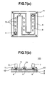
- Fig. 7 (b) is the cross-sectional view of the liquid cooling jacket, according to the fourth embodiment.
- In Fig. 7(a), the
liquid cooling jacket 100, according to the present embodiment, is made up with two (2) pieces of plates, and basically, it is made up with anupper lamination plate 9, which is formed through a press process, and a plate-likelower layer plate 10. In theupper lamination plate 9 is formed theflow passage 8 in a zigzag-like manner (or "S"-like shaped) through extrusion forming obtained by the press process, and further in this extrusion forming portion are formed a plural number ofconcave portions 13. - In Fig. 7(b), the
upper lamination plate 9 and thelower lamination plate 10 are fixed with, throughscrews 11 while putting a packingrubber 12 therebetween. Theinlet portion 6 and theoutlet portion 7 of the cooling liquid are attached on theupper lamination plate 9, so that they are communicated with the flow passage mentioned above. - In this manner, the cooling liquid flows within the
flow passage 8 defined between theupper lamination plate 9 and thelower lamination plate 10. In this instance, due to the function of therecesses 13 provided within theflow passage 9, the cooling liquid repeats meandering therein, thereby being enhanced or promoted on the mixing-up thereof. In this manner, since theflow passage 8 is flat and thin in the shape, and also with provision of the large number ofrecesses 13 thereon, it is possible to obtain a preferable heat conducting capacity or performance. - The
liquid cooling jacket 100, since it includes no such process in need of man-hour as is needed in the cutting process, and further there is no necessity of the process for forming a sealing against leakage of liquid therethrough, such as, the brazing, therefore it brings about a merit that the costs needed for manufacturing and processing can be reduced down, greatly, comparing to the conventional technology. And, also, the thickness of theliquid cooling jacket 100 can be kept to be very thin in the thickness thereof. - Fig. 8 is a perspective view of a liquid cooling system, according to a fifth embodiment.
- In this Fig. 8, a
liquid cooling system 120 is built up with apump 500, aradiator 200, aliquid cooling jacket 100 and afan 300 for use of cooling down the radiator, and alsopipe 400, etc. Into thisliquid cooling system 120 is installed the liquid cooling jacket, which was explained in either one of the embodiments; i.e., from theembodiment 1 toembodiment 4. - Fig. 9 is a perspective view of an electronic apparatus installing the liquid cooling system shown in Fig. 8 mentioned above.
- In this Fig. 9, within the
electronic apparatus 150, other than that, there are provided a large number ofelectronic parts 700 and afan 600 for cooling thereof. In the present embodiment, theradiator 200 and thefan 300 for use of cooling of the radiator are disposed at the most downstream side within ahousing 150 of the electronic apparatus. - By the way, in such the electronic apparatus, because of receiving a large number of electronic parts, etc. , within an inside thereof, a space is limited for installing the
liquid cooling system 12 therein. Accordingly, it has a problem to be dissolved, for such theliquid cooling system 120, to make theradiator 200 being small in the sized thereof, in particular, occupying the space thereof. - However, in general, excepting for a special case, it is impossible to paying a large amount of costs on the liquid cooling system itself. This problem cannot be achiever or dissolved, easily, by only directing the
radiator 200 to be high in the performances or capacity thereof. - Thus, seeing the
liquid cooling system 120 from a viewpoint of the entire thermal balance thereof, normally, the thermal resistance in theliquid cooling jacket 100, which is made up through the conventional manufacturing method, such as, the extrusion forming, for example, comes to be larger than that in theradiator 200. - For this reason, the high-performances or capacity of the radiator cannot be results into an increase of heat radiation, directly, by means of the
radiator 200 itself, seeing from the system, as a whole; therefore it is impossible to reach the remarkable small-sizing thereof. - On the other hand, the
liquid cooling jacket 100, according to the present embodiments, is low on the costs thereof and also in the thermal resistance therein; therefore, an effect of high-performances or capacity of theradiator 200 gives an influence upon an increase of the heat radiation capacity or performance of theradiator 200, directly, seeing from a viewpoint of the thermal balance upon the entirety of theliquid cooling system 120. For this, it is possible to make theradiator 200 to be small in sized thereof, greatly. - With such the structure within an inside of the hosing as shown in Fig. 9 mentioned above, the heat removed from the
semiconductor module 5 having high heat-generation is discharged from theradiator 200 into an inside of thehousing 150, however it faces onto an exit portion, it goes into the atmosphere as it is, but remaining within thehousing 150. For this reason, the flow within the hous ing comes to be very smooth, thereby maintaining the cooling capacity or performance to be preferable, extremely. Also, thefan 300 for use of cooling the radiator also carries out the role of the discharge fan for the entirety of an inside of thehousing 150, it distributes to the cooling of theother parts 700, too. - Though only showing the example, according to the present embodiment, in which the liquid cooling system is installed into a main body of the personal computer, for example, as is shown in Fig. 9 mentioned above, however since the liquid cooling system is compact in the sized as is shown in Fig. 8 mentioned above, therefore the field applicable of thereof is very wide, including the equipments and apparatus, which installs the semiconductor element having heat-generation therein, such as, a plasma television, a game machine, or a liquid crystal projector, etc.
- As was mentioned in the above, according to the present invention, since it is very easy to form the lamination plates to be very thin in the thickness thereof, therefore it is possible to keep a large area for achieving the heat conduction therethrough. Also, the inner thermal resistance is very low, in respect to the heat transmission into the direction perpendicular to the base surface. Due to those effects, it is possible to obtain the cooling capacitor or performance thereof, being very preferable.
- Thus, according to the present invention, it is possible to provide an electronic apparatus having the liquid cooling jacket for use of cooling and the system thereof, enabling promotion on the heat transmission within the flow passage itself.
- The present invention may be embodied in other specific forms without departing from the spirit or essential feature or characteristics thereof. The present embodiment(s) is/are therefore to be considered in all respects as illustrative and not restrictive, the scope of the invention being indicated by the appended claims rather than by the forgoing description and range of equivalency of the claims are therefore to be embraces therein.
Claims (7)
- A liquid cooling system, comprising:a heat-receiving element (4), being thermally connected with a heat-generation part (5);a pump (500) for transporting a liquid to said heat-receiving element; anda radiator (200) for receiving heat from said heat-generation part with an aid of said pump, and for radiating heat of the liquid, wherein:said heat-receiving element (4) is made up with a lamination plate (1), being formed through punching process, and said lamination plate comprises a flow passage, within which the liquid communicates and are provided a plural number of fins.
- The liquid cooling system, as described in the claim 1, wherein:said lamination plate (1) has a first lamination plate (1a) having a hole at a central portion thereof, and a second lamination plate (1b) having an opened cut-out portion at one end thereof and a hole at other thereof, and said first and second lamination plates are piled up alternately, thereby forming a lamination group of an inlet side of the liquid and another lamination group of an outlet side of the liquid.
- The liquid cooling system, as described in the claim 1, wherein:said lamination plate (1e) is made up with metal thin-plates, each having a plural number of holes in a longitudinal direction thereof, being shifted into one side in the longitudinal direction with respect to a central portion thereof, being piled up one by one, while reversing the metal thin-plate upside down.
- The liquid cooling system, as described in the claim 1, wherein:said lamination plate (1f) is made up with metal thin-plates, each having a zigzagging one piece of hole, being shifted into a one side with respect to a central portion thereof, being piled up one by one, while reversing the metal thin-plate upside down.
- The liquid cooling system, as described in the claim 1, wherein:said lamination plate is made up with two pieces of metal plates being laminated vertically, and an upper metal plate (9) of those two metal plates laminated vertically has a one (1) piece of zigzagging groove and a hangover portion, which is formed through extrusion forming within an inside of said groove, and said upper metal plate (9) is fixed on a plate-like lower metal plate (10), putting a sealing member therebetween.
- A liquid cooling system, comprising:a heat-receiving element (4), being thermally connected with a heat-generation part (5);a pump (500) for transporting a liquid to said heat-receiving element (4); anda radiator (200) for receiving heat from said heat-generation part with an aid of said pump, and for radiating heat of the liquid, wherein:said heat-receiving element (4) is made up with a lamination plate (1), being formed through punching process, and said lamination plate comprises a flow passage (8), within which the liquid communicates and are provided a plural number of fins, and further said pump (500) and said radiator (200) are connected with said heat-receiving member through conduits.
- The liquid cooling system, as described in the claim 6, wherein:a fin is attached onto said radiator (200).
Applications Claiming Priority (2)
| Application Number | Priority Date | Filing Date | Title |
|---|---|---|---|
| JP2003402369 | 2003-12-02 | ||
| JP2003402369A JP2005166855A (en) | 2003-12-02 | 2003-12-02 | Electronic apparatus |
Publications (3)
| Publication Number | Publication Date |
|---|---|
| EP1538884A2 true EP1538884A2 (en) | 2005-06-08 |
| EP1538884A3 EP1538884A3 (en) | 2005-10-12 |
| EP1538884B1 EP1538884B1 (en) | 2010-05-26 |
Family
ID=34463949
Family Applications (1)
| Application Number | Title | Priority Date | Filing Date |
|---|---|---|---|
| EP04005163A Expired - Fee Related EP1538884B1 (en) | 2003-12-02 | 2004-03-04 | Liquid cooling system for use in an electronic apparatus |
Country Status (7)
| Country | Link |
|---|---|
| US (1) | US7044198B2 (en) |
| EP (1) | EP1538884B1 (en) |
| JP (1) | JP2005166855A (en) |
| KR (1) | KR100612810B1 (en) |
| CN (1) | CN100386872C (en) |
| DE (1) | DE602004027341D1 (en) |
| TW (1) | TWI255025B (en) |
Cited By (4)
| Publication number | Priority date | Publication date | Assignee | Title |
|---|---|---|---|---|
| WO2006010822A2 (en) * | 2004-06-24 | 2006-02-02 | TECHNOLOGIES DE L'ECHANGE THERMIQUE Société Anonyme Simplifiée | Improved cooling devices for different applications |
| FR2880107A1 (en) * | 2004-12-27 | 2006-06-30 | Technologies De L Echange Ther | Water cooling device for motor vehicle, has integral radiator provided with thin-walled and hollow fins, and with manifolds connected to manifolds of original component that is formed by mini heater |
| CN103298317A (en) * | 2012-02-24 | 2013-09-11 | 三菱电机株式会社 | Cooler and cooling device |
| EP2582213B1 (en) * | 2010-06-09 | 2021-01-20 | Kyocera Corporation | Flow channel member, heat exchanger using same, and electronic component device |
Families Citing this family (35)
| Publication number | Priority date | Publication date | Assignee | Title |
|---|---|---|---|---|
| US7327571B2 (en) * | 2005-09-06 | 2008-02-05 | Hewlett-Packard Development Company, L.P. | Thermal load balancing systems and methods |
| JP4682775B2 (en) * | 2005-09-27 | 2011-05-11 | セイコーエプソン株式会社 | Microchannel structure, heat exchange system, and electronic device |
| JP2007127398A (en) | 2005-10-05 | 2007-05-24 | Seiko Epson Corp | Heat exchanger, method of manufacturing heat exchanger, liquid cooling system, light source device, projector, electronic device unit, and electronic apparatus |
| JP4449894B2 (en) | 2005-12-16 | 2010-04-14 | セイコーエプソン株式会社 | Heat exchanger, light source device, projector and electronic device |
| JP4645472B2 (en) * | 2006-02-21 | 2011-03-09 | セイコーエプソン株式会社 | Fluid cooling device and electronic device |
| US7537047B2 (en) | 2006-03-23 | 2009-05-26 | Foxconn Technology Co., Ltd. | Liquid-cooling heat sink |
| CN100584169C (en) * | 2006-04-21 | 2010-01-20 | 富准精密工业(深圳)有限公司 | Liquid-cooled heat radiator |
| JP2008027374A (en) * | 2006-07-25 | 2008-02-07 | Fujitsu Ltd | Heat receiver for liquid cooling unit, liquid cooling unit, and electronic device |
| JP4842040B2 (en) | 2006-07-25 | 2011-12-21 | 富士通株式会社 | Electronics |
| JP5283836B2 (en) | 2006-07-25 | 2013-09-04 | 富士通株式会社 | Heat receiver and liquid cooling unit for liquid cooling unit and electronic device |
| JP5148079B2 (en) * | 2006-07-25 | 2013-02-20 | 富士通株式会社 | Heat exchanger for liquid cooling unit, liquid cooling unit and electronic equipment |
| JP4781929B2 (en) | 2006-07-25 | 2011-09-28 | 富士通株式会社 | Electronics |
| JP5133531B2 (en) * | 2006-07-25 | 2013-01-30 | 富士通株式会社 | Heat exchanger for liquid cooling unit, liquid cooling unit and electronic equipment |
| JP2008027370A (en) | 2006-07-25 | 2008-02-07 | Fujitsu Ltd | Electronic device |
| JP5005314B2 (en) * | 2006-10-17 | 2012-08-22 | 株式会社ティラド | Water-cooled heat sink and manufacturing method thereof |
| US9943014B2 (en) | 2013-03-15 | 2018-04-10 | Coolit Systems, Inc. | Manifolded heat exchangers and related systems |
| US9496200B2 (en) | 2011-07-27 | 2016-11-15 | Coolit Systems, Inc. | Modular heat-transfer systems |
| CN101610664B (en) * | 2008-06-20 | 2014-05-14 | 萨帕铝型材(上海)有限公司 | Liquid cooler and manufacture method thereof |
| JP2011017516A (en) * | 2009-07-10 | 2011-01-27 | Mitsubishi Electric Corp | Plate laminated type cooling device and method of manufacturing the same |
| JP5259559B2 (en) * | 2009-11-30 | 2013-08-07 | 株式会社ティラド | heatsink |
| WO2011136362A1 (en) * | 2010-04-28 | 2011-11-03 | 株式会社 豊田自動織機 | Heat dissipation device and semiconductor device |
| CN102647884B (en) * | 2011-02-17 | 2015-03-18 | 北汽福田汽车股份有限公司 | Radiator and heat radiation water channel system structure thereof |
| JP6005930B2 (en) * | 2011-07-28 | 2016-10-12 | 京セラ株式会社 | Channel member, heat exchanger using the same, electronic component device, and semiconductor manufacturing device |
| US10365667B2 (en) | 2011-08-11 | 2019-07-30 | Coolit Systems, Inc. | Flow-path controllers and related systems |
| WO2014141162A1 (en) | 2013-03-15 | 2014-09-18 | Coolit Systems, Inc. | Sensors, multiplexed communication techniques, and related systems |
| US20130058043A1 (en) * | 2011-09-03 | 2013-03-07 | Weiss-Aug Co. Inc | Heat sink with a stack of metal layers having channels therein |
| US9275931B2 (en) * | 2012-01-12 | 2016-03-01 | Huang-Han Chen | Heat dissipating module |
| KR101524939B1 (en) * | 2013-11-06 | 2015-06-02 | 주식회사 동양매직 | a water jacket for cooling heating unit and a cooling tank comprising the same |
| WO2017098640A1 (en) * | 2015-12-10 | 2017-06-15 | 株式会社日立製作所 | Shaped article, electronic equipment, and shaping method |
| US10251306B2 (en) * | 2016-09-26 | 2019-04-02 | Asia Vital Components Co., Ltd. | Water cooling heat dissipation structure |
| CN106711110B (en) * | 2017-03-19 | 2019-05-17 | 北京工业大学 | A kind of air-cooled water cooling mixing heat radiation module for high-power series IGBT |
| US11662037B2 (en) | 2019-01-18 | 2023-05-30 | Coolit Systems, Inc. | Fluid flow control valve for fluid flow systems, and methods |
| US11473860B2 (en) | 2019-04-25 | 2022-10-18 | Coolit Systems, Inc. | Cooling module with leak detector and related systems |
| US11395443B2 (en) | 2020-05-11 | 2022-07-19 | Coolit Systems, Inc. | Liquid pumping units, and related systems and methods |
| KR102449766B1 (en) * | 2022-03-18 | 2022-10-04 | 덕양산업 주식회사 | Cooling plate for battery module |
Citations (6)
| Publication number | Priority date | Publication date | Assignee | Title |
|---|---|---|---|---|
| US4705102A (en) * | 1985-12-13 | 1987-11-10 | Fuji Electric Company, Ltd. | Boiling refrigerant-type cooling system |
| JPH09102568A (en) * | 1995-10-05 | 1997-04-15 | Mitsubishi Electric Corp | Plate type heat sink |
| US5832989A (en) * | 1996-03-14 | 1998-11-10 | Denso Corporation | Cooling apparatus using boiling and condensing refrigerant |
| US20010004370A1 (en) * | 1998-08-18 | 2001-06-21 | Hamamatsu Photonics K.K. | Heat sink and semiconductor laser apparatus and semiconductor laser stack apparatus using the same |
| EP1244145A2 (en) * | 2001-03-20 | 2002-09-25 | Motorola, Inc. | Press formed two-phase cooling module and method for making same |
| US20020135979A1 (en) * | 2001-03-20 | 2002-09-26 | Motorola, Inc | Two-phase cooling module and method of making the same |
Family Cites Families (13)
| Publication number | Priority date | Publication date | Assignee | Title |
|---|---|---|---|---|
| US4468717A (en) * | 1982-06-09 | 1984-08-28 | Sperry Corporation | Apparatus for cooling integrated circuit chips |
| CA1227886A (en) * | 1984-01-26 | 1987-10-06 | Haruhiko Yamamoto | Liquid-cooling module system for electronic circuit components |
| US4561040A (en) * | 1984-07-12 | 1985-12-24 | Ibm Corporation | Cooling system for VLSI circuit chips |
| US4910642A (en) * | 1988-12-05 | 1990-03-20 | Sundstrand Corporation | Coolant activated contact compact high intensity cooler |
| US5125451A (en) * | 1991-04-02 | 1992-06-30 | Microunity Systems Engineering, Inc. | Heat exchanger for solid-state electronic devices |
| FR2701554B1 (en) * | 1993-02-12 | 1995-05-12 | Transcal | Heat exchanger for electronic components and electro-technical equipment. |
| US6152213A (en) * | 1997-03-27 | 2000-11-28 | Fujitsu Limited | Cooling system for electronic packages |
| US5815370A (en) * | 1997-05-16 | 1998-09-29 | Allied Signal Inc | Fluidic feedback-controlled liquid cooling module |
| US6152215A (en) * | 1998-12-23 | 2000-11-28 | Sundstrand Corporation | High intensity cooler |
| US6166907A (en) * | 1999-11-26 | 2000-12-26 | Chien; Chuan-Fu | CPU cooling system |
| JP4423792B2 (en) * | 2000-09-14 | 2010-03-03 | 株式会社デンソー | Boiling cooler |
| JP2003007944A (en) * | 2001-06-18 | 2003-01-10 | Showa Denko Kk | Cooling device for heating part |
| CN2577220Y (en) * | 2002-09-27 | 2003-10-01 | 天津市吉鑫达金属制品有限公司 | Special-shaped-tube radiator with decorative edge |
-
2003
- 2003-12-02 JP JP2003402369A patent/JP2005166855A/en not_active Withdrawn
-
2004
- 2004-02-23 TW TW093104461A patent/TWI255025B/en not_active IP Right Cessation
- 2004-03-03 KR KR1020040014159A patent/KR100612810B1/en active IP Right Grant
- 2004-03-04 EP EP04005163A patent/EP1538884B1/en not_active Expired - Fee Related
- 2004-03-04 DE DE602004027341T patent/DE602004027341D1/en not_active Expired - Lifetime
- 2004-03-05 CN CNB2004100077654A patent/CN100386872C/en not_active Expired - Fee Related
- 2004-03-05 US US10/792,690 patent/US7044198B2/en not_active Expired - Lifetime
Patent Citations (6)
| Publication number | Priority date | Publication date | Assignee | Title |
|---|---|---|---|---|
| US4705102A (en) * | 1985-12-13 | 1987-11-10 | Fuji Electric Company, Ltd. | Boiling refrigerant-type cooling system |
| JPH09102568A (en) * | 1995-10-05 | 1997-04-15 | Mitsubishi Electric Corp | Plate type heat sink |
| US5832989A (en) * | 1996-03-14 | 1998-11-10 | Denso Corporation | Cooling apparatus using boiling and condensing refrigerant |
| US20010004370A1 (en) * | 1998-08-18 | 2001-06-21 | Hamamatsu Photonics K.K. | Heat sink and semiconductor laser apparatus and semiconductor laser stack apparatus using the same |
| EP1244145A2 (en) * | 2001-03-20 | 2002-09-25 | Motorola, Inc. | Press formed two-phase cooling module and method for making same |
| US20020135979A1 (en) * | 2001-03-20 | 2002-09-26 | Motorola, Inc | Two-phase cooling module and method of making the same |
Non-Patent Citations (1)
| Title |
|---|
| PATENT ABSTRACTS OF JAPAN vol. 1997, no. 08, 29 August 1997 (1997-08-29) & JP 09 102568 A (MITSUBISHI ELECTRIC CORP), 15 April 1997 (1997-04-15) * |
Cited By (6)
| Publication number | Priority date | Publication date | Assignee | Title |
|---|---|---|---|---|
| WO2006010822A2 (en) * | 2004-06-24 | 2006-02-02 | TECHNOLOGIES DE L'ECHANGE THERMIQUE Société Anonyme Simplifiée | Improved cooling devices for different applications |
| WO2006010822A3 (en) * | 2004-06-24 | 2006-05-11 | Technologies De L Echange Ther | Improved cooling devices for different applications |
| FR2880107A1 (en) * | 2004-12-27 | 2006-06-30 | Technologies De L Echange Ther | Water cooling device for motor vehicle, has integral radiator provided with thin-walled and hollow fins, and with manifolds connected to manifolds of original component that is formed by mini heater |
| EP2582213B1 (en) * | 2010-06-09 | 2021-01-20 | Kyocera Corporation | Flow channel member, heat exchanger using same, and electronic component device |
| CN103298317A (en) * | 2012-02-24 | 2013-09-11 | 三菱电机株式会社 | Cooler and cooling device |
| CN103298317B (en) * | 2012-02-24 | 2016-03-02 | 三菱电机株式会社 | Cooler and cooling device |
Also Published As
| Publication number | Publication date |
|---|---|
| US20050126752A1 (en) | 2005-06-16 |
| JP2005166855A (en) | 2005-06-23 |
| DE602004027341D1 (en) | 2010-07-08 |
| CN100386872C (en) | 2008-05-07 |
| KR20050053298A (en) | 2005-06-08 |
| EP1538884A3 (en) | 2005-10-12 |
| US7044198B2 (en) | 2006-05-16 |
| CN1624407A (en) | 2005-06-08 |
| TW200520187A (en) | 2005-06-16 |
| TWI255025B (en) | 2006-05-11 |
| EP1538884B1 (en) | 2010-05-26 |
| KR100612810B1 (en) | 2006-08-18 |
Similar Documents
| Publication | Publication Date | Title |
|---|---|---|
| US7044198B2 (en) | Electronic apparatus | |
| US6422307B1 (en) | Ultra high fin density heat sink for electronics cooling | |
| US7516777B2 (en) | Cooling jacket | |
| EP1790007B1 (en) | Micro-structured cooler and use thereof | |
| US6729389B2 (en) | Heat transfer apparatus with zigzag passage | |
| US7017655B2 (en) | Forced fluid heat sink | |
| US6986382B2 (en) | Interwoven manifolds for pressure drop reduction in microchannel heat exchangers | |
| US6988534B2 (en) | Method and apparatus for flexible fluid delivery for cooling desired hot spots in a heat producing device | |
| US6634421B2 (en) | High performance cold plate for electronic cooling | |
| US6431260B1 (en) | Cavity plate and jet nozzle assemblies for use in cooling an electronic module, and methods of fabrication thereof | |
| EP1276362B1 (en) | Flattened tube cold plate for liquid cooling electrical components | |
| CN101610664B (en) | Liquid cooler and manufacture method thereof | |
| US8561673B2 (en) | Sealed self-contained fluidic cooling device | |
| EP1564809A1 (en) | Liquid cooling system and electronic apparatus comprising that system | |
| EP3742097B1 (en) | Water block assembly | |
| WO1997015801A1 (en) | Liquid cooled heat sink for cooling electronic components | |
| WO2006115073A1 (en) | Liquid-cooled jacket | |
| US11175102B1 (en) | Liquid-cooled cold plate | |
| CN102456938A (en) | Battery thermal system with interlocking structure components | |
| US11732978B2 (en) | Laminated microchannel heat exchangers | |
| US20230296332A1 (en) | Reduced pressure drop cold plate transition | |
| WO1995017765A2 (en) | Liquid cooled heat sink for cooling electronic components | |
| WO2017184635A1 (en) | Laminated microchannel heat exchangers | |
| JPH10308486A (en) | Boiling cooler and its manufacture | |
| JP2018032744A (en) | Semiconductor device |
Legal Events
| Date | Code | Title | Description |
|---|---|---|---|
| PUAI | Public reference made under article 153(3) epc to a published international application that has entered the european phase |
Free format text: ORIGINAL CODE: 0009012 |
|
| AK | Designated contracting states |
Kind code of ref document: A2 Designated state(s): AT BE BG CH CY CZ DE DK EE ES FI FR GB GR HU IE IT LI LU MC NL PL PT RO SE SI SK TR |
|
| AX | Request for extension of the european patent |
Extension state: AL LT LV MK |
|
| PUAL | Search report despatched |
Free format text: ORIGINAL CODE: 0009013 |
|
| AK | Designated contracting states |
Kind code of ref document: A3 Designated state(s): AT BE BG CH CY CZ DE DK EE ES FI FR GB GR HU IE IT LI LU MC NL PL PT RO SE SI SK TR |
|
| AX | Request for extension of the european patent |
Extension state: AL LT LV MK |
|
| 17P | Request for examination filed |
Effective date: 20060203 |
|
| AKX | Designation fees paid |
Designated state(s): DE |
|
| 17Q | First examination report despatched |
Effective date: 20080423 |
|
| GRAP | Despatch of communication of intention to grant a patent |
Free format text: ORIGINAL CODE: EPIDOSNIGR1 |
|
| GRAS | Grant fee paid |
Free format text: ORIGINAL CODE: EPIDOSNIGR3 |
|
| GRAA | (expected) grant |
Free format text: ORIGINAL CODE: 0009210 |
|
| RIN1 | Information on inventor provided before grant (corrected) |
Inventor name: SUZUKI, OSAMU,C Inventor name: TAKEUCHI, TSUNENORI,C Inventor name: ASANO, ICHIROU,C Inventor name: MATSUSHITA, SHINJI,C Inventor name: MATSUSHIMA, HITOSHI,C |
|
| AK | Designated contracting states |
Kind code of ref document: B1 Designated state(s): DE |
|
| REF | Corresponds to: |
Ref document number: 602004027341 Country of ref document: DE Date of ref document: 20100708 Kind code of ref document: P |
|
| PLBE | No opposition filed within time limit |
Free format text: ORIGINAL CODE: 0009261 |
|
| STAA | Information on the status of an ep patent application or granted ep patent |
Free format text: STATUS: NO OPPOSITION FILED WITHIN TIME LIMIT |
|
| 26N | No opposition filed |
Effective date: 20110301 |
|
| REG | Reference to a national code |
Ref country code: DE Ref legal event code: R097 Ref document number: 602004027341 Country of ref document: DE Effective date: 20110228 |
|
| REG | Reference to a national code |
Ref country code: DE Ref legal event code: R082 Ref document number: 602004027341 Country of ref document: DE Representative=s name: MERH-IP MATIAS ERNY REICHL HOFFMANN, DE |
|
| REG | Reference to a national code |
Ref country code: DE Ref legal event code: R081 Ref document number: 602004027341 Country of ref document: DE Owner name: HITACHI MAXELL, LTD., IBARAKI-SHI, JP Free format text: FORMER OWNER: HITACHI, LTD., TOKYO, JP Effective date: 20130604 Ref country code: DE Ref legal event code: R082 Ref document number: 602004027341 Country of ref document: DE Representative=s name: MERH-IP MATIAS ERNY REICHL HOFFMANN PATENTANWA, DE Effective date: 20130604 Ref country code: DE Ref legal event code: R081 Ref document number: 602004027341 Country of ref document: DE Owner name: HITACHI CONSUMER ELECTRONICS CO., LTD., JP Free format text: FORMER OWNER: HITACHI, LTD., TOKYO, JP Effective date: 20130604 Ref country code: DE Ref legal event code: R082 Ref document number: 602004027341 Country of ref document: DE Representative=s name: MERH-IP MATIAS ERNY REICHL HOFFMANN, DE Effective date: 20130604 Ref country code: DE Ref legal event code: R081 Ref document number: 602004027341 Country of ref document: DE Owner name: MAXELL, LTD., OYAMAZAKI, JP Free format text: FORMER OWNER: HITACHI, LTD., TOKYO, JP Effective date: 20130604 |
|
| REG | Reference to a national code |
Ref country code: DE Ref legal event code: R082 Ref document number: 602004027341 Country of ref document: DE Representative=s name: MERH-IP MATIAS ERNY REICHL HOFFMANN, DE |
|
| REG | Reference to a national code |
Ref country code: DE Ref legal event code: R082 Ref document number: 602004027341 Country of ref document: DE Representative=s name: MERH-IP MATIAS ERNY REICHL HOFFMANN, DE Effective date: 20150317 Ref country code: DE Ref legal event code: R081 Ref document number: 602004027341 Country of ref document: DE Owner name: HITACHI MAXELL, LTD., IBARAKI-SHI, JP Free format text: FORMER OWNER: HITACHI CONSUMER ELECTRONICS CO., LTD., TOKIO/TOKYO, JP Effective date: 20150317 Ref country code: DE Ref legal event code: R082 Ref document number: 602004027341 Country of ref document: DE Representative=s name: MERH-IP MATIAS ERNY REICHL HOFFMANN PATENTANWA, DE Effective date: 20150317 Ref country code: DE Ref legal event code: R081 Ref document number: 602004027341 Country of ref document: DE Owner name: MAXELL, LTD., OYAMAZAKI, JP Free format text: FORMER OWNER: HITACHI CONSUMER ELECTRONICS CO., LTD., TOKIO/TOKYO, JP Effective date: 20150317 |
|
| REG | Reference to a national code |
Ref country code: DE Ref legal event code: R082 Ref document number: 602004027341 Country of ref document: DE Representative=s name: MERH-IP MATIAS ERNY REICHL HOFFMANN PATENTANWA, DE Ref country code: DE Ref legal event code: R081 Ref document number: 602004027341 Country of ref document: DE Owner name: MAXELL, LTD., OYAMAZAKI, JP Free format text: FORMER OWNER: HITACHI MAXELL, LTD., IBARAKI-SHI, OSAKA, JP |
|
| PGFP | Annual fee paid to national office [announced via postgrant information from national office to epo] |
Ref country code: DE Payment date: 20210319 Year of fee payment: 18 |
|
| REG | Reference to a national code |
Ref country code: DE Ref legal event code: R081 Ref document number: 602004027341 Country of ref document: DE Owner name: MAXELL, LTD., OYAMAZAKI, JP Free format text: FORMER OWNER: MAXELL, LTD., OYAMAZAKI, KYOTO, JP |
|
| REG | Reference to a national code |
Ref country code: DE Ref legal event code: R081 Ref document number: 602004027341 Country of ref document: DE Owner name: MAXELL, LTD., OYAMAZAKI, JP Free format text: FORMER OWNER: MAXELL HOLDINGS, LTD., OYAMAZAKI, KYOTO, JP |
|
| REG | Reference to a national code |
Ref country code: DE Ref legal event code: R119 Ref document number: 602004027341 Country of ref document: DE |
|
| PG25 | Lapsed in a contracting state [announced via postgrant information from national office to epo] |
Ref country code: DE Free format text: LAPSE BECAUSE OF NON-PAYMENT OF DUE FEES Effective date: 20221001 |