EP1276362B1 - Flattened tube cold plate for liquid cooling electrical components - Google Patents
Flattened tube cold plate for liquid cooling electrical components Download PDFInfo
- Publication number
- EP1276362B1 EP1276362B1 EP02015796A EP02015796A EP1276362B1 EP 1276362 B1 EP1276362 B1 EP 1276362B1 EP 02015796 A EP02015796 A EP 02015796A EP 02015796 A EP02015796 A EP 02015796A EP 1276362 B1 EP1276362 B1 EP 1276362B1
- Authority
- EP
- European Patent Office
- Prior art keywords
- cold plate
- fins
- tube
- flattened tube
- flattened
- Prior art date
- Legal status (The legal status is an assumption and is not a legal conclusion. Google has not performed a legal analysis and makes no representation as to the accuracy of the status listed.)
- Expired - Lifetime
Links
Images


Classifications
-
- H—ELECTRICITY
- H01—ELECTRIC ELEMENTS
- H01L—SEMICONDUCTOR DEVICES NOT COVERED BY CLASS H10
- H01L23/00—Details of semiconductor or other solid state devices
- H01L23/34—Arrangements for cooling, heating, ventilating or temperature compensation ; Temperature sensing arrangements
- H01L23/36—Selection of materials, or shaping, to facilitate cooling or heating, e.g. heatsinks
- H01L23/367—Cooling facilitated by shape of device
-
- H—ELECTRICITY
- H01—ELECTRIC ELEMENTS
- H01L—SEMICONDUCTOR DEVICES NOT COVERED BY CLASS H10
- H01L23/00—Details of semiconductor or other solid state devices
- H01L23/34—Arrangements for cooling, heating, ventilating or temperature compensation ; Temperature sensing arrangements
- H01L23/46—Arrangements for cooling, heating, ventilating or temperature compensation ; Temperature sensing arrangements involving the transfer of heat by flowing fluids
- H01L23/473—Arrangements for cooling, heating, ventilating or temperature compensation ; Temperature sensing arrangements involving the transfer of heat by flowing fluids by flowing liquids
-
- H—ELECTRICITY
- H05—ELECTRIC TECHNIQUES NOT OTHERWISE PROVIDED FOR
- H05K—PRINTED CIRCUITS; CASINGS OR CONSTRUCTIONAL DETAILS OF ELECTRIC APPARATUS; MANUFACTURE OF ASSEMBLAGES OF ELECTRICAL COMPONENTS
- H05K7/00—Constructional details common to different types of electric apparatus
- H05K7/20—Modifications to facilitate cooling, ventilating, or heating
-
- H—ELECTRICITY
- H01—ELECTRIC ELEMENTS
- H01L—SEMICONDUCTOR DEVICES NOT COVERED BY CLASS H10
- H01L2924/00—Indexing scheme for arrangements or methods for connecting or disconnecting semiconductor or solid-state bodies as covered by H01L24/00
- H01L2924/0001—Technical content checked by a classifier
- H01L2924/0002—Not covered by any one of groups H01L24/00, H01L24/00 and H01L2224/00
-
- Y—GENERAL TAGGING OF NEW TECHNOLOGICAL DEVELOPMENTS; GENERAL TAGGING OF CROSS-SECTIONAL TECHNOLOGIES SPANNING OVER SEVERAL SECTIONS OF THE IPC; TECHNICAL SUBJECTS COVERED BY FORMER USPC CROSS-REFERENCE ART COLLECTIONS [XRACs] AND DIGESTS
- Y10—TECHNICAL SUBJECTS COVERED BY FORMER USPC
- Y10T—TECHNICAL SUBJECTS COVERED BY FORMER US CLASSIFICATION
- Y10T29/00—Metal working
- Y10T29/49—Method of mechanical manufacture
- Y10T29/4935—Heat exchanger or boiler making
- Y10T29/49377—Tube with heat transfer means
- Y10T29/49378—Finned tube
- Y10T29/49385—Made from unitary workpiece, i.e., no assembly
-
- Y—GENERAL TAGGING OF NEW TECHNOLOGICAL DEVELOPMENTS; GENERAL TAGGING OF CROSS-SECTIONAL TECHNOLOGIES SPANNING OVER SEVERAL SECTIONS OF THE IPC; TECHNICAL SUBJECTS COVERED BY FORMER USPC CROSS-REFERENCE ART COLLECTIONS [XRACs] AND DIGESTS
- Y10—TECHNICAL SUBJECTS COVERED BY FORMER USPC
- Y10T—TECHNICAL SUBJECTS COVERED BY FORMER US CLASSIFICATION
- Y10T29/00—Metal working
- Y10T29/49—Method of mechanical manufacture
- Y10T29/4935—Heat exchanger or boiler making
- Y10T29/49391—Tube making or reforming
Definitions
- liquids can be used to provide significantly improved cooling, but provisions must be made to contain the liquid so that the electronic components are not directly contacted by the liquid.
- liquid-cooled plate One conventional technique for cooling electronic components uses a liquid-cooled plate.
- Conventional liquid-cooled cold plates are typically made of copper or aluminum, although other materials can be used.
- the cold plate includes channels within it for distributing the cooling liquid, and inlets and outlets for enabling the liquid to enter and exit the cold plate.
- the cold plate is then mated to the electronic circuit board.
- the electrical components on the circuit board that touch the cold plate are thereby cooled because of their close proximity to the cooling liquid, but at no time do the electrical components actually touch the cooling liquid directly.
- Lower performance cold plates typically use metal tubes to distribute the liquid and higher performance cold plates typically use vacuum braze construction.
- Vacuum brazing allows the use of high performance fins to be placed within the liquid channel at locations where better heat transfer is required by the cold plate surface.
- DE 198 13 532 C1 discloses the use of a plate-shaped cooler which is sandwiched between upper and lower contact plates which are cooled by the cooler.
- the present invention provides for cost effective cooling for individual components as well as for entire circuit boards.
- the present invention is directed to providing a cold plate as defined in claim 1 and in claim 14 that efficiently and cost effectively cools electrical components.
- the present invention is accomplished by providing a flattened tube formed from a circular extruded tube to have a top surface and a bottom surface that are substantially parallel and contiguously connected by rounded corners and defining an interior space.
- the circular extruded tube includes a plurality of fins extending into the interior space form inner walls thereof to form a plurality of channels in said flattened tube between said fins for defining a cooling liquid passage therethrough.
- At least one of the top and bottom surfaces of the flattened tube comprises, in a preferred embodiment, fixing means for receiving the electrical components.
- First and second header tubes are connected to opposite edges of the flattened tube for connecting the channels of the flattened tube. Thereby, an inlet and an outlet are provided for passing the cooling liquid through the channels.
- the circular extruded tube may be formed of copper so that water may be used as the cooling liquid without the need for any corrosion inhibitors.
- the fins extend parallel to the direction that the flattened tube extends.
- the fins extend at a predetermined angle to the direction that the flattened tube extends.
- the fins associated with the top surface may extend at an angle to the fins associated with the bottom surface to form a plurality of intersecting points which form a torturous fluid flow path.
- the present invention is further directed to a method as defined in claim 14 of forming a cold plate for liquid cooling electrical components.
- the method includes the steps of extruding metal in a circular tube comprising a plurality of fins extending from the interior surface of the tube with the fins being equally spaced and of a predetermined height. Then, the circularly extruded tube is flattened so that a top surface and a bottom surface are substantially parallel and contiguously connected by rounded corners and the fins extend into the interior between the top and bottom surfaces. Fixing means are attached to at least are of the top and bottom surfaces of the flattened tube, in a preferred embodiment, for receiving the electrical components. As a result, an a cost effective cold plate may be processed that efficiently cools electrical components associated therewith.
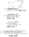
- a cold plate 100 for liquid cooling of electronic components is illustrated in Figs. 1(a) and 1(b).
- the cold plate 100 includes a top surface 120 and a bottom surface 130 that are substantially parallel and contiguously connected by rounded corners 122 and 124.
- a plurality of fins 110 extend substantially perpendicular between the top and bottom surfaces to form a plurality of channels 140 through the length of the cold plate 100.
- the fins may extend straight or spiral/twist down the length of the tube in this embodiment.
- the cold plate 100 copper, aluminum or other like materials or compositions can be extruded into flattened tubes containing the plurality of fins 110. Because the cold plate 100 is formed from copper tubes, or other formable conductors, in an extrusion process, the manufacturing process is very cost effective. Also, the cold plate 100 of the present embodiment will have a thermal performance similar to cold plates formed of a vacuum-brazed process because the fins 110 are very thin walls. However, the cold plate 100 of the present embodiment is manufactured at a fraction of the cost of the vacuum-brazed cold plates. The flattened tube structure of the cold plate 100 is also extremely strong and can sustain internal pressures on the order of approximately 1000 psi or more.
- the internal fins 110 act as spacers which prevents the tube from buckling and the passage from collapsing.
- the cold plate 100 may be bent and shaped for placement in small and tight cooling areas. For instance, the cold plate 100 may be bent at a sharp radius and placed in an area near a motor to cool electrical components.
- header tubes 150 and 152 are connected as manifolds in the openings to the ends of the cold plate 100 as illustrated in the examples of Figs. 2(a) and 2(b).
- the header tubes 150 and 152 are attached by either gluing, soldering, brazing, welding or other known attaching techniques.
- one cold plate 100 is connected between the header tubes 150 and 152 and in the embodiment of Fig. 2(b), five cold plates 100 1 -100 5 are connected between the header tubes 150 and 152 with any more number possible.
- electrical components are directly attached to the top surface of the cold plate 100 by glue, epoxy or other known adhesives.
- screw attachments 170 are attached to the top surface of the cold plate 100 as illustrated in Fig. 3 so that the electrical components can be conveniently attached and removed as necessary.
- the screw attachments 170 are stud welded directly to the top surface of the cold plate 100 so that the electrical components have a receptacle for attachment and removal.
- the screw attachments 170 may be of aluminum, copper or other like materials and compositions.
- the cold plate 100 may be formed of flattened tubes made in a variety of different widths. For instance, flattened tubes of widths ranging from 1.6 inches to 2.0 inches have been manufactured and shown to be of sufficient widths for many applications. However, it is possible to produce the cold plates 100 from flattened tubes having widths of 6 inches and greater if necessary.
- the flattened tubes may be made from aluminum, copper, and like metals and composites.
- copper tubing is preferred over aluminum because of its advantageous characteristics such as better thermal conductivity than aluminum.
- copper is a more suitable material when using water as a cooling fluid because aluminum corrodes in the presence of water.
- well known and commercially available corrosion inhibitors such as ethylene glycol mixtures, must be added to the water.
- well known and commercially available anticorrosion fluids such as hi-dielectric fluids, are used in place of the water/corrosion inhibitor mixtures in place of water.
- the fins 110 may be spaced further apart to provide wider channels 140 because water provides excellent heat transfer characteristics.
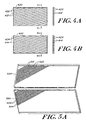
- FIGs. 4(a) and 4(b) illustrate an example of a top section and a bottom section 420 and 430 respectively of a cold plate having angled fins 412 and 414 according to an embodiment of the present invention. When the top and bottom sections are superimposed on one another, the angled fins cross one another and provide angled fluid flow paths through channels 422 and 424 which greatly enhances the heat transfer.
- Fig. 5(a) illustrates the geometry formed of the angled fins 512 and 514 on the top and bottom sections 520 and 530 respectively and Fig.
- FIG. 5(b) illustrates an isometric view of the internal passages of the cold plate according to the present embodiment.
- the thickness and length of the fins as well as the intersection angle of the fins may vary based on the desired application of the cold plate.
- the walls of the fins may be easily tailored to be thin or thick, and spaced closely or widely depending on the particular application.
- the process used to produce the pattern of flow channels comprises post-processing a copper or other tube 600 with straight spiral fins 610 extruded down the length of the internal diameter.
- An exemplary cross section of the geometry of the copper tube 600 prior to any post-processing is illustrated in Fig. 6.
- the post-processing procedure includes the step of modifying the external shape for the copper tube 600 from its original diameter to a flat tube such that the fins 610 are in contact with each other at the crossing points. Such a modification can be achieved by extruding the tube 600 through one or more dies and/or by use of a clamping form 604 causing the tube 600 to flatten.
- a variety of methods for attaching the fins 610 to one another can be used to improve the pressure resistance of the flattened tube for the resulting cold plate.
- the attaching methods may include soldering, brazing and welding the fins 610.
- Figs. 7 (a) and 7(b) illustrates a completed cold plate system 700 according to an embodiment of the present invention with an inlet tube 720 and an outlet tube 730 brazed into opposite ends of the flattened tube 710 to provide a system for allowing the cooling liquid to flow in and out of the channels of the flattened tube 710.
- the cold plate may be also used for two phase fluid flow according to another embodiment of the present invention.
- refrigerants such as R134a
Landscapes
- Engineering & Computer Science (AREA)
- Physics & Mathematics (AREA)
- Microelectronics & Electronic Packaging (AREA)
- Condensed Matter Physics & Semiconductors (AREA)
- General Physics & Mathematics (AREA)
- Computer Hardware Design (AREA)
- Power Engineering (AREA)
- Chemical & Material Sciences (AREA)
- Materials Engineering (AREA)
- Thermal Sciences (AREA)
- Cooling Or The Like Of Semiconductors Or Solid State Devices (AREA)
- Cooling Or The Like Of Electrical Apparatus (AREA)
Description
- Electronic components mounted on circuit boards generate heat which must be dissipated for their proper functioning. In low total power or low power density applications, air is typically used to cool these electronic components. The use of fans, ducting and/or heatsinks to accomplish this is well understood and widely used in industry.
- In high total power or high power density applications, air provides insufficient cooling because of its relatively low thermal capacity. In these applications, liquids can be used to provide significantly improved cooling, but provisions must be made to contain the liquid so that the electronic components are not directly contacted by the liquid.
- One conventional technique for cooling electronic components uses a liquid-cooled plate. Conventional liquid-cooled cold plates are typically made of copper or aluminum, although other materials can be used. The cold plate includes channels within it for distributing the cooling liquid, and inlets and outlets for enabling the liquid to enter and exit the cold plate. The cold plate is then mated to the electronic circuit board. The electrical components on the circuit board that touch the cold plate are thereby cooled because of their close proximity to the cooling liquid, but at no time do the electrical components actually touch the cooling liquid directly.
- There are a wide variety of cold plate technologies presently available. Lower performance cold plates typically use metal tubes to distribute the liquid and higher performance cold plates typically use vacuum braze construction. Vacuum brazing allows the use of high performance fins to be placed within the liquid channel at locations where better heat transfer is required by the cold plate surface.
- DE 198 13 532 C1 discloses the use of a plate-shaped cooler which is sandwiched between upper and lower contact plates which are cooled by the cooler.
- In many applications there are just a few electronic components on a circuit board that actually require liquid cooling. The present invention provides for cost effective cooling for individual components as well as for entire circuit boards.
- The present invention is directed to providing a cold plate as defined in claim 1 and in claim 14 that efficiently and cost effectively cools electrical components. The present invention is accomplished by providing a flattened tube formed from a circular extruded tube to have a top surface and a bottom surface that are substantially parallel and contiguously connected by rounded corners and defining an interior space. The circular extruded tube includes a plurality of fins extending into the interior space form inner walls thereof to form a plurality of channels in said flattened tube between said fins for defining a cooling liquid passage therethrough. At least one of the top and bottom surfaces of the flattened tube comprises, in a preferred embodiment, fixing means for receiving the electrical components. First and second header tubes are connected to opposite edges of the flattened tube for connecting the channels of the flattened tube. Thereby, an inlet and an outlet are provided for passing the cooling liquid through the channels. The circular extruded tube may be formed of copper so that water may be used as the cooling liquid without the need for any corrosion inhibitors.
- In one embodiment of the present invention, the fins extend parallel to the direction that the flattened tube extends. Alternatively, the fins extend at a predetermined angle to the direction that the flattened tube extends. Furthermore, the fins associated with the top surface may extend at an angle to the fins associated with the bottom surface to form a plurality of intersecting points which form a torturous fluid flow path.
- The present invention is further directed to a method as defined in claim 14 of forming a cold plate for liquid cooling electrical components. The method includes the steps of extruding metal in a circular tube comprising a plurality of fins extending from the interior surface of the tube with the fins being equally spaced and of a predetermined height. Then, the circularly extruded tube is flattened so that a top surface and a bottom surface are substantially parallel and contiguously connected by rounded corners and the fins extend into the interior between the top and bottom surfaces. Fixing means are attached to at least are of the top and bottom surfaces of the flattened tube, in a preferred embodiment, for receiving the electrical components. As a result, an a cost effective cold plate may be processed that efficiently cools electrical components associated therewith.
- Other aspects, features and advantages of the present invention are disclosed in the detailed description that follows.
- The invention will be more fully understood by reference to the following detailed description of the invention in conjunction with the drawings, of which:
- Fig. 1(a) illustrates a cold plate according to an embodiment of the present invention;
- Fig. 1 (b) illustrates a cross-section of the cold plate shown in Fig. 1;
- Figs. 2(a) and 2(b) illustrate systems having multiple cold plates according to embodiments of the present invention;
- Fig. 3 illustrates the top surface of a cold plate having screw attachments for electrical components according to an embodiment of the present invention;
- Figs. 4(a) and 4(b) illustrate top and bottom sections of a cold plate having angled fins according to an embodiment of the present invention;
- Figs. 5(a) and 5(b) illustrate the intersection of the fins and an isometric view of these sections respectively according to an embodiment of the present invention;
- Fig. 6 illustrates a copper tube prior to post-processing according to an embodiment of the present invention; and
- Figs. 7(a) and 7(b) illustrate a cold plate system according to another embodiment of the present invention.
- A
cold plate 100 for liquid cooling of electronic components according to an embodiment of the present invention is illustrated in Figs. 1(a) and 1(b). Thecold plate 100 includes atop surface 120 and abottom surface 130 that are substantially parallel and contiguously connected byrounded corners fins 110 extend substantially perpendicular between the top and bottom surfaces to form a plurality ofchannels 140 through the length of thecold plate 100. The fins may extend straight or spiral/twist down the length of the tube in this embodiment. - In forming the
cold plate 100, copper, aluminum or other like materials or compositions can be extruded into flattened tubes containing the plurality offins 110. Because thecold plate 100 is formed from copper tubes, or other formable conductors, in an extrusion process, the manufacturing process is very cost effective. Also, thecold plate 100 of the present embodiment will have a thermal performance similar to cold plates formed of a vacuum-brazed process because thefins 110 are very thin walls. However, thecold plate 100 of the present embodiment is manufactured at a fraction of the cost of the vacuum-brazed cold plates. The flattened tube structure of thecold plate 100 is also extremely strong and can sustain internal pressures on the order of approximately 1000 psi or more. Furthermore, by bending the flattened tube structure around tight radiuses, theinternal fins 110 act as spacers which prevents the tube from buckling and the passage from collapsing. Thereby, thecold plate 100 may be bent and shaped for placement in small and tight cooling areas. For instance, thecold plate 100 may be bent at a sharp radius and placed in an area near a motor to cool electrical components. - To provide inlets and outlets for cooling by circulating cooling liquid through the cold plate,
header tubes cold plate 100 as illustrated in the examples of Figs. 2(a) and 2(b). At theends cold plate 100 which expose thefins 110 andchannels 140, theheader tubes cold plate 100 is connected between theheader tubes header tubes - In one embodiment of the present invention, electrical components are directly attached to the top surface of the
cold plate 100 by glue, epoxy or other known adhesives. In another embodiment of the present invention,screw attachments 170 are attached to the top surface of thecold plate 100 as illustrated in Fig. 3 so that the electrical components can be conveniently attached and removed as necessary. In the embodiment of Fig. 3, thescrew attachments 170 are stud welded directly to the top surface of thecold plate 100 so that the electrical components have a receptacle for attachment and removal. Thescrew attachments 170 may be of aluminum, copper or other like materials and compositions. - The
cold plate 100 may be formed of flattened tubes made in a variety of different widths. For instance, flattened tubes of widths ranging from 1.6 inches to 2.0 inches have been manufactured and shown to be of sufficient widths for many applications. However, it is possible to produce thecold plates 100 from flattened tubes having widths of 6 inches and greater if necessary. - The flattened tubes may be made from aluminum, copper, and like metals and composites. However, copper tubing is preferred over aluminum because of its advantageous characteristics such as better thermal conductivity than aluminum. Also, copper is a more suitable material when using water as a cooling fluid because aluminum corrodes in the presence of water. Furthermore, when aluminum is used as the metal for the flattened tube and water is used as the cooling liquid, well known and commercially available corrosion inhibitors, such as ethylene glycol mixtures, must be added to the water. Alternatively, well known and commercially available anticorrosion fluids, such as hi-dielectric fluids, are used in place of the water/corrosion inhibitor mixtures in place of water. However, copper and other anti-water corrosive materials are desired to be used because of the greater thermal conductivity and wide availability of water. Also, when water is used as the cooling fluid, the
fins 110 may be spaced further apart to providewider channels 140 because water provides excellent heat transfer characteristics. - A high performance cold plate constructed from copper has a unique design in both the geometry of its flow passages and the manufacturing process used to produce the flow passages. Figs. 4(a) and 4(b) illustrate an example of a top section and a
bottom section fins channels angled fins 512 and 514 on the top andbottom sections - The process used to produce the pattern of flow channels according to the present embodiment comprises post-processing a copper or
other tube 600 withstraight spiral fins 610 extruded down the length of the internal diameter. An exemplary cross section of the geometry of thecopper tube 600 prior to any post-processing is illustrated in Fig. 6. The post-processing procedure includes the step of modifying the external shape for thecopper tube 600 from its original diameter to a flat tube such that thefins 610 are in contact with each other at the crossing points. Such a modification can be achieved by extruding thetube 600 through one or more dies and/or by use of a clamping form 604 causing thetube 600 to flatten. A variety of methods for attaching thefins 610 to one another can be used to improve the pressure resistance of the flattened tube for the resulting cold plate. The attaching methods may include soldering, brazing and welding thefins 610. - Figs. 7 (a) and 7(b) illustrates a completed
cold plate system 700 according to an embodiment of the present invention with aninlet tube 720 and anoutlet tube 730 brazed into opposite ends of the flattenedtube 710 to provide a system for allowing the cooling liquid to flow in and out of the channels of the flattenedtube 710. The cold plate may be also used for two phase fluid flow according to another embodiment of the present invention. For example, well known and commercially available refrigerants, such as R134a, can be used so that the fluid evaporates in the cold plate.
Thereby, an even greater degree of cooling is achieved than can be effected with just a single phase liquid.
Claims (21)
- A cold plate (100) for liquid cooling electrical components, comprising:a flattened tube formed from a circular extruded tube to have a top surface (120) and a bottom surface (130) that are substantially parallel and contiguously connected by rounded corners (122, 124) and defining an interior space, said circular extruded tube including,a plurality of fins (110) extending into said interior space from inner walls thereof to form a plurality of channels (140) in said flattened tube between said fins for defining a cooling liquid passage therethrough,said plurality of fins (412, 414) comprising extruded fin portions spaced around said interior wall of said flattened tube.
- A cold plate according to claim 1, further comprising first and second header tubes (150, 152) connected to opposite edges of said flattened tube which connect to said plurality of channels (140) and provide an inlet for said cooling liquid at said first header tube and an outlet for said cooling liquid after passing through said channels at said second header tube.
- A cold plate according to claim 1, wherein said flattened tube extends in a direction, and said fins (110) extend parallel to said direction.
- A cold plate according to claim 1, wherein said flattened tube extends in a direction and said fins (412, 414) extend at a predetermined angle to said direction.
- A cold plate according to claim 1, wherein said fins (512) associated with said top surface (520) extend at an angle to the fins (514) associated with said bottom surface (530) forming a plurality of intersecting points to form a torturous fluid flow path.
- A cold plate according to claim 1, wherein said flattened tube comprises copper.
- A cold plate according to claim 1, wherein said cooling liquid comprises water.
- A cold plate according to claim 2, wherein a plurality of said flattened tubes are connected between said first and second header tubes (150, 152).
- The cold plate according to one of the preceding claims, wherein the flattened tube comprises a plurality of attaching mounts (170) extending therefrom for receiving the electrical components.
- The cold plate according to claim 9, wherein each of the plurality of attaching mounts (170) comprises a respective screw attachment, the respective screw attachment allowing at least one of the electrical components to be attachable thereto and to be removable therefrom.
- The cold plate according to claim 10, wherein each screw attachment is stud welded directly to the top surface of said flattened tube.
- The cold plate according to claims 10 or 11, wherein each screw attachment comprises copper.
- The cold plate according to claims 10 or 11, wherein each screw attachment comprises aluminium.
- A method of forming a cold plate system for liquid cooling electrical components, comprising the steps of:(a) extruding metal in a circular tube comprising a plurality of fins (110) extending from the interior surface of said tube, said fins (110) being equally spaced and of a predetermined height;(b) flattening said tube so that a top surface (120) and a bottom surface (130) are substantially parallel and contiguously connected by rounded corners and said fins extend into an interior between said top and bottom surfaces; and(c) wherein said extruding step comprises extending the flattened tube to comprise fin portions spaced around said interior wall of said flattened tube and wherein said fins on opposite surfaces contact each other to form a plurality of channels (140) .
- The method according to claim 14, further including the step of connecting first and second header tubes (150, 152) to edges of said flattened tube to provide an inlet for a cooling liquid to said channels at said first header tube and an outlet for said cooling liquid at said second header tube.
- The method according to claim 14, wherein said flattened tube extends in a direction and said fins (110) extend parallel to said direction.
- The method according to claim 14, wherein said flattened tube extends in a direction and said fins (412, 414) extend at a predetermined angle to said direction.
- The method according to claim 14, wherein said fins (512) associated with said top surface (520) extend at an angle to the fins associated with said bottom surface (530) forming a plurality of intersecting points to form a torturous fluid flow path.
- The method according to claim 14, wherein said flattened tube is extruded from copper at said step (a).
- The method according to claim 15, wherein said cooling liquid comprises water.
- The method according to claim 15, further comprising the step of connecting a plurality of said flattened tubes between said first and second header tubes (150, 152).
Applications Claiming Priority (4)
| Application Number | Priority Date | Filing Date | Title |
|---|---|---|---|
| US339593 | 1982-01-15 | ||
| US30547901P | 2001-07-13 | 2001-07-13 | |
| US305479P | 2001-07-13 | ||
| US33959301P | 2001-12-11 | 2001-12-11 |
Publications (3)
| Publication Number | Publication Date |
|---|---|
| EP1276362A2 EP1276362A2 (en) | 2003-01-15 |
| EP1276362A3 EP1276362A3 (en) | 2003-07-16 |
| EP1276362B1 true EP1276362B1 (en) | 2006-02-01 |
Family
ID=26974623
Family Applications (1)
| Application Number | Title | Priority Date | Filing Date |
|---|---|---|---|
| EP02015796A Expired - Lifetime EP1276362B1 (en) | 2001-07-13 | 2002-07-15 | Flattened tube cold plate for liquid cooling electrical components |
Country Status (3)
| Country | Link |
|---|---|
| US (1) | US7178586B2 (en) |
| EP (1) | EP1276362B1 (en) |
| DE (1) | DE60208953T2 (en) |
Families Citing this family (33)
| Publication number | Priority date | Publication date | Assignee | Title |
|---|---|---|---|---|
| DE102004019382B4 (en) | 2004-04-19 | 2006-05-24 | Rittal Gmbh & Co. Kg | Cooling arrangement with a mounting plate for electronic components |
| US7135863B2 (en) * | 2004-09-30 | 2006-11-14 | General Electric Company | Thermal management system and method for MRI gradient coil |
| US7182128B2 (en) * | 2005-03-09 | 2007-02-27 | Visteon Global Technologies, Inc. | Heat exchanger tube having strengthening deformations |
| US20060288602A1 (en) * | 2005-06-04 | 2006-12-28 | Lg Electronics Inc. | Heat exchanger for dryer and condensing type dryer using the same |
| DE102006034800B4 (en) * | 2006-07-27 | 2010-04-08 | Siemens Ag | Method for producing a cooling device for a gradient coil, cooling device for a gradient coil, and gradient coil comprising such cooling devices |
| ES2363025T3 (en) * | 2006-10-27 | 2011-07-19 | Agie Charmilles Sa | CIRCUIT PLATE UNIT AND PROCEDURE FOR THE PRODUCTION OF THE SAME. |
| US7548424B2 (en) * | 2007-03-12 | 2009-06-16 | Raytheon Company | Distributed transmit/receive integrated microwave module chip level cooling system |
| WO2009020679A2 (en) * | 2007-05-02 | 2009-02-12 | Creare Inc. | Flexible heat/mass exchanger |
| DE102007027369A1 (en) * | 2007-06-11 | 2008-12-18 | Mingatec Gmbh | Rectangular heat transfer duct for e.g. plate heat exchanger, has identical U-profiles reciprocally placed on each other and connected over entire length, where each profile includes left and right side pieces thicker than U-profile base |
| US7495916B2 (en) * | 2007-06-19 | 2009-02-24 | Honeywell International Inc. | Low cost cold plate with film adhesive |
| TW201036527A (en) * | 2009-03-19 | 2010-10-01 | Acbel Polytech Inc | Large-area liquid-cooled heat-dissipation device |
| US8045329B2 (en) * | 2009-04-29 | 2011-10-25 | Raytheon Company | Thermal dissipation mechanism for an antenna |
| US8157169B2 (en) * | 2009-11-02 | 2012-04-17 | Raytheon Company | Projectile targeting system |
| US8844472B2 (en) * | 2009-12-22 | 2014-09-30 | Lochinvar, Llc | Fire tube heater |
| US20110232877A1 (en) * | 2010-03-23 | 2011-09-29 | Celsia Technologies Taiwan, Inc. | Compact vapor chamber and heat-dissipating module having the same |
| US9795057B2 (en) | 2010-07-28 | 2017-10-17 | Wolverine Tube, Inc. | Method of producing a liquid cooled coldplate |
| US10531594B2 (en) | 2010-07-28 | 2020-01-07 | Wieland Microcool, Llc | Method of producing a liquid cooled coldplate |
| US20130068433A1 (en) * | 2011-03-17 | 2013-03-21 | Shreekanth Murthy Muthigi | Heat exchanger |
| DE202011051021U1 (en) * | 2011-08-18 | 2012-11-20 | IGH Ingenieurbüro Gallatz & Hirsch GmbH | Konduktionstragkörper for a heating or cooling panel |
| USD763417S1 (en) * | 2012-08-02 | 2016-08-09 | Mitsubishi Electric Corporation | Heat exchanger tube |
| US9095078B2 (en) | 2012-08-16 | 2015-07-28 | International Business Machines Corporation | Actively controlling coolant-cooled cold plate configuration |
| US20140374057A1 (en) * | 2013-06-19 | 2014-12-25 | Treasure Unicorn Limited | Heat dissipation device |
| US9439325B2 (en) | 2013-10-21 | 2016-09-06 | International Business Machines Corporation | Coolant-cooled heat sink configured for accelerating coolant flow |
| US9357674B2 (en) | 2013-12-18 | 2016-05-31 | International Business Machines Corporation | Liquid-cooling apparatus with integrated coolant filter |
| US20160025422A1 (en) * | 2014-07-22 | 2016-01-28 | Hamilton Sundstrand Space Systems International, Inc. | Heat transfer plate |
| USD749713S1 (en) | 2014-07-31 | 2016-02-16 | Innovative Medical Equipment, Llc | Heat exchanger |
| CN104384883A (en) * | 2014-11-19 | 2015-03-04 | 柳州凯通机械有限公司 | Cooler tube plate processing method |
| CN108029219B (en) * | 2015-05-15 | 2020-04-24 | 维兰德微酷有限责任公司 | Liquid cooled cold plate and method of making same |
| US10584923B2 (en) | 2017-12-07 | 2020-03-10 | General Electric Company | Systems and methods for heat exchanger tubes having internal flow features |
| US10761162B2 (en) | 2018-09-18 | 2020-09-01 | General Electric Company | Gradient coil cooling systems |
| US11686539B2 (en) | 2020-03-09 | 2023-06-27 | Raytheon Company | Coldplate with heat transfer module |
| CN114071945A (en) | 2020-08-06 | 2022-02-18 | 台达电子工业股份有限公司 | Liquid cooling conduit |
| CN112152119B (en) * | 2020-09-22 | 2022-09-13 | 国网山东省电力公司烟台供电公司 | Closed power distribution cabinet high frequency anti-aging heat sink |
Family Cites Families (16)
| Publication number | Priority date | Publication date | Assignee | Title |
|---|---|---|---|---|
| GB684830A (en) * | 1951-10-01 | 1952-12-24 | Herman Lodding | Heat exchange apparatus |
| EP0132237A3 (en) * | 1983-06-30 | 1986-02-05 | Renato Ferroni | Element for exchanging heat between fluids, and radiator constructed with the said heat exchange element |
| NO155069C (en) * | 1984-10-17 | 1987-02-04 | Norsk Hydro As | AID PROFILE, ITS USE IN HEAT EXCHANGERS AND PROCEDURES IN MANUFACTURING. |
| US5305945A (en) * | 1989-09-12 | 1994-04-26 | Modine Manufacturing Co. | Finned assembly for heat exchangers |
| US5102032A (en) * | 1989-09-12 | 1992-04-07 | Modine Manufacturing Company | Finned assembly for heat exchangers |
| JPH04217791A (en) * | 1990-12-18 | 1992-08-07 | Showa Alum Corp | Heat exchanger having fins of small line structure |
| US5317805A (en) * | 1992-04-28 | 1994-06-07 | Minnesota Mining And Manufacturing Company | Method of making microchanneled heat exchangers utilizing sacrificial cores |
| FR2751473B1 (en) | 1993-02-23 | 1998-12-18 | Thomson Csf | ANTENNA STRUCTURE WITH ACTIVE MODULES |
| US5829516A (en) * | 1993-12-15 | 1998-11-03 | Aavid Thermal Products, Inc. | Liquid cooled heat sink for cooling electronic components |
| JPH07180984A (en) * | 1993-12-21 | 1995-07-18 | Sanden Corp | Heat-exchanger and manufacture therefor |
| US5453911A (en) * | 1994-02-17 | 1995-09-26 | General Motors Corporation | Device for cooling power electronics |
| US5826646A (en) * | 1995-10-26 | 1998-10-27 | Heatcraft Inc. | Flat-tubed heat exchanger |
| FR2748800A1 (en) * | 1996-05-15 | 1997-11-21 | Ferraz | Heat exchanger for electronic component and electric apparatus cooling |
| US5920457A (en) * | 1996-09-25 | 1999-07-06 | International Business Machines Corporation | Apparatus for cooling electronic devices using a flexible coolant conduit |
| US5983997A (en) * | 1996-10-17 | 1999-11-16 | Brazonics, Inc. | Cold plate having uniform pressure drop and uniform flow rate |
| DE19813532C1 (en) | 1998-03-26 | 1999-09-30 | Siemens Ag | Liquid-cooled control device especially for mounting in engine bay of motor vehicle for controlling inlet and outlet-valves of IC engine |
-
2002
- 2002-07-15 US US10/195,840 patent/US7178586B2/en not_active Expired - Lifetime
- 2002-07-15 DE DE60208953T patent/DE60208953T2/en not_active Expired - Lifetime
- 2002-07-15 EP EP02015796A patent/EP1276362B1/en not_active Expired - Lifetime
Also Published As
| Publication number | Publication date |
|---|---|
| US7178586B2 (en) | 2007-02-20 |
| EP1276362A2 (en) | 2003-01-15 |
| DE60208953D1 (en) | 2006-04-13 |
| DE60208953T2 (en) | 2006-09-21 |
| EP1276362A3 (en) | 2003-07-16 |
| US20030010485A1 (en) | 2003-01-16 |
Similar Documents
| Publication | Publication Date | Title |
|---|---|---|
| EP1276362B1 (en) | Flattened tube cold plate for liquid cooling electrical components | |
| US5040596A (en) | Heat exchanger core | |
| US6729389B2 (en) | Heat transfer apparatus with zigzag passage | |
| EP0858578B1 (en) | Liquid cooled heat sink for cooling electronic components | |
| US7802436B2 (en) | Cooling apparatus having low profile extrusion and method of manufacture therefor | |
| EP1387139B1 (en) | Heat pipe type heat exchanger | |
| US7150312B2 (en) | Stacked low profile cooling system and method for making same | |
| US8621875B2 (en) | Method of removing heat utilizing geometrically reoriented low-profile phase plane heat pipes | |
| EP2031332B1 (en) | Heat exchanger for power-electronics components | |
| US20150348802A1 (en) | Thinned flat plate heat pipe fabricated by extrusion | |
| US20090294105A1 (en) | Selectively Grooved Cold Plate for Electronics Cooling | |
| US6688380B2 (en) | Corrugated fin heat exchanger and method of manufacture | |
| WO2008030745A2 (en) | Cooling apparatus for electronics | |
| US20090236083A1 (en) | Heat Exchanger for Small Components | |
| US6354002B1 (en) | Method of making a thick, low cost liquid heat transfer plate with vertically aligned fluid channels | |
| JP3641422B2 (en) | Manufacturing method of cooling plate | |
| WO1995017765A2 (en) | Liquid cooled heat sink for cooling electronic components | |
| WO2002080270A1 (en) | Cooling apparatus having low profile extrusion | |
| JP3010602U (en) | Electronic component cooler | |
| CN111504111B (en) | Evaporator and method of manufacture | |
| JP2005203732A (en) | Cooler | |
| US6883598B2 (en) | Cooling element for a heat exchanger | |
| US20240102749A1 (en) | Heat Exchangers and Methods of Forming Heat Exchangers | |
| JP2004335846A (en) | Heat exchanger | |
| JP2008159757A (en) | Cooling structure of heat generating substance, and manufacturing method of same cooling structure |
Legal Events
| Date | Code | Title | Description |
|---|---|---|---|
| PUAI | Public reference made under article 153(3) epc to a published international application that has entered the european phase |
Free format text: ORIGINAL CODE: 0009012 |
|
| AK | Designated contracting states |
Kind code of ref document: A2 Designated state(s): AT BE BG CH CY CZ DE DK EE ES FI FR GB GR IE IT LI LU MC NL PT SE SK TR |
|
| AX | Request for extension of the european patent |
Free format text: AL;LT;LV;MK;RO;SI |
|
| PUAL | Search report despatched |
Free format text: ORIGINAL CODE: 0009013 |
|
| AK | Designated contracting states |
Designated state(s): AT BE BG CH CY CZ DE DK EE ES FI FR GB GR IE IT LI LU MC NL PT SE SK TR |
|
| AX | Request for extension of the european patent |
Extension state: AL LT LV MK RO SI |
|
| 17P | Request for examination filed |
Effective date: 20040109 |
|
| AKX | Designation fees paid |
Designated state(s): DE FR GB IT |
|
| 17Q | First examination report despatched |
Effective date: 20041115 |
|
| GRAP | Despatch of communication of intention to grant a patent |
Free format text: ORIGINAL CODE: EPIDOSNIGR1 |
|
| GRAS | Grant fee paid |
Free format text: ORIGINAL CODE: EPIDOSNIGR3 |
|
| GRAA | (expected) grant |
Free format text: ORIGINAL CODE: 0009210 |
|
| AK | Designated contracting states |
Kind code of ref document: B1 Designated state(s): DE FR GB IT |
|
| PG25 | Lapsed in a contracting state [announced via postgrant information from national office to epo] |
Ref country code: IT Free format text: LAPSE BECAUSE OF FAILURE TO SUBMIT A TRANSLATION OF THE DESCRIPTION OR TO PAY THE FEE WITHIN THE PRESCRIBED TIME-LIMIT;WARNING: LAPSES OF ITALIAN PATENTS WITH EFFECTIVE DATE BEFORE 2007 MAY HAVE OCCURRED AT ANY TIME BEFORE 2007. THE CORRECT EFFECTIVE DATE MAY BE DIFFERENT FROM THE ONE RECORDED. Effective date: 20060201 |
|
| REG | Reference to a national code |
Ref country code: GB Ref legal event code: FG4D |
|
| REF | Corresponds to: |
Ref document number: 60208953 Country of ref document: DE Date of ref document: 20060413 Kind code of ref document: P |
|
| PG25 | Lapsed in a contracting state [announced via postgrant information from national office to epo] |
Ref country code: GB Free format text: LAPSE BECAUSE OF NON-PAYMENT OF DUE FEES Effective date: 20060715 |
|
| PLBE | No opposition filed within time limit |
Free format text: ORIGINAL CODE: 0009261 |
|
| STAA | Information on the status of an ep patent application or granted ep patent |
Free format text: STATUS: NO OPPOSITION FILED WITHIN TIME LIMIT |
|
| 26N | No opposition filed |
Effective date: 20061103 |
|
| EN | Fr: translation not filed | ||
| GBPC | Gb: european patent ceased through non-payment of renewal fee |
Effective date: 20060715 |
|
| PG25 | Lapsed in a contracting state [announced via postgrant information from national office to epo] |
Ref country code: FR Free format text: LAPSE BECAUSE OF FAILURE TO SUBMIT A TRANSLATION OF THE DESCRIPTION OR TO PAY THE FEE WITHIN THE PRESCRIBED TIME-LIMIT Effective date: 20070323 |
|
| PG25 | Lapsed in a contracting state [announced via postgrant information from national office to epo] |
Ref country code: FR Free format text: LAPSE BECAUSE OF FAILURE TO SUBMIT A TRANSLATION OF THE DESCRIPTION OR TO PAY THE FEE WITHIN THE PRESCRIBED TIME-LIMIT Effective date: 20060201 |
|
| PGFP | Annual fee paid to national office [announced via postgrant information from national office to epo] |
Ref country code: DE Payment date: 20220131 Year of fee payment: 20 |
|
| REG | Reference to a national code |
Ref country code: DE Ref legal event code: R071 Ref document number: 60208953 Country of ref document: DE |