EP1244145A2 - Press formed two-phase cooling module and method for making same - Google Patents
Press formed two-phase cooling module and method for making same Download PDFInfo
- Publication number
- EP1244145A2 EP1244145A2 EP02004852A EP02004852A EP1244145A2 EP 1244145 A2 EP1244145 A2 EP 1244145A2 EP 02004852 A EP02004852 A EP 02004852A EP 02004852 A EP02004852 A EP 02004852A EP 1244145 A2 EP1244145 A2 EP 1244145A2
- Authority
- EP
- European Patent Office
- Prior art keywords
- cooling
- cooling chamber
- module
- cavity
- offset
- Prior art date
- Legal status (The legal status is an assumption and is not a legal conclusion. Google has not performed a legal analysis and makes no representation as to the accuracy of the status listed.)
- Withdrawn
Links
Images


Classifications
-
- F—MECHANICAL ENGINEERING; LIGHTING; HEATING; WEAPONS; BLASTING
- F28—HEAT EXCHANGE IN GENERAL
- F28D—HEAT-EXCHANGE APPARATUS, NOT PROVIDED FOR IN ANOTHER SUBCLASS, IN WHICH THE HEAT-EXCHANGE MEDIA DO NOT COME INTO DIRECT CONTACT
- F28D15/00—Heat-exchange apparatus with the intermediate heat-transfer medium in closed tubes passing into or through the conduit walls ; Heat-exchange apparatus employing intermediate heat-transfer medium or bodies
- F28D15/02—Heat-exchange apparatus with the intermediate heat-transfer medium in closed tubes passing into or through the conduit walls ; Heat-exchange apparatus employing intermediate heat-transfer medium or bodies in which the medium condenses and evaporates, e.g. heat pipes
- F28D15/0233—Heat-exchange apparatus with the intermediate heat-transfer medium in closed tubes passing into or through the conduit walls ; Heat-exchange apparatus employing intermediate heat-transfer medium or bodies in which the medium condenses and evaporates, e.g. heat pipes the conduits having a particular shape, e.g. non-circular cross-section, annular
-
- F—MECHANICAL ENGINEERING; LIGHTING; HEATING; WEAPONS; BLASTING
- F28—HEAT EXCHANGE IN GENERAL
- F28F—DETAILS OF HEAT-EXCHANGE AND HEAT-TRANSFER APPARATUS, OF GENERAL APPLICATION
- F28F3/00—Plate-like or laminated elements; Assemblies of plate-like or laminated elements
- F28F3/02—Elements or assemblies thereof with means for increasing heat-transfer area, e.g. with fins, with recesses, with corrugations
- F28F3/025—Elements or assemblies thereof with means for increasing heat-transfer area, e.g. with fins, with recesses, with corrugations the means being corrugated, plate-like elements
- F28F3/027—Elements or assemblies thereof with means for increasing heat-transfer area, e.g. with fins, with recesses, with corrugations the means being corrugated, plate-like elements with openings, e.g. louvered corrugated fins; Assemblies of corrugated strips
-
- H—ELECTRICITY
- H01—ELECTRIC ELEMENTS
- H01L—SEMICONDUCTOR DEVICES NOT COVERED BY CLASS H10
- H01L23/00—Details of semiconductor or other solid state devices
- H01L23/34—Arrangements for cooling, heating, ventilating or temperature compensation ; Temperature sensing arrangements
- H01L23/42—Fillings or auxiliary members in containers or encapsulations selected or arranged to facilitate heating or cooling
- H01L23/427—Cooling by change of state, e.g. use of heat pipes
-
- H—ELECTRICITY
- H01—ELECTRIC ELEMENTS
- H01L—SEMICONDUCTOR DEVICES NOT COVERED BY CLASS H10
- H01L2924/00—Indexing scheme for arrangements or methods for connecting or disconnecting semiconductor or solid-state bodies as covered by H01L24/00
- H01L2924/0001—Technical content checked by a classifier
- H01L2924/0002—Not covered by any one of groups H01L24/00, H01L24/00 and H01L2224/00
Definitions
- the invention relates generally to cooling modules for electronic components, and more particularly to two-phase cooling modules (TPM) having one or more vapor/liquid cavities.
- TPM two-phase cooling modules
- Air cooled systems are commonly used to cool electronic equipment. Now, efforts to shrink electronic assemblies have placed multiple high heat flux parts within close proximity to each other, exceeding the capacity of present air cooled technology.
- Single phase liquid cooled systems are commonly used for cooling electronic components. Liquid cooling requires external condensing coils and/or significant plumbing requirements. Thus, liquid cooled systems are comparatively larger, heavier, and more costly.
- the prior known systems for cooling avionics equipment use heat pipes.
- the heat pipe is a sealed thermodynamic system relying on internal evaporation and condensation cycles. It typically includes an enclosure, a wicking material lining internal walls in the enclosure, and a wicking fluid for saturating the wick.
- One end of the heat pipe is called the evaporator and serves to absorb heat energy. Vapor formed in an evaporator is transported to the other end of the heat pipe, called the condenser, and the heat energy is released. The liquid is returned to the evaporator through a wick structure on the inside of the heat pipe completing the process.
- the performance of this heat pipe is highly dependent on the operating temperature, wick dry out and internal generation of non-condensable gases.
- two phase cooling modules are known, such as those described, for example, in U.S. Patent No. 5,924,482, entitled “Multi-Mode, Two Phase Cooling Module,” having as inventors Edwards et al., and owned by instant assignee, and also U.S. Patent No. 5,937,937, entitled “Heat Sinking Method for Removing Heat from a Plurality of Components,” having inventors Schembey et al. and owned by instant assignee.
- Such two-phase cooling modules typically include a cavity that includes heat removal regions and a liquid reservoir region.
- the cavity may be filled with a cooling liquid such as water, alcohol, perfluorinated dielectric liquid, or other phase change liquid.
- One or more electronic components are mounted onto an external surface of the module.
- Heat exchange fins are also typically mounted to an external surface of the module. As electronic components generate heat, over time the cooling liquid becomes heated to the point where it reaches a vapor phase. As the vapor rises in the cavity, it condenses along internal surfaces of the cavity. This heat exchange along with the external fins can greatly improve the heat dissipation for electronic components mounted to the external surfaces of the cavity.
- such two-phase modules are made from aluminum.
- the manufacturing process typically used includes milling or machining out a portion of a block of aluminum to form the vapor/liquid cavity. Two such pieces are milled and/or one large piece is milled out with a flat cover being brazed on top of the milled portion to form the liquid/vapor cavity. Machining time is relatively expensive and increases the cost of manufacture.
- the material of the block of aluminum that is milled out is scrapped resulting in large amounts of wasted aluminum, also resulting in increased costs.
- Such two phase modules may also include a non-integral internal support member, such as lanced offset fin stock that is inserted in the interior of the liquid/vapor cavity to provide structural support since the walls of the cavity are typically on the order of .7 mm. thick.
- Lanced offset fins as known in the art, include openings therein which allow both latitudinal and longitudinal flow of air (and hence liquid within the cavity).
- the surface area of the lanced offset fin stock provides a heat exchange surface within the liquid/vapor cavity.
- the laminated sheets include protrusions extending inwardly within the cavity as shown, for example, in FIG. 1.
- the laminate sheet 10 includes protrusions that may be uniform among all sheets that are stacked together.
- laminate sheets 12 and 14 they may have nonuniform protrusions extending inwardly but when stacked have common points of contact which form structural support and may be used, for example, for receiving threaded bosses or may be used for other purposes.
- a top cover and bottom cover are used to form an enclosed liquid/vapor cavity.
- the sheets with the protrusions may be, for example, aluminum impregnated with a braze alloy or may be brazed, as known in the art, using a brazing foil between the laminates.
- a manufacturing technique can reduce costs since the sheets with the protrusions are typically punched out which avoids the time consuming operation of milling blocks of aluminum.
- such two phase modules may still not have enough structural support.
- the protrusions can also result in additional wasted aluminum since the resulting interior portion of sheets is divided such that they are not typically conducive for reuse to manufacture additional two phase modules.
- a two-phase cooling module for electronic components includes a first cooling chamber member press formed as a unitary member having an offset surface and a perimeter surface.
- the offset surface defines at least a portion of a cooling cavity.
- a second cooling chamber member such as a flat cover, serves as a cooling chamber member and is brazed to the perimeter surface.
- a non-integral support member is interposed between the first cooling chamber member and the cover and is located within the cooling cavity.
- the cooling cavity is defined by two cooling chamber members, each of which are press formed as separate unitary members each having offset surfaces and corresponding perimeter surfaces.
- a method for making a two-phase cooling module includes press forming a first sheet, such as an aluminum sheet, to form the offset surface (first cavity surface) and a first perimeter surface.
- the method also includes press forming a second sheet, such as a sheet of aluminum, to form a corresponding second cavity surface and a second perimeter surface, and brazing a support member to at least one of the first and second cavity surfaces to form the two-phase cooling module.
- FIG. 2 illustrates a two-phase cooling module 200 for electronic components in accordance with one embodiment of the invention.
- the two-phase cooling module 200 includes heat exchange fins 202a and 202b that are mounted on an external surface of the two-phase cooling module 200 and in particular on an external surface of a cooling chamber 204 which contains cooling liquid 206, such as water, alcohol, perfluorinated dielectric liquid, or other phase change liquid.
- cooling liquid 206 such as water, alcohol, perfluorinated dielectric liquid, or other phase change liquid.
- One or more electronic components 208a-208n are mounted to one or both sides of the cooling chamber 204 on external surfaces of the cooling chamber 204.
- the two-phase cooling module 200 includes a first cooling chamber member 210 and a second cooling chamber member 212.
- the first and second cooling chamber members 210 and 212 are sealed to form a cooling cavity 214 that contains the cooling liquid 206.
- the first and second cooling chamber members 210 and 212 are brazed together to form a sealed cooling cavity.
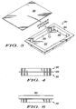
- cooling chamber 212 is shown as being press formed from a sheet 300, such as a sheet of aluminum, aluminum alloy, or other suitable material.
- the sheet 300 may contain a brazing alloy impregnated in the aluminum or may be of a type of material such that a brazing foil is used during a brazing process to seal the two cooling chamber members 210 and 212 together.
- the brazed sheet may be, for example, 0.7 mm thick or any other suitable thickness.
- Each of the cooling chamber members 210 and 212 are formed as unitary members from separate sheets.
- Each of the cooling chamber members 210 and 212 have offset surfaces 302 that are offset from a perimeter surface 304. The offset surfaces of each of the cooling chamber members define the cooling cavity 214.
- Internal sidewalls 306 are considered part of the offset surface that defines the cooling cavity.
- An outer portion of the perimeter surface 204 serves as the brazing surface used to braze the first and second cooling chamber members 210 and 212 together to form a sealed cooling cavity. Accordingly, a braze joint 400 (FIG. 4) is formed when the two cooling chamber members 210 and 212 are brazed together.
- a non-integral support member 500 is interposed between the first cooling chamber member 210 and the second cooling chamber member 212 and is located within the cooling cavity 214.
- the non-integral support member 500 may be any suitable support member or structure that provides structural support between the cooling chamber member 210 and cooling chamber member 212. Accordingly, the non-integral support member may be one or more bosses or other suitable structures.
- the non-integral support member 500 includes liquid pass through channels that allow the cooling liquid to flow in longitudinal and latitudinal directions or in any other suitable directions to allow suitable liquid flow through the support member 500 while still providing structural support.
- a preferred structure of the non-integral support member is a lanced offset fin that is brazed to internal surfaces of the first and second cooling chamber member.
- the lanced offset fin may be any suitable lanced offset fin stock such as the type available for example from Robinson Fin Machines Inc., Kenton, Ohio.
- the non-integral support member 500 is lanced offset fin stock, it may be suitably sized to fit within the cooling cavity.
- the non-integral support member 500 is coupled to contact an internal cavity surface such as the offset surfaces of both the first and second cooling chamber members 210 and 212.
- each cooling chamber member 210 and 212 each form one half of a box like cooling cavity.
- any suitable shape may be used.
- each cooling chamber may be formed as more or less than one half of the cooling cavity.
- multiple cooling cavities may be formed.
- FIG. 6 illustrates a cooling chamber cover 600 is made of a flat sheet as opposed to a pressed unitary member having an offset surface and a perimeter surface.
- the two-phase cooling module is made from a flat cooling chamber cover and a cooling chamber member that is press formed as a unitary member and having an offset surface and a perimeter surface as described above.
- the offset surface defines the cooling cavity and an internal surface of the cooling chamber cover defines a wall of the cooling cavity.
- the cooling chamber cover 600 is brazed to at least a portion of the perimeter surface of the cooling chamber member 212.
- a first sheet such as a sheet of aluminum or aluminum alloy or any other suitable material, is press formed to form a unitary first cavity surface and a perimeter surface, namely, the cooling chamber member.
- another cooling chamber member is formed by press forming a second sheet to form a corresponding unitary second cavity surface and a second perimeter surface.
- the brazing operation is performed once with the non-integral support member being placed inside the cooling cavity and wherein the cooling chamber members are brazed together along perimeter surfaces and the support member is brazed to both of the cavity surfaces internal to the two-phase cooling module.
- brazing foil may not be needed to facilitate the brazing operation.
- a window-shaped brazing foil pattern may be used and can be placed on the perimeter surface of one of the cooling chamber members to allow perimeter surfaces of the cooling chamber members to be brazed to form the brazing joint.
- a fill port is put in a surface of the module to allow the cooling liquid to be placed within the module. This may include, for example, drilling or punching holes within the cooling module as known in the art.
- the above press formed two-phase cooling module can reduce the amount of wasted aluminum as well as speed up the manufacturing process via the press forming operation. Moreover, the afore-described two-phase cooling module avoids the need for stamping laminate sheets with protrusions therein. Other advantages will be recognized by those of ordinary skill in the art.
Abstract
Description
Claims (10)
- A two phase cooling module for electronic components comprising:a first cooling chamber member press formed as a unitary member having a first offset surface and a first perimeter surface; anda second cooling chamber member, operatively sealed with the first cooling chamber, press formed as a unitary member having a second offset surface and a second perimeter surface such that the first and second offset surface define a cooling cavity.
- The module of claim 1 including a non integral support member interposed between the first cooling chamber member and the second cooling chamber member and located within the cooling cavity.
- The module of claim 2 wherein the non-integral support member is a member configured as a lanced offset fin that is brazed to the first and second cooling chamber member.
- The module of claim 2 wherein the non-integral support member is operatively coupled to contact an internal cavity surface associated with the both the first and second offset surfaces.
- The module of claim 1 including a two phase cooling liquid and electronic components operatively coupled to an external surface of the module.
- A two phase cooling module for electronic components comprising:a cooling chamber cover; anda cooling chamber member, operatively sealed with the cooling chamber cover, press formed as a unitary member and having an offset surface and a perimeter surface such that the offset surface defines a cooling cavity.
- The module of claim 6 including a non integral support member interposed between the first cooling chamber cover and the cooling chamber member and located within the cooling cavity.
- The module of claim 7 wherein the non-integral support member is a member configured as a lanced offset fin that is brazed to the cooling chamber cover and to at least a portion of the offset surface of the cooling chamber member.
- The module of claim 6 including a two phase cooling liquid and electronic components operatively coupled to an external surface of the module.
- A method for making a two phase cooling module for electronic components comprising the steps of:press forming a first sheet to form a unitary first cavity surface and a first perimeter surface;press forming a second sheet to form a corresponding unitary second cavity surface and a second perimeter surface; andbrazing a support member to at least one of the first and second cavity surfaces.
Applications Claiming Priority (2)
| Application Number | Priority Date | Filing Date | Title |
|---|---|---|---|
| US812602 | 1991-12-23 | ||
| US09/812,602 US20020134534A1 (en) | 2001-03-20 | 2001-03-20 | Press formed two-phase cooling module and method for making same |
Publications (2)
| Publication Number | Publication Date |
|---|---|
| EP1244145A2 true EP1244145A2 (en) | 2002-09-25 |
| EP1244145A3 EP1244145A3 (en) | 2006-03-22 |
Family
ID=25210084
Family Applications (1)
| Application Number | Title | Priority Date | Filing Date |
|---|---|---|---|
| EP02004852A Withdrawn EP1244145A3 (en) | 2001-03-20 | 2002-03-04 | Press formed two-phase cooling module and method for making same |
Country Status (3)
| Country | Link |
|---|---|
| US (1) | US20020134534A1 (en) |
| EP (1) | EP1244145A3 (en) |
| CN (1) | CN1375868A (en) |
Cited By (1)
| Publication number | Priority date | Publication date | Assignee | Title |
|---|---|---|---|---|
| EP1538884A2 (en) * | 2003-12-02 | 2005-06-08 | Hitachi, Ltd. | Liquid cooling system for use in an electronic apparatus |
Families Citing this family (4)
| Publication number | Priority date | Publication date | Assignee | Title |
|---|---|---|---|---|
| US20080080133A1 (en) * | 2006-10-02 | 2008-04-03 | Hsiu-Wei Yang | Flat type heat pipe device and method of fabrication thereof |
| US20100326629A1 (en) * | 2009-06-26 | 2010-12-30 | Meyer Iv George Anthony | Vapor chamber with separator |
| US10458716B2 (en) * | 2014-11-04 | 2019-10-29 | Roccor, Llc | Conformal thermal ground planes |
| US10999952B1 (en) * | 2020-01-02 | 2021-05-04 | Taiwan Microloops Corp. | Vapor chamber and manufacturing method thereof |
Citations (2)
| Publication number | Priority date | Publication date | Assignee | Title |
|---|---|---|---|---|
| US5924482A (en) | 1997-10-29 | 1999-07-20 | Motorola, Inc. | Multi-mode, two-phase cooling module |
| US5937937A (en) | 1998-06-18 | 1999-08-17 | Motorola, Inc. | Heat sink and method for removing heat from a plurality of components |
Family Cites Families (4)
| Publication number | Priority date | Publication date | Assignee | Title |
|---|---|---|---|---|
| FR1422168A (en) * | 1964-10-21 | 1965-12-24 | Labo Cent Telecommunicat | Semiconductor device enhancements |
| US4944344A (en) * | 1988-10-31 | 1990-07-31 | Sundstrand Corporation | Hermetically sealed modular electronic cold plate utilizing reflux cooling |
| JP3164518B2 (en) * | 1995-12-21 | 2001-05-08 | 古河電気工業株式会社 | Flat heat pipe |
| GB2342153B (en) * | 1998-04-13 | 2002-01-09 | Furukawa Electric Co Ltd | Plate type heat pipe and cooling device using same |
-
2001
- 2001-03-20 US US09/812,602 patent/US20020134534A1/en not_active Abandoned
-
2002
- 2002-03-04 EP EP02004852A patent/EP1244145A3/en not_active Withdrawn
- 2002-03-20 CN CN02104486A patent/CN1375868A/en active Pending
Patent Citations (2)
| Publication number | Priority date | Publication date | Assignee | Title |
|---|---|---|---|---|
| US5924482A (en) | 1997-10-29 | 1999-07-20 | Motorola, Inc. | Multi-mode, two-phase cooling module |
| US5937937A (en) | 1998-06-18 | 1999-08-17 | Motorola, Inc. | Heat sink and method for removing heat from a plurality of components |
Cited By (3)
| Publication number | Priority date | Publication date | Assignee | Title |
|---|---|---|---|---|
| EP1538884A2 (en) * | 2003-12-02 | 2005-06-08 | Hitachi, Ltd. | Liquid cooling system for use in an electronic apparatus |
| EP1538884A3 (en) * | 2003-12-02 | 2005-10-12 | Hitachi, Ltd. | Liquid cooling system for use in an electronic apparatus |
| US7044198B2 (en) | 2003-12-02 | 2006-05-16 | Hitachi, Ltd. | Electronic apparatus |
Also Published As
| Publication number | Publication date |
|---|---|
| EP1244145A3 (en) | 2006-03-22 |
| US20020134534A1 (en) | 2002-09-26 |
| CN1375868A (en) | 2002-10-23 |
Similar Documents
| Publication | Publication Date | Title |
|---|---|---|
| US20020135979A1 (en) | Two-phase cooling module and method of making the same | |
| KR100260676B1 (en) | Cooling apparatus boling and condensing refrigerant | |
| US4941530A (en) | Enhanced air fin cooling arrangement for a hermetically sealed modular electronic cold plate utilizing reflux cooling | |
| US4944344A (en) | Hermetically sealed modular electronic cold plate utilizing reflux cooling | |
| US6749013B2 (en) | Heat sink | |
| US20030159806A1 (en) | Flat-plate heat-pipe with lanced-offset fin wick | |
| EP1477762A2 (en) | Thermosyphon and method for producing it | |
| US6073683A (en) | Cooling apparatus using boiling and condensing refrigerant and method for manufacturing the same | |
| JPH0363825B2 (en) | ||
| EP3589904B1 (en) | High-performance electronics cooling system | |
| JP3608272B2 (en) | Boiling cooling device and manufacturing method thereof | |
| EP1244145A2 (en) | Press formed two-phase cooling module and method for making same | |
| US6234242B1 (en) | Two-phase thermosyphon including a porous structural material having slots disposed therein | |
| JPH08204075A (en) | Plate-fin type element cooler | |
| US20070277962A1 (en) | Two-phase cooling system for cooling power electronic components | |
| US20220295674A1 (en) | Air heat exchanger and method for production thereof and electronic assembly equipped therewith | |
| CN112254558B (en) | Three-dimensional laminated heat pipe and preparation method thereof | |
| EP1863085A2 (en) | Two-phase cooling system for cooling power electronic components | |
| JPH05304384A (en) | Heat pipe type heat sink | |
| CN114390869A (en) | One-way heat transfer heat pipe with Y-shaped diversion table liquid absorption core and processing method thereof | |
| JP2001024374A (en) | Heat sink for electrical heating element generating heat in high density | |
| JPH10288481A (en) | Planar heat pipe and cooling structure employing it | |
| JPH05304383A (en) | Heat sink for high output electronic apparatus | |
| WO1999042781A1 (en) | Heat exchanger and method for producing the heat exchanger | |
| JPH0923081A (en) | Boiling cooling equipment |
Legal Events
| Date | Code | Title | Description |
|---|---|---|---|
| PUAI | Public reference made under article 153(3) epc to a published international application that has entered the european phase |
Free format text: ORIGINAL CODE: 0009012 |
|
| AK | Designated contracting states |
Kind code of ref document: A2 Designated state(s): AT BE CH CY DE DK ES FI FR GB GR IE IT LI LU MC NL PT SE TR |
|
| AX | Request for extension of the european patent |
Free format text: AL;LT;LV;MK;RO;SI |
|
| PUAL | Search report despatched |
Free format text: ORIGINAL CODE: 0009013 |
|
| AK | Designated contracting states |
Kind code of ref document: A3 Designated state(s): AT BE CH CY DE DK ES FI FR GB GR IE IT LI LU MC NL PT SE TR |
|
| AX | Request for extension of the european patent |
Extension state: AL LT LV MK RO SI |
|
| 17P | Request for examination filed |
Effective date: 20060922 |
|
| AKX | Designation fees paid |
Designated state(s): DE GB |
|
| 17Q | First examination report despatched |
Effective date: 20080423 |
|
| R17C | First examination report despatched (corrected) |
Effective date: 20080623 |
|
| STAA | Information on the status of an ep patent application or granted ep patent |
Free format text: STATUS: THE APPLICATION HAS BEEN WITHDRAWN |
|
| R17C | First examination report despatched (corrected) |
Effective date: 20080803 |
|
| 18W | Application withdrawn |
Effective date: 20080919 |
|
| P01 | Opt-out of the competence of the unified patent court (upc) registered |
Effective date: 20230524 |