EP1538715A2 - Telekommunikationsverbinder mit verbesserter Leistung - Google Patents
Telekommunikationsverbinder mit verbesserter Leistung Download PDFInfo
- Publication number
- EP1538715A2 EP1538715A2 EP05001920A EP05001920A EP1538715A2 EP 1538715 A2 EP1538715 A2 EP 1538715A2 EP 05001920 A EP05001920 A EP 05001920A EP 05001920 A EP05001920 A EP 05001920A EP 1538715 A2 EP1538715 A2 EP 1538715A2
- Authority
- EP
- European Patent Office
- Prior art keywords
- shield
- outlet
- plug
- contact
- core
- Prior art date
- Legal status (The legal status is an assumption and is not a legal conclusion. Google has not performed a legal analysis and makes no representation as to the accuracy of the status listed.)
- Granted
Links
Images


Classifications
-
- H—ELECTRICITY
- H01—ELECTRIC ELEMENTS
- H01R—ELECTRICALLY-CONDUCTIVE CONNECTIONS; STRUCTURAL ASSOCIATIONS OF A PLURALITY OF MUTUALLY-INSULATED ELECTRICAL CONNECTING ELEMENTS; COUPLING DEVICES; CURRENT COLLECTORS
- H01R13/00—Details of coupling devices of the kinds covered by groups H01R12/70 or H01R24/00 - H01R33/00
- H01R13/46—Bases; Cases
- H01R13/465—Identification means, e.g. labels, tags, markings
-
- H—ELECTRICITY
- H01—ELECTRIC ELEMENTS
- H01R—ELECTRICALLY-CONDUCTIVE CONNECTIONS; STRUCTURAL ASSOCIATIONS OF A PLURALITY OF MUTUALLY-INSULATED ELECTRICAL CONNECTING ELEMENTS; COUPLING DEVICES; CURRENT COLLECTORS
- H01R13/00—Details of coupling devices of the kinds covered by groups H01R12/70 or H01R24/00 - H01R33/00
- H01R13/46—Bases; Cases
- H01R13/502—Bases; Cases composed of different pieces
- H01R13/506—Bases; Cases composed of different pieces assembled by snap action of the parts
-
- H—ELECTRICITY
- H01—ELECTRIC ELEMENTS
- H01R—ELECTRICALLY-CONDUCTIVE CONNECTIONS; STRUCTURAL ASSOCIATIONS OF A PLURALITY OF MUTUALLY-INSULATED ELECTRICAL CONNECTING ELEMENTS; COUPLING DEVICES; CURRENT COLLECTORS
- H01R13/00—Details of coupling devices of the kinds covered by groups H01R12/70 or H01R24/00 - H01R33/00
- H01R13/62—Means for facilitating engagement or disengagement of coupling parts or for holding them in engagement
- H01R13/627—Snap or like fastening
- H01R13/6275—Latching arms not integral with the housing
-
- H—ELECTRICITY
- H01—ELECTRIC ELEMENTS
- H01R—ELECTRICALLY-CONDUCTIVE CONNECTIONS; STRUCTURAL ASSOCIATIONS OF A PLURALITY OF MUTUALLY-INSULATED ELECTRICAL CONNECTING ELEMENTS; COUPLING DEVICES; CURRENT COLLECTORS
- H01R13/00—Details of coupling devices of the kinds covered by groups H01R12/70 or H01R24/00 - H01R33/00
- H01R13/646—Details of coupling devices of the kinds covered by groups H01R12/70 or H01R24/00 - H01R33/00 specially adapted for high-frequency, e.g. structures providing an impedance match or phase match
- H01R13/6461—Means for preventing cross-talk
- H01R13/6471—Means for preventing cross-talk by special arrangement of ground and signal conductors, e.g. GSGS [Ground-Signal-Ground-Signal]
-
- H—ELECTRICITY
- H01—ELECTRIC ELEMENTS
- H01R—ELECTRICALLY-CONDUCTIVE CONNECTIONS; STRUCTURAL ASSOCIATIONS OF A PLURALITY OF MUTUALLY-INSULATED ELECTRICAL CONNECTING ELEMENTS; COUPLING DEVICES; CURRENT COLLECTORS
- H01R13/00—Details of coupling devices of the kinds covered by groups H01R12/70 or H01R24/00 - H01R33/00
- H01R13/648—Protective earth or shield arrangements on coupling devices, e.g. anti-static shielding
- H01R13/658—High frequency shielding arrangements, e.g. against EMI [Electro-Magnetic Interference] or EMP [Electro-Magnetic Pulse]
- H01R13/6581—Shield structure
- H01R13/6585—Shielding material individually surrounding or interposed between mutually spaced contacts
-
- H—ELECTRICITY
- H01—ELECTRIC ELEMENTS
- H01R—ELECTRICALLY-CONDUCTIVE CONNECTIONS; STRUCTURAL ASSOCIATIONS OF A PLURALITY OF MUTUALLY-INSULATED ELECTRICAL CONNECTING ELEMENTS; COUPLING DEVICES; CURRENT COLLECTORS
- H01R13/00—Details of coupling devices of the kinds covered by groups H01R12/70 or H01R24/00 - H01R33/00
- H01R13/648—Protective earth or shield arrangements on coupling devices, e.g. anti-static shielding
- H01R13/658—High frequency shielding arrangements, e.g. against EMI [Electro-Magnetic Interference] or EMP [Electro-Magnetic Pulse]
- H01R13/6591—Specific features or arrangements of connection of shield to conductive members
- H01R13/65912—Specific features or arrangements of connection of shield to conductive members for shielded multiconductor cable
- H01R13/65915—Twisted pair of conductors surrounded by shield
-
- H—ELECTRICITY
- H01—ELECTRIC ELEMENTS
- H01R—ELECTRICALLY-CONDUCTIVE CONNECTIONS; STRUCTURAL ASSOCIATIONS OF A PLURALITY OF MUTUALLY-INSULATED ELECTRICAL CONNECTING ELEMENTS; COUPLING DEVICES; CURRENT COLLECTORS
- H01R13/00—Details of coupling devices of the kinds covered by groups H01R12/70 or H01R24/00 - H01R33/00
- H01R13/648—Protective earth or shield arrangements on coupling devices, e.g. anti-static shielding
- H01R13/658—High frequency shielding arrangements, e.g. against EMI [Electro-Magnetic Interference] or EMP [Electro-Magnetic Pulse]
- H01R13/6591—Specific features or arrangements of connection of shield to conductive members
- H01R13/6592—Specific features or arrangements of connection of shield to conductive members the conductive member being a shielded cable
-
- H—ELECTRICITY
- H01—ELECTRIC ELEMENTS
- H01R—ELECTRICALLY-CONDUCTIVE CONNECTIONS; STRUCTURAL ASSOCIATIONS OF A PLURALITY OF MUTUALLY-INSULATED ELECTRICAL CONNECTING ELEMENTS; COUPLING DEVICES; CURRENT COLLECTORS
- H01R24/00—Two-part coupling devices, or either of their cooperating parts, characterised by their overall structure
- H01R24/60—Contacts spaced along planar side wall transverse to longitudinal axis of engagement
-
- H—ELECTRICITY
- H01—ELECTRIC ELEMENTS
- H01R—ELECTRICALLY-CONDUCTIVE CONNECTIONS; STRUCTURAL ASSOCIATIONS OF A PLURALITY OF MUTUALLY-INSULATED ELECTRICAL CONNECTING ELEMENTS; COUPLING DEVICES; CURRENT COLLECTORS
- H01R4/00—Electrically-conductive connections between two or more conductive members in direct contact, i.e. touching one another; Means for effecting or maintaining such contact; Electrically-conductive connections having two or more spaced connecting locations for conductors and using contact members penetrating insulation
- H01R4/24—Connections using contact members penetrating or cutting insulation or cable strands
- H01R4/2416—Connections using contact members penetrating or cutting insulation or cable strands the contact members having insulation-cutting edges, e.g. of tuning fork type
- H01R4/242—Connections using contact members penetrating or cutting insulation or cable strands the contact members having insulation-cutting edges, e.g. of tuning fork type the contact members being plates having a single slot
- H01R4/2425—Flat plates, e.g. multi-layered flat plates
- H01R4/2429—Flat plates, e.g. multi-layered flat plates mounted in an insulating base
-
- H—ELECTRICITY
- H01—ELECTRIC ELEMENTS
- H01R—ELECTRICALLY-CONDUCTIVE CONNECTIONS; STRUCTURAL ASSOCIATIONS OF A PLURALITY OF MUTUALLY-INSULATED ELECTRICAL CONNECTING ELEMENTS; COUPLING DEVICES; CURRENT COLLECTORS
- H01R13/00—Details of coupling devices of the kinds covered by groups H01R12/70 or H01R24/00 - H01R33/00
- H01R13/648—Protective earth or shield arrangements on coupling devices, e.g. anti-static shielding
- H01R13/658—High frequency shielding arrangements, e.g. against EMI [Electro-Magnetic Interference] or EMP [Electro-Magnetic Pulse]
- H01R13/6591—Specific features or arrangements of connection of shield to conductive members
- H01R13/6594—Specific features or arrangements of connection of shield to conductive members the shield being mounted on a PCB and connected to conductive members
-
- H—ELECTRICITY
- H01—ELECTRIC ELEMENTS
- H01R—ELECTRICALLY-CONDUCTIVE CONNECTIONS; STRUCTURAL ASSOCIATIONS OF A PLURALITY OF MUTUALLY-INSULATED ELECTRICAL CONNECTING ELEMENTS; COUPLING DEVICES; CURRENT COLLECTORS
- H01R2107/00—Four or more poles
-
- H—ELECTRICITY
- H01—ELECTRIC ELEMENTS
- H01R—ELECTRICALLY-CONDUCTIVE CONNECTIONS; STRUCTURAL ASSOCIATIONS OF A PLURALITY OF MUTUALLY-INSULATED ELECTRICAL CONNECTING ELEMENTS; COUPLING DEVICES; CURRENT COLLECTORS
- H01R2201/00—Connectors or connections adapted for particular applications
- H01R2201/16—Connectors or connections adapted for particular applications for telephony
-
- H—ELECTRICITY
- H01—ELECTRIC ELEMENTS
- H01R—ELECTRICALLY-CONDUCTIVE CONNECTIONS; STRUCTURAL ASSOCIATIONS OF A PLURALITY OF MUTUALLY-INSULATED ELECTRICAL CONNECTING ELEMENTS; COUPLING DEVICES; CURRENT COLLECTORS
- H01R9/00—Structural associations of a plurality of mutually-insulated electrical connecting elements, e.g. terminal strips or terminal blocks; Terminals or binding posts mounted upon a base or in a case; Bases therefor
- H01R9/03—Connectors arranged to contact a plurality of the conductors of a multiconductor cable, e.g. tapping connections
- H01R9/05—Connectors arranged to contact a plurality of the conductors of a multiconductor cable, e.g. tapping connections for coaxial cables
- H01R9/053—Connectors arranged to contact a plurality of the conductors of a multiconductor cable, e.g. tapping connections for coaxial cables using contact members penetrating insulation
Definitions
- the invention relates generally to telecommunications connectors and in particular to a telecommunications plug and outlet having enhanced performance characteristics.
- Transmission requirements for Category 4 components are specified up to 20 MHZ.
- Transmission requirements for Category 5 components are specified up to 100 MHZ.
- New standards are being developed continuously and currently it is expected that future standards will require transmission requirements of at least 600 MHZ. To achieve such transmission rates, fully shielded twisted pair cable will be necessary in which each pair is individually wrapped in a foil or screen. In addition, all pairs are wrapped together in a layer of foil or screen.
- Nelecommunications connectors are organized in sets of pairs, typically made up of a tip and ring connector. As telecommunications connectors are reduced in size, adjacent pairs are placed closer to each other creating crosstalk between adjacent pairs. To comply with the near-end crosstalk requirements, a variety of techniques are used in the art.
- U.S. Pat. No. 5,593,311 discloses a shielded compact data connector designed to reduce crosstalk between contacts of the connector. Pairs of contacts are placed within metallic channels. When the connectors are mated, the channels abut against each other to enclose each pair in a metallic shield.
- One disadvantage to the design in U.S. Pat. No. 5,593,311 is that the metallic channels are joined at a butt joint; one surface abuts against the adjacent surface with no overlap. Since all components include some manufacturing tolerance, there is a potential for gaps between the shields thereby reducing the shielding effect.
- Another disadvantage is that wires having the foil removed can be exposed to each other at the rear of the connector thus leading to crosstalk. Thus, there is a perceived need in the art for a connector having improved pair shielding.
- the enhanced performance telecommunications connector of the present invention comprising a conductive core having core side walls and a horizontal shield joined to and perpendicular to said side walls, at least one contact carrier containing a contact, said contact having an insulation displacement contact for making electrical connection with a wire, said contact carrier being positioned on said horizontal shield between said side walls, characterized in that:
- FIG. 1 is a perspective view of an assembled plug, shown generally as 100, in accordance with the present invention.
- the plug 100 includes a top cover 102, a bottom cover 104 and a core 106.
- the top cover 102, bottom cover 104 and core 106 are all conductive to provide shielding as described herein. These conductive components may be made from metal, metallized plastic or any other known conductive material.
- Core 106 supports insulative (e.g. plastic) contact carriers 108. Each contact carrier 108 includes two contacts 160 defining a pair.
- a boot 112 provides strain relief and is made from a pliable plastic or rubber.
- Also shown in FIG. 1 is cable 10 entering boot 112.
- a latch 114 is provided on the top cover 102 for coupling the plug 100 to outlet 300 as described herein.
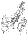
- FIG. 2 is an exploded, perspective view of the plug 100.
- Latch 114 is made up of a latch body 116 secured to the top cover at fulcrum 118.
- a lip 120 is provided on the bottom of the latch body 116 for engaging a groove formed in outlet 300. This secures the plug 100 to the outlet 300.
- An important feature of latch 114 is a latch extension 122 that couples the latch body 116 to the top cover 102.
- the latch extension 122 is a pliable, arcuate member that flexes when pressure is applied to latch body 116. Telecommunications plugs are often pulled through wall spaces during installation. The latch extension 122 reduces the likelihood that the plug 100 will be caught on other cables, wall comers, studs, etc.
- Top cover 102 includes a semi-circular groove 129 and bottom cover 104 includes a similar semicircular groove 129 that receive a circular lip 113 (FIG. 7) in boot 112 as described below.
- Two top cover latches 128 engage two bottom cover recesses 130 to secure top cover 102 to bottom cover 104.
- Plug core 106 includes a first planar shield 132 and a second planar shield 134 substantially perpendicular to the first planar shield 132.
- Plug core 106 also includes side walls 136.
- the top and bottom of each side wall 136 include a ridge 140.
- Ridges 140 extend beyond side wall 136 and overlap an edge 142 of the top cover 102 and bottom cover 104.
- Ridges 140 are shown as having a generally triangular cross section, but it is understood that different geometries may be used without departing from the scope of the invention. Ridges 140 serve to locate the core 106 within the top and bottom covers and overlap the edges of the top cover and bottom cover to provide better shielding than a butt joint.
- the second planar shield 134 also includes a ridge 144 on the top and bottom surfaces.
- central ridge 144 is triangular, however, it is understood that other geometries may be used without departing from the invention.
- Central ridge 144 engages channels 178 formed in top cover 102 and bottom cover 104 as described below with reference to FIGS. 3 and 4.
- Two ribs 146 are formed on the inside surface of each side wall 136 and are parallel to and spaced apart from first planar shield 132. Similar ribs are formed on each surface of the second planar shield 134.
- Contact carrier 108 has a planar base 148 which rests on the first planar shield 132.
- Base 148 includes two flanges 150 extending away from the base and a stop 152 adjacent to the flanges 150.
- each side wall 136 and each side of second planar shield 134 also include a first ledge 149 and a second ledge 147 which are used to secure a termination cap to the plug core 106 as described below with reference to FIGS. 6-10.
- FIG. 3 is an exploded, perspective view of the top cover 102.
- the top cover includes a shield contact 164 which electrically connects the ground layer of cable 10 to the plug core 106.
- Shield contact 164 is conductive and is preferably made from metal.
- Shield contact 164 has an arcuate portion 166 formed to generally follow the shape of cable 10.
- Arcuate portion 166 includes barbs 168 that pierce the ground layer of cable 10 and the cable jacket. This electrically and mechanically connects the shield contact 164 to cable 10.
- Shield contact 164 includes a pad 170 having two openings 172 formed therein for receiving two posts 176 formed in top cover 102. The friction fit between posts 176 and openings 172 secures the shield contact 164 to top cover 102.
- a tab 174 extends away from pad 170 and contacts the plug core 106.
- a channel 178 is formed in the top cover 102 for receiving central ridge 144 on plug core 106. This allows the central ridge 144 to be overlapped by the side walls of the channel 178 and provides better shielding than a conventional butt joint.
- a notch 162 is provided in the front face 103 of top cover 102 to receive the second planar shield 134.
- the front face 103 of plug 102 also includes three recessed areas 163 that receive extensions on the front face 317 of outlet 300 as described below.
- Top cover 102 includes side wall recesses 139 for receiving rear extensions 137 on plug core 106 (FIG. 6) to create an overlap between the rear of plug core side wall 328 and the plug top cover.
- Top cover 102 also includes side walls 105 having a top side wall extensions 143 that engage outlet side wall recesses 343 (FIG. 4) to create overlap between the side walls 105 of the top plug cover 102 and the side walls
- FIG. 4 is an exploded, perspective view of the bottom cover 104.
- Bottom cover 104 is similar to top cover 102 in that both use shield contact 164 in the same manner.
- Bottom cover 104 also includes channel 178 for receiving central ridge 144 on second planar shield 134. As noted above, this allows the central ridge 144 to be overlapped by the sides of the channel 178 and provides better shielding than a conventional butt joint.
- Notch 162 is provided in the front face 103 of bottom cover 104 to receive second planar shield 134.
- Bottom cover 104 includes side walls 107 having side wall recess 139, similar to those on top cover 102, for receiving rear extensions 137 on side wall 136.
- bottom cover 104 includes second side wall recesses 343 for receiving side wall extensions 143 on top cover 102.
- the front face 103 of bottom cover 104 is similar to that of top cover 102 and includes recesses 163 for receiving extensions on the front face 317 of the outlet 300.
- the front face 103 of bottom cover 104 also includes a lip 165, interrupted by recess 163, that overlaps the outside surface of the bottom wall 332 of outlet core 306.
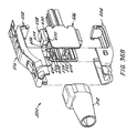
- FIG. 5 is an exploded perspective view of a contact carrier 108.
- the contact carrier includes two channels 186, each of which receives a contact 160.
- Each contact 160 has a generally planar body 180, a contact end 182 and a termination end 183.
- the termination end includes an insulation displacement contact 184 that pierces the insulation of individual wires in cable 10 to make an electrical contact with the wire as is known in the art. Installation of the wires in the insulation displacement contact 184 is described herein with reference to FIGS. 8-10.
- Each insulation displacement contact is angled relative to the longitudinal axis of body 180 at an angle of 45 degrees.
- the plug 100 includes four contact carriers 108, each having a pair of contacts 160 for a total of eight contacts.
- FIG. 6 is an exploded, perspective view of the plug 100 including termination caps 186.
- a termination cap 186 is provided for each pair of contacts 160.
- a termination cap forces wires onto an insulation displacement contact to pierce the insulation and electrically connect the wire and the insulation displacement contact.
- Termination cap 186 includes a first lip 188 and a second lip 190 that straddle ledges 149 and 147 on the plug core 106.
- the first lip 188 and the second lip 190 have a beveled surface and first ledge 149 and second ledge 147 similarly include a beveled surface to facilitate installation of the termination cap 186 as disclosed below.
- Each termination cap 186 also includes two contact openings 192 for receiving the insulation displacement contacts 184 and a pair of wire openings 194 for receiving wires from cable 10.
- the wire openings 194 are aligned with the insulation displacement contacts 184 in plug core 106.
- the plug in FIG. 6 is shown in the state as received by the customer.
- Termination caps 186 are positioned in the plug core 106 and retained in a first positioned.
- First lip 188 rests upon first ledge 149 to hold the termination cap 186 in a first position and second lip 190 is positioned beneath first ledge 149 to prevent the termination cap 186 from being inadvertently removed from the plug core 106.
- FIG. 7 is another exploded, perspective view of the plug 100. As shown in FIG. 7, each termination cap 186 is in the first position by virtue of first lip 188 and second lip 190 straddling first ledge 149.
- Boot 112 includes a cylindrical lip 113 that engages groove 129 formed in the top cover 102 and the bottom cover 104. Slots 115 may be formed through the boot 122 and perpendicular to lip 113 to allow the lip 113 to expand during installation of the boot 112 and reduce the force needed to install and remove boot 112.
- cable 10 includes eight wires 198. Each pair of wires 198 is encased by a wire pair shield 200. Ground layer 196 is also housed within cable 10 and is pulled back over the outside jacket of cable 10. Wires 198 are inserted into wire openings 194 in termination caps 186. As described above, each wire opening 194 is aligned with an insulation displacement contact 184 and thus each wire 198 is positioned above an insulation displacement contact 184. It is understood that boot 112 is placed over cable 10 prior to inserting wires 198 into termination caps 186. FIG. 9 shows the wires 198 positioned in the wire openings 194.
- each termination cap 186 is positioned in the termination caps 186, force is applied to each termination cap 186 towards the plug core 106 in the direction shown by the arrows in FIG. 9.
- a single hand tool can be used to apply force to all four termination caps 186 at the same time to provide for easy installation.
- FIG. 10 shows the termination caps 186 in a second position.
- First lip 188 and second lip 190 now straddle second ledge 147 to hold the termination cap 186 in the second position.
- the wires 198 positioned in wire openings 194 are driven onto insulation displacement contacts 184.
- the insulation displacement contacts 184 split the insulation on each wire 198 thereby making electrical contact between the wires 198 and the contacts 160.
- An important aspect of the invention shown in FIG. 10 is the use of a buffer zone 206.
- the length of the first planar shield 132 and second planar shield 134 is such that a portion of the first planar shield 132 and the second planar shield extend beyond the rear of each termination cap 186 to establish a buffer zone 206.
- the buffer zone 206 is important because during installation, the wire pair shield 200 is removed so that individual wires can be inserted in wire openings 194. Even assuming that the installer removed the exact recommended length of wire pair shield 200, a small amount of exposed wire will create cross talk between adjacent pairs at frequencies of greater than 600 MHZ. In non-ideal installations, the installer will remove too much of the wire pair shield 200. Thus, the buffer zone 206 reduces cross talk in ideal or non-ideal installations and enhances the connector performance.
- the buffer zone should have a length, measured from the rear of the termination cap 186, greater than the length of exposed wire 198 (wire pair shield removed) in a worst case installation.
- top cover 102 and bottom cover 104 each include projections 202 that engage similarly shaped recesses 204 on plug core 106 to secure the top cover 102 and bottom cover 104 to plug core 106.
- top cover latches 128 engage bottom cover openings 130 to secure the top cover 102 to the bottom cover 104.
- Barbs 168 on shield contacts 164 penetrate the ground layer 196 and the cable jacket to mechanically and electrically connect the shield connectors 164 to cable 10.
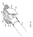
- the final step in the plug assembly is securing the boot 112 to the plug. As shown in FIG. 12, the boot 112 is snapped onto the top and bottom covers. Lip 113 on the inside surface of boot 112 engages the groove 129 formed in top cover 102 and bottom cover 104.
- FIG. 12A is a perspective view of the plug in an alternative embodiment.
- boot 112 includes two L-shaped channels 197 which receive post 124 formed on the top cover 102 and post 126 formed on the bottom cover 104 (FIG. 12B).
- Boot 112 is secured to the top cover 102 and bottom cover 104 by placing posts 124 and 126 in channels 197 and rotating the boot 112.
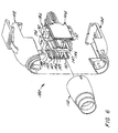
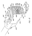
- FIG. 13 is a perspective view of an outlet 300 for use with plug 100.
- the outlet 300 includes a top cover 302, a bottom cover 304 and a core 306.
- the top cover 302, bottom cover 304 and core 306 are all conductive to provide shielding as described herein. These conductive components may be made from metal, metallized plastic or any other known conductive material.
- Core 306 supports insulative contact carriers 308. Each contact carrier includes contacts 310.
- An optional door 311 is also provided to prevent contamination (e.g. dust) from entering outlet 300.
- Top cover 302 includes a pair of resilient arms 312 having notches 314 formed therein. Notches 314 receive the edge of a faceplate as will be described below with reference to FIG. 23. Another notch 315 is formed on the bottom of outlet core 306 for receiving another edge of the faceplate. Notches 314 and 315 lie in a plane that is at an oblique angle relative to the front face 317 of outlet 300. When mounted in a faceplate, this directs the outlet towards the ground and provides for a gravity feed design. The gravity feed reduces the bend angle of the cable connected to plug 100 and reduces the likelihood that the cable will be bent beyond the minimum bend radius and cause signal degradation or loss. Alternatively, notches 314 and 315 may lie in a plane parallel to the front face 317 of outlet 300.
- a member 316 connects the ends of resilient arms 314 and includes a recess 318 on a front face thereof. Recess 318 receives one edge of an identification icon 324 (shown in FIG. 14). The identification icon 324 rests on support surface 320 and engages a recess 322. Both support surface 320 and recess 322 are formed on the outlet core 306.
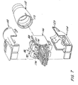
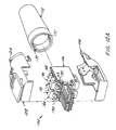
- FIG. 14 is an exploded, perspective view of outlet 300.
- Top cover 302 includes top cover latches 128 that engage bottom cover openings 130 as described above.
- Outlet core 306 is generally rectangular and includes side walls 328, top wall 330 and bottom wall 332.
- a first planar shield 334 extends from the rear of the outlet core and terminates within the interior of the outlet core 306 as will be described below.
- Second planar shield 336 extends the entire length of the outlet core 306 but includes an open region for receiving plug 100 and overlapping the second planar shield 134 in plug 100.
- Side walls 328 include grooves 338 for receiving first planar shield 132 of plug 100.
- Side walls 328 and second planar shield 336 include ribs 340 for securing contact carriers 308 to outlet core 306.
- Second planar shield 336 includes shield extensions 342 having a reduced thickness and extending away from and parallel to second planar shield 336. As will be described below in detail, shield extensions 342 overlap the edges of second planar shield 134 when the plug 100 is mated with outlet 300. Second planar shield 336 also includes a ridge 337 on its top and bottom for engaging channels 178 formed in the outlet top cover 302 and the outlet bottom cover 304. In addition, side walls 328 and second planar shield 336 extend beyond the front face 317 of outlet 300 and engage recesses 163 formed in the front face 103 of the outlet 100. Top wall 330 extends beyond the front face 317 of outlet 300 and overlaps the front face 103 of plug top cover 102. Lip 165 on plug bottom cover 104 overlaps bottom wall 332.
- Door 311 includes two arms having inwardly facing pins 364 that are received in holes 366 on outlet core 306.
- a pair of slots 368 are formed on the inside surface of door 311 for receiving the first planar shield 336 in outlet core 306.
- An identification icon 370 can be mounted to the front of door 311 as described in co-pending U.S. patent application Ser. No. 08/652,230, the contents of which are incorporated herein by reference.
- FIG. 15 is a cross-sectional view of outlet core 306 along line 15--15 of FIG. 14.
- the first planar shield 336 and second planar shield 338 include shield extensions 342' that overlap the ends 133 and 135 of the first planar shield 132 and second planar shield 134 in plug 100.
- Shield extensions 342' have a thickness that is less than the thickness of the first planar shield 336 or the second planar shield 338.
- Hooks 344 on the top and bottom of outlet core 306 engage openings 346 in the top cover 302 and the bottom cover 304.
- FIG. 16 is an exploded, perspective view of top cover 302.
- Top cover 302 includes the shield contact 164 described above with reference to plug 100.
- Top cover 302 additionally includes projections 348 to support the shield contact 164 due to the different geometry of the outlet 300.
- Top cover 302 includes recesses 303 along a top wall 301 and a side wall 307 for receiving extensions 327 on the outlet core 306 (FIG. 19).
- Side walls 307 include projections 309 that are received in recesses 313 on bottom cover 304.
- a channel 178 is provided on top wall 301 for receiving ridge 337 on second planar shield 336.
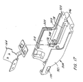
- FIG. 17 is an exploded perspective view of bottom cover 304.
- Bottom cover 304 includes the shield contact 164 described above with reference to plug 100.
- Bottom cover 304 additionally includes projections 348 to support the shield contact 164 due to the different geometry of the outlet 300.
- Recesses 303 are formed on the bottom cover bottom wall 323 and side wall 321 and receive extensions 327 (FIG. 19) on the side walls 328 of outlet core 306.
- Side walls 321 further include recesses 313 for receiving projections 309 on top cover 302.
- a channel 178 is provided on bottom wall 323 for receiving ridge 337 on second planar shield 336.
- FIG. 18 is an exploded, perspective view of contact carrier 308.
- the contact carrier is insulative and includes a generally rectangular housing 352 having a pair of slots 354 formed therein for receiving contacts 350.
- the slots 354 are formed through one surface of housing 352 so that a portion of the contact 350 extends beyond the surface of the housing 352 as shown in FIG. 14.
- the contact 350 includes an insulation displacement contact 356 at one end for piercing the insulation of a wire and making electrical contact. Insulation displacement contact 356 is angled relative to the longitudinal axis of the contact 350 at an angle of 45 degrees.
- Contact 350 also includes a spring portion 358 that extends beyond the surface of the housing 352 as shown in FIG. 14.
- housing 352 includes shoulder 360 that contacts rib 340 on outlet core 306 to secure the contact carrier 308 to the outlet core 306.
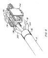
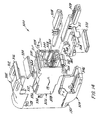
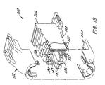
- FIG. 19 is an exploded, perspective view of the outlet 300.
- Termination caps 186 are used to install wires onto the insulation displacement contacts 356.
- Termination caps 186 are identical to those described above with reference to the plug 100.
- Outlet 300 includes first ledges 149 and a second ledges 147 formed on the side walls 328 and second planar shield 336. As described above with reference to plug 100, the termination cap 186 is held in a first position by first lip 188 and second lip 190 straddling first ledge 149.
- Wire openings 194 receive wires 198 and are aligned with insulation displacement contacts 356.
- side walls 328 include extensions 327 on the top, bottom and rear side thereof for engaging recesses 303 on outlet top cover 302 and outlet bottom cover 304.
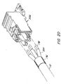
- cable 10 includes eight wires 198. Each pair of wires 198 is encased by a wire pair shield 200. Ground layer 196 is also housed within cable 10 and is pulled back over the outside jacket of cable 10. Wires 198 are inserted into wire openings 194 in termination caps 186. As described above, each wire opening 194 is aligned with an insulation displacement contact 356 and thus each wire 198 is positioned above an insulation displacement contact 356.
- FIG. 21 shows the wires 198 positioned in the wire openings 194. Once the wires 198 are positioned in the termination caps 186, force is applied to each termination cap 186 towards the outlet core 306 in the direction shown by the arrows in FIG. 21. As discussed above with reference to plug 100, a single tool can apply force to all four termination caps at once.
- FIG. 21 shows the termination caps 186 in a second position. First lip 188 and second lip 190 now straddle second ledge 147 to hold the termination cap 186 in the second position. In this state, the wires 198 positioned in wire openings 194 are driven onto insulation displacement contacts 356.
- the outlet 300 also includes a buffer zone 206 similar to that described above with reference to plug 100.
- a portion of first planar shield 336 and the second planar shield 338 extend past the termination caps 186 to provide the buffer zone 206 having the advantages described above with reference to plug 100.
- top cover 302 and bottom cover 304 are placed on outlet core 306 as shown in FIG. 22.
- the opening 346 in both the top cover 302 and the bottom cover 304 is placed over a respective hook 344.
- the top cover 302 and the bottom cover 304 are then rotated towards each other and top cover latches 128 engage bottom cover openings 130 to secure the top cover 302 to the bottom cover 304.
- Barbs 168 on shield contacts 164 penetrate the ground layer 196 and the jacket of cable 10 to mechanically and electrically connect the shield contacts 164 to the cable 10.
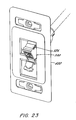
- FIG. 23 is a perspective view of the outlet 300 mounted in a faceplate 400.
- the opening of the outlet 300 is at an angle relative to the faceplate. This angle is established by notch 314 on the outlet top cover 302 and notch 315 on the outlet core 306 lying in a plane at an oblique angle relative to the face 317 of the outlet. As noted previously, this creates a gravity feed orientation in which the cable connected to a plug mated with outlet 300 is angled towards the floor thereby reducing the bend on the cable. This reduces the likelihood that the cable will be bent below the minimum bend radius.
- the identification icon 324 also serves as a lock securing the outlet 300 in the faceplate 400.
- FIG. 24 is a perspective view of the plug 100 mated with the outlet 300. Lip 120 engages recess 326 to secure plug 100 to outlet 300.
- the outlet 300 can also be mounted in a flat configuration in which the face of the outlet is parallel to the faceplate 400 as described above.
- FIGS. 25-32 illustrate the overlapping shield joints.
- FIG. 25 is a side view of plug 100.
- FIG. 26 is a cross-sectional view taken along line 26--26 of FIG. 25 and shows the overlap between various plug shield members.
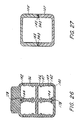
- FIG. 27 is a cross sectional view taken along line 27--27 of FIG. 25.
- Outlet 300 is similar to plug 100 in that top cover 302 and bottom cover 304 includes channels 178 for receiving ridges 337 on second planar shield 336.
- the top cover 302 and bottom cover 304 include recesses 303 for receiving extensions 327 on outlet core side walls 326. Extensions 309 on outlet top cover 302 are received in recesses 313 in outlet bottom cover 304.
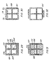
- FIG. 28 is a side view of the plug 100 mated to the outlet 300 and FIGS. 29-32 are cross-sectional views taken along FIG. 28.
- FIG. 29 illustrates the overlap between shield members in the outlet core and plug core.
- second planar shield member includes an offset rib 207 along its edge that overlaps shield extension 342.
- the offset rib 207 also provides a keying function so that the plug can only be installed in outlet 300 in one orientation.
- first planar shield 132 includes an offset rib 209 on its edge for engaging channel 338 which also provides keying.
- FIG. 30 illustrates the overlap between the outlet core, the outlet top cover and the outlet bottom cover.
- FIG. 31 is a cross sectional view of the junction between the plug and the outlet showing how the outlet top wall 319 and outlet side walls 328 overlap the front face 103 of the plug 100.
- FIG. 32 is a cross-sectional view taken along line 32--32 of FIG. 28 showing the bottom cover lip 165 which extends under outlet core bottom wall 332. Accordingly, each contact carrier is enclosed in a quadrant where all shield joints have some overlap and the amount of shielding between pairs is enhanced as compared to a shield arrangement using butt joints.
- FIG. 33 is a perspective view of an assembled plug of a first alternative embodiment in accordance with the present invention, shown generally as 500.
- Plug 500 is similar to plug 100 but includes two pairs of contacts, instead of four pairs of contacts.
- the plug 500 includes a top cover 502, a bottom cover 504 and a core 506.
- the top cover 502, bottom cover 504 and core 506 are all conductive to provide shielding as described herein. These conductive components may be made from metal, metallized plastic or any other known conductive material.
- Core 506 supports insulative (e.g. plastic) contact carriers 508. Each contact carrier 508 includes two contacts 510 defining a pair.
- a boot 512 provides strain relief and is made from a pliable plastic or rubber.
- Also shown in FIG. 33 is cable 514 entering boot 512.
- a latch 516 is provided on the top cover 502 for mechanically connecting the plug 500 to outlet 700 and electrically connecting the cable ground layer to the outlet 700 as described herein.
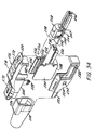
- FIG. 34 is an exploded, perspective view of the plug 500.
- Latch 516 is conductive (e.g. metal) and is made up of a latch body 518 secured to the top cover 502 at latch engaging pawl 570 and latch engaging post 572. A portion of the latch body 518 comprises a latch extension 524 for engaging an opening 740 formed in outlet 700. In addition to securing the plug 500 to the outlet 700, latch extension 524 allows for electrical contact from the cable ground layer to outlet core 706 in the outlet 700.
- Top cover 502 includes a semi-circular groove 526 and bottom cover 504 includes a similar semi-circular groove 526 that receives a circular lip 513 (FIG. 37) in boot 512 as described below.
- Two top cover latches 528 engage two bottom cover recesses 530 to secure top cover 502 to bottom cover 504.
- Plug core 506 includes a planar shield 532.
- Plug core 506 also includes side walls 534.
- the top portion 536 and bottom portion 538 of the side walls 534 serve to locate the core 506 within the top cover 502 and bottom cover 504 and overlap the edges of the top cover 502 and bottom cover 504 to provide better shielding than a butt joint.
- Two ribs 552 are formed on the inside surface of each side wall 534 and are parallel to and spaced apart from planar shield 532.
- Contact carrier 508 has a planar base 542 which rests on the planar shield 532.
- Base 542 includes two flanges 544 extending away from the base 542 wherein flange 544 has an incline portion 545 at one end and a stop 547 at the opposite end.
- contact carrier 508 When contact carrier 508 is installed in the core 506, flange 544 is placed under rib 552 to hold the contact carrier 508 to the planar shield 532. The contact carrier 508 is slid into the core 506 until stop 547 contacts the end of rib 552. In this position, a tab 546 is provided so that when contact carrier 508 is slid into core 506, tab 546 contacts a similarly shaped recess in planar shield 532 and positions contact carrier 508 in core 506.
- the contact carrier 508 also includes a lip 603 (shown in FIG. 36B) that extends substantially perpendicular to planar base 542 and beyond the edge of planar shield 532 to prevent the contact carrier 508 from sliding out of core 506.
- Recesses 550 are provided in planar shield 532 to receive ribs 736 on the side walls of outlet 700 and provide an overlap between the side walls of outlet 700 and planar shield 532.
- the inside of each side wall 534 also includes a first ledge 556 and a second ledge 554 which are used to secure a termination cap 558 as described below with reference to FIGS. 36-39.
- FIG. 35 is an exploded, perspective view of the top cover 502 and latch 516.
- the latch 516 includes a shield contact 560 which electrically connects the ground layer of cable 514 to the outlet core 706 of outlet 700.
- Shield contact 560 is conductive and is preferably made from metal.
- Shield contact 560 has an arcuate portion 562 formed to generally follow the shape of cable 514.
- Arcuate portion 562 includes barbs 564 that pierce the ground layer of cable 514 and the cable jacket. This electrically and mechanically connects the shield contact 560 to cable 514.
- arcuate portion 562 fits underneath neck 573 of top cover 502.
- Latch 516 When assembled, arcuate portion 560 is positioned within the interior of the plug 500 and the remainder of latch 516 is positioned outside of the plug 500.
- Latch 516 includes a first receiving opening 566 and a second receiving opening 568 formed within the latch body 518.
- First opening 566 is for receiving a pawl 570 formed in top cover 502 and second opening 568 is for receiving a post 572 formed in top cover 502.
- Post 572 includes a neck portion 574 and a head portion 576.
- First receiving opening 566 has a slot 567 and second receiving opening 568 has a slot 569 for engaging the neck 571 of pawl 570 and neck 574 of post 572, respectively.
- Latch 516 is engaged with top cover 502 by aligning first receiving opening 566 with the chamfered surface of pawl 570 and aligning the second receiving opening 568 with the head portion 576 of post 572 and then sliding the latch 516 in the direction toward post 572 so that neck 571 of pawl 570 slidably engages with slot 567 and neck 574 of post 572 slidably engages with slot 569.
- Top cover 502 also includes a nub 578 positioned beneath latch 516. Projections 582 engage a similarly shaped recesses 584 in side walls 534. Nub 578 is formed on top cover 502 beneath body portion 518 to limit travel of the latch 516 towards the top cover 502.
- Top cover 502 includes side recesses 583 for receiving and engaging with side walls 534, wherein the recesses 583 include a ridge having an incline portion 588 (FIG. 36A) and a land 590 (FIG. 36A), wherein side walls 534 are received on the ridge portion and the incline portion of said ridge causes side walls 534 to ride onto the land thereby coupling the two together in an overlapping manner.
- the recesses 583 include a ridge having an incline portion 588 (FIG. 36A) and a land 590 (FIG. 36A), wherein side walls 534 are received on the ridge portion and the incline portion of said ridge causes side walls 534 to ride onto the land thereby coupling the two together in an overlapping manner.
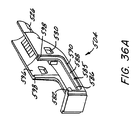
- FIG. 36A is a perspective view of the bottom cover 504.
- Bottom cover 504 includes a recess 585 similar to recess 583 in top cover 506 wherein recess 585 comprises a ledge 586, a ledge incline 588 and a land 590 for receiving side walls 534 of core 506. Side walls 534 are received at ledge 586 and side walls 534 ride on ledge incline 588 to land 590. This allows the side walls 534 to be overlapped by recess 584 of the bottom cover 504.
- Bottom cover 508 also includes a projection 582 for engaging similarly shaped recess 584 in each of side walls 534.
- Bottom cover includes side walls 596 having side wall recess 598 with a shoulder portion, similar to those on top cover 506, for receiving side walls 534 thereby allowing overlapping of the side walls 534 and the bottom cover 508 when side walls 534 abut the shoulder portion.
- Bottom cover 504 may include a lip 165 as described above with reference to plug 100 to overlap the bottom of outlet 700.
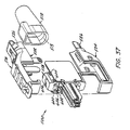
- FIG. 36B is an exploded, perspective view of the plug 500 including termination caps 558.
- a termination cap is provided for each pair of contacts.
- a termination cap forces wires onto an insulation displacement contact to pierce the insulation and electrically connect the wire and the insulation displacement contact.
- Termination cap 558 includes a first lip 600 and a second lip 602 that straddle ledges 554 and 556 on the plug core 506.
- the first lip 600 and second lip 602 have a beveled surface and first ledge 556 and second ledge 554 similarly have a beveled surface to facilitate installation of the termination cap 558 as disclosed below.
- Each termination cap 558 also includes a contact opening 604 for receiving the insulation displacement contacts 184 (shown in FIG.
- Termination caps 558 are positioned in the plug core 506 and retained in a first position.
- First lip 600 rests upon first ledge 556 to hold the termination cap 558 in a first position and second lip 602 is positioned beneath first ledge 556 to prevent termination cap 558 from being inadvertently removed from the plug core 506.
- FIG. 37 is another exploded, perspective view of the plug 500. As shown in FIG. 37, each termination cap 558 is in the first position by virtue of first lip 600 and second lip 602 straddling first ledge 556.
- Boot 512 includes a cylindrical lip 513 that engages groove 526 in the top cover 502 and the bottom cover 504.
- cable 514 includes four wires 608. Each pair of wires 608 is encased by a wire pair shield 610. Ground layer 612 is also housed within cable 514 and is pulled back over the outside jacket of cable 514. Wires 608 are inserted into wire openings 606 in termination caps 558. As described above, each wire opening 606 is aligned with an insulation contact 184 and thus each wire is positioned above an insulation displacement contact 184 (shown in FIG. 5). It is understood that boot 512 is placed over cable 514 prior to inserting the wires into termination caps 558.
- FIG. 39 shows the termination caps 558 in a second position.
- First lip 600 and second lip 602 now straddle second ledge 554 to hold the termination cap 558 in the second position.
- the wires 608 positioned in wire openings 606 are driven onto insulation displacement contacts 184.
- the insulation displacement contacts 184 split the insulation on each wire 608 thereby making electrical contact between the wires 608 and the contacts 160.
- An important aspect of the invention shown in FIG. 39 is the use of a buffer zone 614.
- the length of the planar shield 532 extend beyond the rear of each termination cap 558 to establish a buffer zone 614. Each wire pair rests in the buffer zone 614.
- the buffer zone 614 is important because during installation, the wire pair shield 610 is removed so that individual wires can be inserted in wire openings 606. Even assuming the installer removed the exact recommended length of wire pair shield 610, a small amount of exposed wire will create cross talk between adjacent pairs at frequencies of greater than 600 MHZ. In non-ideal installations, the installer will remove too much of the wire pair shield 610. Thus, the buffer zone 614 reduces cross talk in ideal or non-ideal installations and enhances the connector performance.
- the buffer zone 614 should have a length, measured from the rear of the termination cap 558 greater than the length of exposed wire 608 (wire pair shield removed) in a worst case installation.
- top cover 502 and bottom cover 504 each include projections 582 that engage similarly shaped recesses 584 on plug core 506 to secure the top cover 502 and bottom cover 504 to plug core 506.
- top cover latches 528 engage bottom cover openings 530 to secure the top cover 502 to the bottom cover 504.
- Latch 516 is secured to top cover 502 by aligning pawl 570 with first receiving opening 566 and slidably engaging neck 571 with slot 567 wherein slot 567 is integrally connected with first receiving opening 566.
- latch 516 is shown in FIG. 40 in a first position in which latch body 518 abuts against the head portion 576 of post 572 by virtue of latch 516 being constructed of a resilient material and due to the interlocking of neck 571 with slot 567.
- Shield contact 560 of latch 516 is disposed under neck 616 of top cover 502 so that shield contact 560 engages cable 514. Barbs 564 on shield contact 560 penetrate the ground layer 612 and the cable jacket to mechanically and electrically connect the shield contact 560 to cable 514.
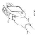
- the final step in the plug assembly is securing the boot 512 to the plug 500. As shown in FIG. 41, the boot 512 is snapped onto the top and bottom covers. Lip 513 on the inside surface of boot 512 engages the groove 526 formed in top cover 502 and bottom cover 504.
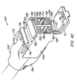
- FIG. 42 is a perspective view of an assembled outlet of a first alternative embodiment, shown generally as 700 wherein outlet 700 is for use with plug 500.
- Outlet 700 is similar to outlet 300 except that second planar shield 336 is replaced by vertical shield 732.
- the outlet 700 includes a top cover 702, bottom cover 704 and a core 706.
- the top cover 702, bottom cover 704, and core 706 are all conductive to provide shielding as described herein. These conductive components may be made from metal, metallized plastic or any other known conductive material.
- Core 706 supports insulative contact carriers 708. Each contact carrier includes contacts 710.
- An optional door 711 is also provided to prevent contamination (e.g. dust) from entering outlet 700.
- Top cover 702 includes a pair of resilient arms 712 having notches 714 formed therein. Notches 714 receive the edge of a faceplate as described with reference to FIG. 23. Another notch 715 is formed on the bottom of outlet core 706 for receiving another edge of the faceplate. Notches 714 and 715 lie in a plane that is at an oblique angle relative to the front face 717 of outlet 700. When mounted in a faceplate, this directs the outlet toward the ground and provides for a gravity feed design. The gravity feed reduces the bend angle of the cable connected to plug 500 and reduces the likelihood that the cable will be bent beyond the minimum bend radius and cause signal degradation or loss. Alternatively, notches 714 and 715 may lie in a plane parallel to the front face 717 of outlet 700.
- a member 716 connects the ends of resilient arms 714 and includes a recess 718 on a front face thereof Recess 718 receives one edge of an identification icon 724 (shown in FIG. 43).
- the identification icon 724 rests on support surface 720 and engages a recess 722. Both the support surface 720 and recess 722 are formed on the outlet core 706.
- the top cover 702 and bottom cover 704 of FIG. 42 are described herein with reference to FIGS. 14-16.
- the outlet core of FIG. 42 is generally rectangular and includes side walls 726, top wall 728, and bottom wall 730.
- One notable difference between outlet 300 of FIG. 13 and outlet 700 of FIG. 42 is a vertical planar shield 732 extending the entire length of outlet core 706 thereby dividing core 706 into a left and a right half for providing enhanced performance by isolation of the contact pairs. Each half is designed to receive a two-pair plug 500 of FIG. 33.
- Side walls 726 and vertical shield 732 include ribs 736 for engaging recesses 550 in planar shield 532 to create overlapping shield members.
- Opening 740 is designed to receive latch extension 524 of plug 500 and serves to lock plug 500 to outlet 700.
- Latch extension 524 is guided into opening 740 and as shown in FIG. 47, the underside of top wall 728 of outlet core 706 includes a lip 1200 for engaging opening 568 in latch extension 524.
- a beveled surface 1202 of the lip permits the latch extension 524 to slidably engage with the outlet core 706 by locking the latch extension 524 with a shoulder portion 1204 of the lip 1200.
- the latch 516 is pressed towards the top cover 502 to disengage opening 568 from lip 1200.
- the top cover 702, bottom cover 704 and core 706 of outlet 700 have overlapping joints to better isolate and shield the contact pairs so that enhanced performance results.
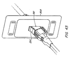
- FIG. 43 is a perspective view of two plugs 500 of FIG. 33 mated with outlet 700.
- outlet 700 is mounted in a faceplate 800.
- the opening of outlet 700 is at an angle relative to the faceplate. This angle is established by notch 714 on the outlet top cover 702 and notch 715 on the outlet core 706 lying in a plane at an oblique angle relative to the face 717 of the outlet. As noted previously, this creates a gravity feed orientation in which the cable connected to a plug mated with outlet 700 is angled towards the floor thereby reducing the bend on the cable. This reduces the likelihood that the cable will be bent below the minimum bend radius.
- the identification icon 724 also serves as a lock securing the outlet 700 in the faceplate 800.
- the resilient arms 712 are deflected until both notch 714 and notch 715 are aligned with the edge of the faceplate opening. At this point, arms 712 return to their original position.
- the identification icon 724 is positioned in recess 718 and recess 722, this prevents the arms 712 from deflecting towards outlet core 706 and thus locks the outlet 700 in position in the faceplate 800.
- the use of two-pair plugs 500 in outlet 700 occupies the same amount of space as the use of one four-pair plug 100 in outlet 300,
- the user may select whether to insert one or two plugs 500 in outlet 700 without the need for concern about whether said installation will require additional space.
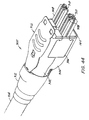
- FIG. 44 is a perspective view of an assembled plug of a second alternative embodiment in accordance with the present invention, shown generally at 900.
- Plug 900 mates with outlet 700 and is generally similar to plug 100 described herein but includes a space in the first planar shield for accommodating vertical shield 732 in outlet 700.
- the plug 900 includes a top cover 902, a bottom cover 904 and a core 906.
- the top cover 902, bottom cover 904 and core 906 are all conductive to provide shielding as described herein. These conductive components may be made from metal, metallized plastic or any other known conductive material.
- Core 906 supports insulative (e.g. plastic) contact carriers 908. Each contact carrier 908 includes two contacts 910 defining a pair.
- a boot 912 provides strain relief and is made from a pliable plastic or rubber. Also shown in FIG. 44 is a cable 914 entering boot 912. A latch 916 is provided on the top cover 902 for coupling the plug 900 to the outlet 700 of FIG. 42 and described herein.
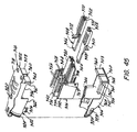
- FIG. 45 is an exploded, perspective view of an alternative plug 900.
- Plug 900 is similar to plug 100 in that it includes four pairs of contacts.
- the first planar shield 930 i.e. horizontal
- Latch 916 is made up of a latch body 918 secured to the top cover at latch engaging pawl 920.
- Latch 916 includes a latch extension 922 for engaging opening 740 formed in outlet 700.
- latch extension 922 provides for electrical contact from the cable ground layer to the outlet core 706.
- Top cover 902 includes a semi-circular groove 924 and bottom cover 904 includes a similar semi-circular groove 924 that receives a circular lip in boot 912 (shown generally at 513 on boot 512 in FIG. 37) as described herein.
- Two top cover latches 926 engage two bottom recesses 928 to secure top cover 902 to bottom cover 904.
- Plug core 906 includes a planar shield 930. Formed in planar shield 930 are recesses 909 (similar to recess 550) to receive ribs 736 in the outlet 700 to which plug 900 is mated. Plug core 906 also includes side walls 932. The top and bottom of each side wall 932 include a ridge 934. Ridges 934 extend beyond side wall 932 and overlap an edge 936 of the top cover 902 and bottom cover 904. Ridges 934 are shown as having generally triangular cross section, but it is understood that different geometries may be used without departing from the scope of the invention. Ridges 934 serve to locate the core 906 within the top and bottom covers and overlap the edges of the top and bottom cover to provide better shielding than a butt joint.
- a center shield 938 is provided within the core 906. Center shield 938 is parallel to side walls 932.
- the center shield 938 also includes a ridge 940 on the top and bottom surfaces. As shown in FIG. 45, central ridge 940 is triangular, however, it is understood that other geometries may be used without departing from the invention. Central ridge 940 engages channels 942 formed in top cover 902 and bottom cover 904.
- Two ribs 944 are formed on the inside surface of each side wall 932 and are parallel and spaced apart from planar shield 930. Similar ribs are formed on each surface of center shield 938.
- Contact carrier 908 has a planar base 946 which rests on the planar shield 930.
- Base 946 includes two flanges 948 extending away from the base and a stop 950 adjacent to the flanges.
- each side wall 932 and each side of center wall 938 also include a first ledge 956 and a second ledge 958 which are used to secure a termination cap to the plug core 906. Similar to the bottom cover 904, a channel (not shown) is formed in the top cover 902 for receiving ridge 940 of center shield 938 on plug core 906.
- the front face 903 of plug 900 also includes three recessed areas 960 that receive extensions on the front face 717 of outlet 700 as described herein.
- Top cover 902 includes side wall recesses for receiving rear extensions on plug core 906 to create an overlap between the rear of plug core side wall 932 and the plug core top cover (not shown).
- plug 900 also contains similar overlapping between wall extensions (not shown) on the side walls 962 of the top cover 902 and the outlet side wall recesses which engage each other to create overlap between the side walls 962 of the top plug cover 902 and the side walls 964 of the bottom cover 904.
- Bottom cover 904 and top cover 902 include projections 961 to engage similarly shaped recess 963 in side walls 932 of core 906.
- Bottom cover 904 is similar to top cover 902.
- Bottom cover also includes a channel 942 for receiving ridge 940 on center shield 938. As noted above, this allows the central ridge 940 to be overlapped by the sides of the channel 942 and provides better shielding than a conventional butt joint.
- Bottom cover 904 includes side walls 964 having side wall recesses 966 for receiving side wall extensions (not shown) on top cover 902.
- the front face 903 of the bottom cover 904 is similar to that of top cover 902 and includes recesses 960 for receiving the vertical planar shield 732 of the outlet 700 whereby front face 903 of plug 900 engages with the vertical planar shield 732 in an overlapping manner.
- the front face 903 of bottom cover 904 also includes as lip 968, interrupted by recess 960, that overlaps the outside surface of the bottom wall 730 of the outlet core 706.
- Contact carrier 908 includes two channels 970, each of which receives a contact 972.
- Each contact 972 has a generally planar body, a contact end and a termination end (as shown in FIG. 5).
- the termination end includes an insulation displacement contact that pierces the insulation of individual wires in cable 914 to make an electrical contact with the wire as is known in the art. Installation of the wires in the insulation displacement contact is described herein with reference to FIGS. 8-10.
- Each insulation displacement contact is angled relative to the longitudinal axis of the contact body at an angle of 45 degrees.
- the plug 900 includes four contact carriers 908, each having a pair of contacts 972 for a total of eight contacts.
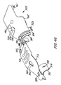
- FIG. 46 is an exploded, perspective view of the top cover 902 and latch 916.
- Latch 916 includes a shield contact 974 which electrically connects the ground layer of cable 914 to the outlet core 706 of outlet 700.
- Shield contact 974 is conductive and is preferably made from metal.
- Shield contact 974 has an arcuate portion 976 formed to generally follow the shape of cable 914.
- Arcuate portion 976 includes barbs 978 that pierce the ground layer of cable 914 and the cable jacket. This electrically and mechanically connects the shield contact 974 to cable 914.
- Latch 916 includes a first opening 982, a second opening 984 having a slot 986 integrally connected thereto, and a pair of third openings 988.
- First opening 982 is for receiving pawl 990 formed in top cover 902 and second opening 984 is for receiving post 920 formed in top cover 902.
- Post 920 includes a neck 992 and a head 994.
- Top cover 902 Integrally connected to second opening 984 is a slot 986 for engaging neck 992 of post 920.
- Latch 916 is engaged with top cover 902 by aligning head 994 of post 920 with second opening 984 and aligning pawl 990 with first opening 982 and sliding the latch 916 in the direction toward post 920 so that neck 992 of post 920 slidably engages with slot 986 and pawl 990 is disposed within first opening 982.
- Top cover 902 also includes a pair of nubs 996 formed on top cover 902 wherein the latch body 918 contacts nubs 996 when the latch body 918 is pressed towards the top cover 902. Openings 988 engage lips 1200 formed in housing 700 as described above.
- FIGS. 47-48 illustrate the overlapping of components.
- FIG. 47 is a side view of plug 900 and outlet 700.
- FIG. 48 is a cross-sectional view taken along line 48--48 of FIG. 47 and shows the overlap between various plug shield members and the outlet 700.
- Ribs 736 on outlet side wall 726 serve to secure plug 900 to outlet core 706.
- Ribs 736 serve to engage recesses 909 formed in planar shield 930 of plug 900 to allow planar shield to slidably enter outlet core 706 and be securely coupled to outlet core 706.
- Ribs 340 are formed on outlet side walls 726 and on vertical planar shield 732 of outlet core 706 to hold the contact carriers 708.
- each contact carrier is enclosed in a quadrant where all shield joints have some overlap and the amount of shielding between pairs is enhanced as compared to a shield arrangement using butt joints.
- the vertical planar shield 732 of outlet 700 and the planar shield 930 of plug 900 create the four quadrant system shown in FIG. 48, wherein each contact carrier is enclosed in a separate quadrant having the enhanced shielding characteristics disclosed herein.
Landscapes
- Details Of Connecting Devices For Male And Female Coupling (AREA)
- Connector Housings Or Holding Contact Members (AREA)
- Coupling Device And Connection With Printed Circuit (AREA)
- Multi-Conductor Connections (AREA)
Applications Claiming Priority (3)
| Application Number | Priority Date | Filing Date | Title |
|---|---|---|---|
| US09/007,313 US6328601B1 (en) | 1998-01-15 | 1998-01-15 | Enhanced performance telecommunications connector |
| US7313 | 1998-01-15 | ||
| EP98946962A EP0966776B1 (de) | 1998-01-15 | 1998-09-14 | Telekommunikationstecker mit verbesserter leistung |
Related Parent Applications (1)
| Application Number | Title | Priority Date | Filing Date |
|---|---|---|---|
| EP98946962A Division EP0966776B1 (de) | 1998-01-15 | 1998-09-14 | Telekommunikationstecker mit verbesserter leistung |
Publications (3)
| Publication Number | Publication Date |
|---|---|
| EP1538715A2 true EP1538715A2 (de) | 2005-06-08 |
| EP1538715A3 EP1538715A3 (de) | 2005-06-15 |
| EP1538715B1 EP1538715B1 (de) | 2006-08-16 |
Family
ID=21725445
Family Applications (1)
| Application Number | Title | Priority Date | Filing Date |
|---|---|---|---|
| EP05001920A Expired - Lifetime EP1538715B1 (de) | 1998-01-15 | 1998-09-14 | Telekommunikationsverbinder mit verbesserter Leistung |
Country Status (5)
| Country | Link |
|---|---|
| US (2) | US6328601B1 (de) |
| EP (1) | EP1538715B1 (de) |
| DE (1) | DE69835630T2 (de) |
| DK (1) | DK1538715T3 (de) |
| ES (1) | ES2271915T3 (de) |
Cited By (3)
| Publication number | Priority date | Publication date | Assignee | Title |
|---|---|---|---|---|
| WO2011087899A1 (en) * | 2010-01-15 | 2011-07-21 | Tyco Electronics Corporation | Plug assembly |
| EP2410620A1 (de) * | 2010-07-19 | 2012-01-25 | Tyco Electronics Corporation | Kabelschelle für eine Steckeranordnung |
| CN105789988A (zh) * | 2015-04-28 | 2016-07-20 | 昆山全方位电子科技有限公司 | 一种电连接器 |
Families Citing this family (99)
| Publication number | Priority date | Publication date | Assignee | Title |
|---|---|---|---|---|
| DE69915340T2 (de) | 1998-11-30 | 2004-07-22 | The Siemon Co., Watertown | Vorbereitungswerkzeug für abgeschirmte kabel |
| US6431904B1 (en) * | 1999-05-28 | 2002-08-13 | Krone, Inc. | Cable assembly with molded stress relief and method for making the same |
| US6506077B2 (en) * | 2000-07-21 | 2003-01-14 | The Siemon Company | Shielded telecommunications connector |
| USD456358S1 (en) | 2000-08-10 | 2002-04-30 | Instrumentarium Corp. | Electrical connector |
| US6572272B2 (en) * | 2000-11-29 | 2003-06-03 | Berg Technology, Inc. | Angled optical connector mounting assembly |
| US6394824B1 (en) * | 2001-04-04 | 2002-05-28 | Hon Hai Precision Ind. Co., Ltd. | Electrical connector |
| US6454577B1 (en) * | 2001-10-19 | 2002-09-24 | Hon Hai Precision Ind. Co., Ltd. | Electrical connector having device for latching and grounding |
| US6485315B1 (en) * | 2001-12-20 | 2002-11-26 | Hon Hai Precision Ind. Co., Ltd. | Electrical plug connector with spring latch and grounding tabs |
| US6761589B2 (en) | 2002-01-18 | 2004-07-13 | Ortronics, Inc. | Patch plug design and methods for use thereof |
| US7037129B2 (en) * | 2002-04-26 | 2006-05-02 | The Siemon Company | Axial latch actuator with locking wedge |
| CN101167219B (zh) * | 2002-04-26 | 2011-04-13 | 西蒙公司 | 轴向弹锁致动器 |
| US6905367B2 (en) * | 2002-07-16 | 2005-06-14 | Silicon Bandwidth, Inc. | Modular coaxial electrical interconnect system having a modular frame and electrically shielded signal paths and a method of making the same |
| US6702617B1 (en) * | 2002-08-22 | 2004-03-09 | International Business Machines Corporation | Electrical connector with geometrical continuity for transmitting very high frequency data signals |
| ATE317160T1 (de) * | 2002-09-05 | 2006-02-15 | Schaffner Emv Ag | Durchführungsklemme |
| NL1022225C2 (nl) * | 2002-12-20 | 2004-06-22 | Framatome Connectors Int | Kabelconnector en werkwijze voor het samenvoegen van een kabel en een dergelijke kabelconnector. |
| US6974911B2 (en) * | 2003-05-09 | 2005-12-13 | Electec Limited | Modular wiring system |
| US6918782B2 (en) * | 2003-10-08 | 2005-07-19 | The Siemon Company | Modular plug with locking member |
| CN100429829C (zh) * | 2003-11-19 | 2008-10-29 | 西蒙公司 | 电缆屏蔽层接触件 |
| EP2284963A1 (de) * | 2004-10-22 | 2011-02-16 | Panduit Corp. | Gegentakt-Stecker und Werkzeuge |
| US7695197B2 (en) * | 2006-04-20 | 2010-04-13 | Tyco Electronics Corporation | Bend limiter |
| US7568950B2 (en) * | 2006-05-17 | 2009-08-04 | Bel Fuse Ltd. | High speed modular jack including multiple contact blocks and method for assembling same |
| US7753717B2 (en) | 2006-05-17 | 2010-07-13 | Bel Fuse Ltd. | High speed data plug and method for assembly |
| US20070270044A1 (en) * | 2006-05-17 | 2007-11-22 | Yakov Belopolsky | High Speed Modular Jack |
| GB0625061D0 (en) * | 2006-12-15 | 2007-01-24 | Tyco Electronics Amp Es Sa | A connector for use in terminating communications cables |
| US7753713B2 (en) * | 2007-06-12 | 2010-07-13 | Delphi Technologies, Inc. | Universal serial bus standard interface connections |
| US7727025B2 (en) * | 2007-10-09 | 2010-06-01 | Tyco Electronics Corporation | Modular electrical connector with enhanced plug interface |
| US7785140B2 (en) * | 2008-09-16 | 2010-08-31 | Tyco Electronics Corporation | Modular electrical connector with opposing contact support members |
| TWM359851U (en) * | 2008-12-12 | 2009-06-21 | Lan Accessories Co Ltd | Anti-loose and fixing device for connector |
| US7727034B1 (en) * | 2009-05-22 | 2010-06-01 | Lisong Liu | Connector for connecting printed surface area or line with conductive wire |
| WO2011140438A2 (en) * | 2010-05-07 | 2011-11-10 | Amphenol Corporation | High performance cable connector |
| WO2012078824A2 (en) | 2010-12-07 | 2012-06-14 | Carlyle, Inc. D/B/A Carlisle Interconnect Technologies | Electrical connector for high-speed data transmission |
| EP2466697B1 (de) * | 2010-12-17 | 2020-01-22 | LEONI Kabel GmbH | Datenkabelanschlussmodul sowie ein Verfahren zu dessen Konfektion an einem Kabel |
| US9450326B2 (en) | 2010-12-17 | 2016-09-20 | Leoni Kabel Holding Gmbh | Data cable connector module for assembly to cable with a fixation element for positioning and fixing of cable conductors of a multi core cable |
| WO2012177486A2 (en) * | 2011-06-21 | 2012-12-27 | Adc Telecommunications, Inc. | Connector with cable retention feature and patch cord having the same |
| DE102011055750B3 (de) * | 2011-11-28 | 2013-02-14 | Harting Kgaa | Isolierkörper eines Steckverbinders |
| US8926366B2 (en) | 2012-03-26 | 2015-01-06 | Carlisle Interconnect Technologies, Inc. | PCB-mount electrical connector with shielding for inhibiting crosstalk |
| US9033725B2 (en) | 2012-04-19 | 2015-05-19 | Panduit Corp. | GG45 plug with hinging load bar |
| US9831588B2 (en) | 2012-08-22 | 2017-11-28 | Amphenol Corporation | High-frequency electrical connector |
| US9306333B2 (en) | 2012-10-29 | 2016-04-05 | Carlisle Interconnect Technologies, Inc. | High density sealed electrical connector with grounding contact for improved mechanical connection and shielding |
| US9306312B2 (en) | 2012-10-29 | 2016-04-05 | Carlisle Interconnect Technologies, Inc. | High density sealed electrical connector with multiple shielding strain relief devices |
| JP5952749B2 (ja) * | 2013-01-28 | 2016-07-13 | ホシデン株式会社 | コネクタおよびこれに接続可能な相手側コネクタ |
| US8979592B2 (en) | 2013-03-15 | 2015-03-17 | Carlisle Interconnect Technologies, Inc. | Electrical connector for high-speed data transmission |
| DE202013006295U1 (de) * | 2013-07-11 | 2013-09-05 | Rosenberger Hochfrequenztechnik Gmbh & Co. Kg | System mit mehreren Steckverbindern und Mehrfachsteckverbinder |
| US9362659B2 (en) * | 2013-12-10 | 2016-06-07 | Delphi Technologies, Inc. | Electrical connector terminal |
| DE102013114478B4 (de) * | 2013-12-19 | 2018-10-25 | Phoenix Contact Gmbh & Co. Kg | Steckverbinderbaugruppe mit einem Deckel |
| CN112234393B (zh) | 2014-01-22 | 2022-09-13 | 安费诺有限公司 | 电连接器、线缆组件、电气组件以及印刷电路板 |
| EP3134945B1 (de) | 2014-04-23 | 2019-06-12 | TE Connectivity Corporation | Elektrischer steckverbinder mit abschirmungskappe und abgeschirmte anschlüsse |
| US9685736B2 (en) | 2014-11-12 | 2017-06-20 | Amphenol Corporation | Very high speed, high density electrical interconnection system with impedance control in mating region |
| JP6429078B2 (ja) * | 2015-01-29 | 2018-11-28 | 株式会社オートネットワーク技術研究所 | シールドコネクタ |
| WO2017007429A1 (en) | 2015-07-07 | 2017-01-12 | Amphenol Fci Asia Pte. Ltd. | Electrical connector |
| TWI871571B (zh) | 2015-07-23 | 2025-02-01 | 美商安芬諾Tcs公司 | 連接器、製造連接器方法、用於連接器的擴充器模組以及電子系統 |
| JP6455361B2 (ja) | 2015-08-20 | 2019-01-23 | 株式会社オートネットワーク技術研究所 | 通信用コネクタ及び電線付き通信用コネクタ |
| JP6443274B2 (ja) | 2015-09-09 | 2018-12-26 | 株式会社オートネットワーク技術研究所 | 通信用コネクタ及び電線付き通信用コネクタ |
| CN109980409B (zh) * | 2016-04-28 | 2020-08-21 | 深圳市秦通科技有限公司 | 能够适应多种线径的水晶头及通讯缆线 |
| CN105811181B (zh) * | 2016-04-28 | 2018-06-29 | 深圳市秦通科技有限公司 | 具有金属屏蔽罩的水晶头及通讯缆线 |
| TWI790785B (zh) | 2016-05-31 | 2023-01-21 | 美商安芬諾股份有限公司 | 電終端、纜線總成以及纜線端接方法 |
| CN109155491B (zh) | 2016-06-01 | 2020-10-23 | 安费诺Fci连接器新加坡私人有限公司 | 高速电连接器 |
| WO2018039164A1 (en) | 2016-08-23 | 2018-03-01 | Amphenol Corporation | Connector configurable for high performance |
| CN110088985B (zh) | 2016-10-19 | 2022-07-05 | 安费诺有限公司 | 用于超高速高密度电互连的柔性屏蔽件 |
| TW202510437A (zh) | 2017-08-03 | 2025-03-01 | 美商安芬諾股份有限公司 | 電纜總成及電子系統中的電纜總成 |
| CN111512499B (zh) | 2017-10-30 | 2022-03-08 | 安费诺富加宜(亚洲)私人有限公司 | 低串扰卡缘连接器 |
| US10601181B2 (en) | 2017-12-01 | 2020-03-24 | Amphenol East Asia Ltd. | Compact electrical connector |
| US10777921B2 (en) | 2017-12-06 | 2020-09-15 | Amphenol East Asia Ltd. | High speed card edge connector |
| US10665973B2 (en) | 2018-03-22 | 2020-05-26 | Amphenol Corporation | High density electrical connector |
| CN112514175B (zh) | 2018-04-02 | 2022-09-09 | 安达概念股份有限公司 | 受控阻抗顺应性线缆终端头 |
| CN208862209U (zh) | 2018-09-26 | 2019-05-14 | 安费诺东亚电子科技(深圳)有限公司 | 一种连接器及其应用的pcb板 |
| WO2020073460A1 (en) | 2018-10-09 | 2020-04-16 | Amphenol Commercial Products (Chengdu) Co. Ltd. | High-density edge connector |
| TWM576774U (zh) | 2018-11-15 | 2019-04-11 | 香港商安費諾(東亞)有限公司 | 具有防位移結構之金屬殼體及其連接器 |
| US10931062B2 (en) | 2018-11-21 | 2021-02-23 | Amphenol Corporation | High-frequency electrical connector |
| US11114796B2 (en) | 2018-12-04 | 2021-09-07 | Carlisle Interconnect Technologies, Inc. | Electrical connector with modular housing for accommodating various contact layouts |
| US11381015B2 (en) | 2018-12-21 | 2022-07-05 | Amphenol East Asia Ltd. | Robust, miniaturized card edge connector |
| WO2020154507A1 (en) | 2019-01-25 | 2020-07-30 | Fci Usa Llc | I/o connector configured for cable connection to a midboard |
| WO2020154526A1 (en) | 2019-01-25 | 2020-07-30 | Fci Usa Llc | I/o connector configured for cabled connection to the midboard |
| US11189971B2 (en) | 2019-02-14 | 2021-11-30 | Amphenol East Asia Ltd. | Robust, high-frequency electrical connector |
| TWI889666B (zh) | 2019-02-19 | 2025-07-11 | 美商安芬諾股份有限公司 | 電連接器及用於製造電連接器之方法 |
| CN113728521B (zh) | 2019-02-22 | 2025-03-18 | 安费诺有限公司 | 高性能线缆连接器组件 |
| TWM582251U (zh) | 2019-04-22 | 2019-08-11 | 香港商安費諾(東亞)有限公司 | Connector set with built-in locking mechanism and socket connector thereof |
| TWI855075B (zh) | 2019-05-20 | 2024-09-11 | 美商安芬諾股份有限公司 | 連接器模組、連接器、電子組件、電連接器以及連接器模組的薄片 |
| EP3758163A1 (de) * | 2019-06-24 | 2020-12-30 | TE Connectivity Nederland B.V. | Steckereinsatz für eine verbinderanordnung und verbinderanordnung |
| US11228132B2 (en) * | 2019-07-01 | 2022-01-18 | Panduit Corp. | Single pair ethernet field terminable connector |
| US11735852B2 (en) | 2019-09-19 | 2023-08-22 | Amphenol Corporation | High speed electronic system with midboard cable connector |
| US11799230B2 (en) | 2019-11-06 | 2023-10-24 | Amphenol East Asia Ltd. | High-frequency electrical connector with in interlocking segments |
| US11588277B2 (en) | 2019-11-06 | 2023-02-21 | Amphenol East Asia Ltd. | High-frequency electrical connector with lossy member |
| US11469554B2 (en) | 2020-01-27 | 2022-10-11 | Fci Usa Llc | High speed, high density direct mate orthogonal connector |
| WO2021154702A1 (en) | 2020-01-27 | 2021-08-05 | Fci Usa Llc | High speed connector |
| CN113258325A (zh) | 2020-01-28 | 2021-08-13 | 富加宜(美国)有限责任公司 | 高频中板连接器 |
| TWM630230U (zh) | 2020-03-13 | 2022-08-01 | 大陸商安費諾商用電子產品(成都)有限公司 | 加強部件、電連接器、電路板總成及絕緣本體 |
| US11728585B2 (en) | 2020-06-17 | 2023-08-15 | Amphenol East Asia Ltd. | Compact electrical connector with shell bounding spaces for receiving mating protrusions |
| US11831092B2 (en) | 2020-07-28 | 2023-11-28 | Amphenol East Asia Ltd. | Compact electrical connector |
| US11652307B2 (en) | 2020-08-20 | 2023-05-16 | Amphenol East Asia Electronic Technology (Shenzhen) Co., Ltd. | High speed connector |
| CN212874843U (zh) | 2020-08-31 | 2021-04-02 | 安费诺商用电子产品(成都)有限公司 | 电连接器 |
| CN215816516U (zh) | 2020-09-22 | 2022-02-11 | 安费诺商用电子产品(成都)有限公司 | 电连接器 |
| CN213636403U (zh) | 2020-09-25 | 2021-07-06 | 安费诺商用电子产品(成都)有限公司 | 电连接器 |
| US11569613B2 (en) | 2021-04-19 | 2023-01-31 | Amphenol East Asia Ltd. | Electrical connector having symmetrical docking holes |
| US12176650B2 (en) | 2021-05-05 | 2024-12-24 | Amphenol East Asia Limited (Hong Kong) | Electrical connector with guiding structure and mating groove and method of connecting electrical connector |
| CN215266741U (zh) | 2021-08-13 | 2021-12-21 | 安费诺商用电子产品(成都)有限公司 | 一种满足高带宽传输的高性能卡类连接器 |
| USD1002553S1 (en) | 2021-11-03 | 2023-10-24 | Amphenol Corporation | Gasket for connector |
| USD1068685S1 (en) | 2021-12-14 | 2025-04-01 | Amphenol Corporation | Electrical connector |
| USD1067191S1 (en) | 2021-12-14 | 2025-03-18 | Amphenol Corporation | Electrical connector |
Family Cites Families (30)
| Publication number | Priority date | Publication date | Assignee | Title |
|---|---|---|---|---|
| US4337989A (en) | 1980-05-28 | 1982-07-06 | Amp Incorporated | Electromagnetic shielded connector |
| US4659163A (en) | 1984-06-13 | 1987-04-21 | Amp Incorporated | Filtered shielded connector assembly |
| US4602833A (en) * | 1984-12-20 | 1986-07-29 | Amp Incorporated | Closed loop connector |
| US4682836A (en) | 1985-10-07 | 1987-07-28 | Thomas & Betts Corporation | Electrical connector and cable termination apparatus therefor |
| JPH0719632B2 (ja) | 1986-05-29 | 1995-03-06 | アンプ インコ−ポレ−テツド | 多極シ−ルドコネクタ |
| CA1289211C (en) | 1986-11-18 | 1991-09-17 | Timothy A. Lemke | Terminator for multiple electrical conductors |
| US5057028A (en) | 1986-11-18 | 1991-10-15 | E. I. Du Pont De Nemours And Company | Receptacle having a nosepeice to receive cantilevered spring contacts |
| US4990094A (en) | 1987-12-21 | 1991-02-05 | Amp Incorporated | Data distribution panel |
| EP0368982B1 (de) | 1988-05-13 | 1996-09-25 | Connector Systems Technology N.V. | Steckverbindersystem für mehrere elektrische leiter |
| DE9015255U1 (de) | 1990-11-06 | 1991-02-14 | Siemens AG, 80333 München | Vielpoliger geschirmter Steckverbinder |
| US5102353A (en) | 1991-06-06 | 1992-04-07 | Molex Incorporated | Electrical connectors |
| US5518421A (en) * | 1993-01-26 | 1996-05-21 | The Whitaker Corporation | Two piece shell for a connector |
| US5531606A (en) * | 1993-02-04 | 1996-07-02 | Thomas & Betts Corporation | Shielded vertically aligned electrical connector components |
| US5376021A (en) | 1993-02-05 | 1994-12-27 | Thomas & Betts Corporation | Enhanced performance data connector |
| NL9300971A (nl) | 1993-06-04 | 1995-01-02 | Framatome Connectors Belgium | Connectorsamenstel voor printkaarten. |
| US5593311A (en) | 1993-07-14 | 1997-01-14 | Thomas & Betts Corporation | Shielded compact data connector |
| JPH07122335A (ja) * | 1993-10-20 | 1995-05-12 | Minnesota Mining & Mfg Co <3M> | 高速伝送用コネクタ |
| US5460545A (en) * | 1993-10-28 | 1995-10-24 | The Siemon Company | Patch connector |
| US5538440A (en) | 1993-11-17 | 1996-07-23 | Thomas & Betts Corporation | Electrical connector having a conductor holding block |
| US5681180A (en) | 1994-11-02 | 1997-10-28 | Thomas & Betts Corporation | Conductor holding block for an electrical connector |
| US5372513A (en) | 1993-11-17 | 1994-12-13 | Thomas & Betts Corporation | Electrical connector with cable shield ground clip |
| US5564949A (en) | 1995-01-05 | 1996-10-15 | Thomas & Betts Corporation | Shielded compact data connector |
| US5605469A (en) * | 1995-01-05 | 1997-02-25 | Thomas & Betts Corporation | Electrical connector having an improved conductor holding block and conductor shield |
| JP3126102B2 (ja) * | 1995-08-11 | 2001-01-22 | ヒロセ電機株式会社 | Pcカード用ソケットコネクタ及びこれを有するpcカード |
| NO301254B1 (no) | 1996-02-29 | 1997-09-29 | Telesafe As | Kontaktsett for kopling av parkabel til et kretskort |
| DK0809331T3 (da) | 1996-05-23 | 2000-01-17 | Bks Kabel Service Ag | Flerpolet stiksystem med en stikdåse og i det mindste et stik til elektrisk og mekanisk forbindelse af elektriske ledere |
| US5876248A (en) * | 1997-01-14 | 1999-03-02 | Molex Incorporated | Matable electrical connectors having signal and power terminals |
| FR2762453B1 (fr) | 1997-04-17 | 1999-06-25 | Soc D Fabrication Ind Et Mecan | Connecteur electrique pour frequences elevees |
| US6077122A (en) | 1997-10-30 | 2000-06-20 | Thomas & Bett International, Inc. | Electrical connector having an improved connector shield and a multi-purpose strain relief |
| US6045389A (en) | 1998-06-30 | 2000-04-04 | The Whitaker Corporation | Contact and connector for terminating a pair of individually insulated wires |
-
1998
- 1998-01-15 US US09/007,313 patent/US6328601B1/en not_active Expired - Lifetime
- 1998-03-24 US US09/047,046 patent/US6224423B1/en not_active Expired - Lifetime
- 1998-09-14 ES ES05001920T patent/ES2271915T3/es not_active Expired - Lifetime
- 1998-09-14 EP EP05001920A patent/EP1538715B1/de not_active Expired - Lifetime
- 1998-09-14 DK DK05001920T patent/DK1538715T3/da active
- 1998-09-14 DE DE69835630T patent/DE69835630T2/de not_active Expired - Lifetime
Cited By (6)
| Publication number | Priority date | Publication date | Assignee | Title |
|---|---|---|---|---|
| WO2011087899A1 (en) * | 2010-01-15 | 2011-07-21 | Tyco Electronics Corporation | Plug assembly |
| US8096833B2 (en) | 2010-01-15 | 2012-01-17 | Tyco Electronics Corporation | Plug assembly |
| EP2410620A1 (de) * | 2010-07-19 | 2012-01-25 | Tyco Electronics Corporation | Kabelschelle für eine Steckeranordnung |
| US8337238B2 (en) | 2010-07-19 | 2012-12-25 | Tyco Electronics Corporation | Cable clip for a connector assembly |
| CN105789988A (zh) * | 2015-04-28 | 2016-07-20 | 昆山全方位电子科技有限公司 | 一种电连接器 |
| CN105789988B (zh) * | 2015-04-28 | 2018-11-20 | 昆山全方位电子科技有限公司 | 一种电连接器 |
Also Published As
| Publication number | Publication date |
|---|---|
| US6224423B1 (en) | 2001-05-01 |
| ES2271915T3 (es) | 2007-04-16 |
| DE69835630T2 (de) | 2007-09-06 |
| US6328601B1 (en) | 2001-12-11 |
| DE69835630D1 (de) | 2006-09-28 |
| EP1538715A3 (de) | 2005-06-15 |
| DK1538715T3 (da) | 2007-01-15 |
| EP1538715B1 (de) | 2006-08-16 |
Similar Documents
| Publication | Publication Date | Title |
|---|---|---|
| EP1538715B1 (de) | Telekommunikationsverbinder mit verbesserter Leistung | |
| US6629858B2 (en) | Enhanced performance telecommunications connector | |
| EP0966776B1 (de) | Telekommunikationstecker mit verbesserter leistung | |
| US6171150B1 (en) | Connector | |
| US5059140A (en) | Shielded plug and jack connector | |
| US4781623A (en) | Shielded plug and jack connector | |
| US4508415A (en) | Shielded electrical connector for flat cable | |
| US5586911A (en) | Shielding data connector | |
| JP3362930B2 (ja) | コネクタ | |
| US4884981A (en) | Shielded data connector | |
| US6358092B1 (en) | Shielded telecommunications connector | |
| KR970004148B1 (ko) | 암수형 이중 잠금 커넥터 | |
| US6168466B1 (en) | Shielded electrical connector | |
| US6123582A (en) | Micro connector assembly with grounding shield | |
| EP1438770B1 (de) | Abgeschirmter telekommunikationsverbinder | |
| EP0473063A2 (de) | Umgossener abgeschirmter Verbinder | |
| JPH07201379A (ja) | パッチコネクタ | |
| US7371118B2 (en) | Electrical connector assembly with reduced crosstalk and electromaganetic interference | |
| US5944559A (en) | Shielded electrical connector | |
| US6179661B1 (en) | Electrical connector with a securely attached shield | |
| WO2000044070A2 (en) | Telecommunications connector | |
| US4941848A (en) | Shielded plug jack connector | |
| US6568959B1 (en) | Identification icon | |
| IL106494A (en) | Shielded data connector | |
| US6012943A (en) | Insulation displacement connector |
Legal Events
| Date | Code | Title | Description |
|---|---|---|---|
| PUAI | Public reference made under article 153(3) epc to a published international application that has entered the european phase |
Free format text: ORIGINAL CODE: 0009012 |
|
| PUAL | Search report despatched |
Free format text: ORIGINAL CODE: 0009013 |
|
| AC | Divisional application: reference to earlier application |
Ref document number: 0966776 Country of ref document: EP Kind code of ref document: P |
|
| AK | Designated contracting states |
Kind code of ref document: A2 Designated state(s): CH DE DK ES FR GB IT LI NL SE |
|
| AK | Designated contracting states |
Kind code of ref document: A3 Designated state(s): CH DE DK ES FR GB IT LI NL SE |
|
| RIN1 | Information on inventor provided before grant (corrected) |
Inventor name: BELOW, RANDY Inventor name: SIEMON, JOHN A. Inventor name: LO, DENNY Inventor name: YIP, MAXWELL |
|
| RIN1 | Information on inventor provided before grant (corrected) |
Inventor name: SIEMON, JOHN A. Inventor name: BELOW, RANDY Inventor name: YIP, MAXWELL Inventor name: LO, DENNY |
|
| 17P | Request for examination filed |
Effective date: 20051010 |
|
| GRAP | Despatch of communication of intention to grant a patent |
Free format text: ORIGINAL CODE: EPIDOSNIGR1 |
|
| AKX | Designation fees paid |
Designated state(s): CH DE DK ES FR GB IT LI NL SE |
|
| GRAS | Grant fee paid |
Free format text: ORIGINAL CODE: EPIDOSNIGR3 |
|
| GRAA | (expected) grant |
Free format text: ORIGINAL CODE: 0009210 |
|
| AC | Divisional application: reference to earlier application |
Ref document number: 0966776 Country of ref document: EP Kind code of ref document: P |
|
| AK | Designated contracting states |
Kind code of ref document: B1 Designated state(s): CH DE DK ES FR GB IT LI NL SE |
|
| REG | Reference to a national code |
Ref country code: GB Ref legal event code: FG4D |
|
| REG | Reference to a national code |
Ref country code: CH Ref legal event code: EP |
|
| REF | Corresponds to: |
Ref document number: 69835630 Country of ref document: DE Date of ref document: 20060928 Kind code of ref document: P |
|
| PGFP | Annual fee paid to national office [announced via postgrant information from national office to epo] |
Ref country code: IT Payment date: 20060930 Year of fee payment: 9 |
|
| PGFP | Annual fee paid to national office [announced via postgrant information from national office to epo] |
Ref country code: NL Payment date: 20061024 Year of fee payment: 9 |
|
| PGFP | Annual fee paid to national office [announced via postgrant information from national office to epo] |
Ref country code: ES Payment date: 20061026 Year of fee payment: 9 |
|
| PGFP | Annual fee paid to national office [announced via postgrant information from national office to epo] |
Ref country code: SE Payment date: 20061027 Year of fee payment: 9 |
|
| PGFP | Annual fee paid to national office [announced via postgrant information from national office to epo] |
Ref country code: DK Payment date: 20061030 Year of fee payment: 9 |
|
| REG | Reference to a national code |
Ref country code: SE Ref legal event code: TRGR |
|
| REG | Reference to a national code |
Ref country code: DK Ref legal event code: T3 |
|
| ET | Fr: translation filed | ||
| REG | Reference to a national code |
Ref country code: ES Ref legal event code: FG2A Ref document number: 2271915 Country of ref document: ES Kind code of ref document: T3 |
|
| PLBE | No opposition filed within time limit |
Free format text: ORIGINAL CODE: 0009261 |
|
| STAA | Information on the status of an ep patent application or granted ep patent |
Free format text: STATUS: NO OPPOSITION FILED WITHIN TIME LIMIT |
|
| 26N | No opposition filed |
Effective date: 20070518 |
|
| PG25 | Lapsed in a contracting state [announced via postgrant information from national office to epo] |
Ref country code: SE Free format text: LAPSE BECAUSE OF NON-PAYMENT OF DUE FEES Effective date: 20070915 |
|
| REG | Reference to a national code |
Ref country code: DK Ref legal event code: EBP |
|
| EUG | Se: european patent has lapsed | ||
| PG25 | Lapsed in a contracting state [announced via postgrant information from national office to epo] |
Ref country code: NL Free format text: LAPSE BECAUSE OF NON-PAYMENT OF DUE FEES Effective date: 20080401 |
|
| NLV4 | Nl: lapsed or anulled due to non-payment of the annual fee |
Effective date: 20080401 |
|
| PG25 | Lapsed in a contracting state [announced via postgrant information from national office to epo] |
Ref country code: DK Free format text: LAPSE BECAUSE OF NON-PAYMENT OF DUE FEES Effective date: 20071001 |
|
| REG | Reference to a national code |
Ref country code: ES Ref legal event code: FD2A Effective date: 20070915 |
|
| PG25 | Lapsed in a contracting state [announced via postgrant information from national office to epo] |
Ref country code: ES Free format text: LAPSE BECAUSE OF NON-PAYMENT OF DUE FEES Effective date: 20070915 |
|
| PG25 | Lapsed in a contracting state [announced via postgrant information from national office to epo] |
Ref country code: IT Free format text: LAPSE BECAUSE OF NON-PAYMENT OF DUE FEES Effective date: 20070914 |
|
| PGFP | Annual fee paid to national office [announced via postgrant information from national office to epo] |
Ref country code: CH Payment date: 20140915 Year of fee payment: 17 |
|
| PGFP | Annual fee paid to national office [announced via postgrant information from national office to epo] |
Ref country code: GB Payment date: 20140910 Year of fee payment: 17 |
|
| PGFP | Annual fee paid to national office [announced via postgrant information from national office to epo] |
Ref country code: FR Payment date: 20140906 Year of fee payment: 17 |
|
| REG | Reference to a national code |
Ref country code: CH Ref legal event code: PL |
|
| GBPC | Gb: european patent ceased through non-payment of renewal fee |
Effective date: 20150914 |
|
| REG | Reference to a national code |
Ref country code: FR Ref legal event code: ST Effective date: 20160531 |
|
| PG25 | Lapsed in a contracting state [announced via postgrant information from national office to epo] |
Ref country code: CH Free format text: LAPSE BECAUSE OF NON-PAYMENT OF DUE FEES Effective date: 20150930 Ref country code: GB Free format text: LAPSE BECAUSE OF NON-PAYMENT OF DUE FEES Effective date: 20150914 Ref country code: LI Free format text: LAPSE BECAUSE OF NON-PAYMENT OF DUE FEES Effective date: 20150930 |
|
| PG25 | Lapsed in a contracting state [announced via postgrant information from national office to epo] |
Ref country code: FR Free format text: LAPSE BECAUSE OF NON-PAYMENT OF DUE FEES Effective date: 20150930 |
|
| PGFP | Annual fee paid to national office [announced via postgrant information from national office to epo] |
Ref country code: DE Payment date: 20170905 Year of fee payment: 20 |
|
| REG | Reference to a national code |
Ref country code: DE Ref legal event code: R071 Ref document number: 69835630 Country of ref document: DE |