EP1538648A2 - Eingabetaste und Eingabegerät. - Google Patents
Eingabetaste und Eingabegerät. Download PDFInfo
- Publication number
- EP1538648A2 EP1538648A2 EP04027773A EP04027773A EP1538648A2 EP 1538648 A2 EP1538648 A2 EP 1538648A2 EP 04027773 A EP04027773 A EP 04027773A EP 04027773 A EP04027773 A EP 04027773A EP 1538648 A2 EP1538648 A2 EP 1538648A2
- Authority
- EP
- European Patent Office
- Prior art keywords
- input
- input key
- key
- push
- strain
- Prior art date
- Legal status (The legal status is an assumption and is not a legal conclusion. Google has not performed a legal analysis and makes no representation as to the accuracy of the status listed.)
- Withdrawn
Links
Images


Classifications
-
- G—PHYSICS
- G06—COMPUTING OR CALCULATING; COUNTING
- G06F—ELECTRIC DIGITAL DATA PROCESSING
- G06F3/00—Input arrangements for transferring data to be processed into a form capable of being handled by the computer; Output arrangements for transferring data from processing unit to output unit, e.g. interface arrangements
- G06F3/01—Input arrangements or combined input and output arrangements for interaction between user and computer
- G06F3/02—Input arrangements using manually operated switches, e.g. using keyboards or dials
-
- H—ELECTRICITY
- H01—ELECTRIC ELEMENTS
- H01H—ELECTRIC SWITCHES; RELAYS; SELECTORS; EMERGENCY PROTECTIVE DEVICES
- H01H25/00—Switches with compound movement of handle or other operating part
- H01H25/04—Operating part movable angularly in more than one plane, e.g. joystick
- H01H25/041—Operating part movable angularly in more than one plane, e.g. joystick having a generally flat operating member depressible at different locations to operate different controls
-
- H—ELECTRICITY
- H01—ELECTRIC ELEMENTS
- H01H—ELECTRIC SWITCHES; RELAYS; SELECTORS; EMERGENCY PROTECTIVE DEVICES
- H01H25/00—Switches with compound movement of handle or other operating part
- H01H25/002—Switches with compound movement of handle or other operating part having an operating member rectilinearly slidable in different directions
- H01H2025/004—Switches with compound movement of handle or other operating part having an operating member rectilinearly slidable in different directions the operating member being depressable perpendicular to the other directions
-
- H—ELECTRICITY
- H01—ELECTRIC ELEMENTS
- H01H—ELECTRIC SWITCHES; RELAYS; SELECTORS; EMERGENCY PROTECTIVE DEVICES
- H01H2217/00—Facilitation of operation; Human engineering
- H01H2217/032—Feedback about selected symbol, e.g. display
-
- H—ELECTRICITY
- H01—ELECTRIC ELEMENTS
- H01H—ELECTRIC SWITCHES; RELAYS; SELECTORS; EMERGENCY PROTECTIVE DEVICES
- H01H2221/00—Actuators
- H01H2221/008—Actuators other then push button
- H01H2221/012—Joy stick type
-
- H—ELECTRICITY
- H01—ELECTRIC ELEMENTS
- H01H—ELECTRIC SWITCHES; RELAYS; SELECTORS; EMERGENCY PROTECTIVE DEVICES
- H01H2239/00—Miscellaneous
- H01H2239/05—Mode selector switch, e.g. shift, or indicator
-
- H—ELECTRICITY
- H01—ELECTRIC ELEMENTS
- H01H—ELECTRIC SWITCHES; RELAYS; SELECTORS; EMERGENCY PROTECTIVE DEVICES
- H01H2239/00—Miscellaneous
- H01H2239/052—Strain gauge
Definitions
- the present invention relates to an input apparatus having at least one input key assigned a plurality of information items to be inputted, and to the input key.
- the portable terminals such as cell phones need to be compact enough to be carried by users. For this reason, where the portable terminals are provided with a keyboard, the number of keys in the keyboard is often much smaller than that in the so-called full keyboard.
- the method of implementing the detection of the direction of the force exerted is to additionally provide a plurality of pressure sensors in the marginal region around the axis of the key, and there is still room for improvement from the aspect of cost and from the aspect of readiness of implementation.
- the present invention has been accomplished in order to solve the above problem, and an object of the present invention is to provide an input key and an input apparatus superior in cost and in readiness of implementation.
- an input key is an input key which is assigned a plurality of information items to be inputted, the input key being assigned each of the information items to be inputted, according to a direction of a force exerted on the input key, the input key comprising: push detecting means for detecting a push on the input key; and direction detecting means for, when the push detecting means detects a push on the input key, detecting a strain occurring in the input key and thereby detecting a direction of a force exerted on the input key.
- the term "information items to be inputted” includes information generally assigned to each of input keys in the so-called full keyboard, e.g., information such as symbols, numbers, and marks, information of the linefeed code and control code, and so on.
- a user of the input key according to the present invention exerts a force in a direction corresponding to an information item to be inputted, to push the input key.
- the input key experiences a strain occurring according to the direction of the force exerted by the user.
- the push detecting means detects the push on the input key.
- the direction detecting means detects the strain arising in the input key to detect the direction of the force exerted on the input key.
- the input key according to the present invention is able to detect the push on the input key and detect the direction of the force exerted on the input key, without need for a plurality of additional pressure sensors. Therefore, it becomes feasible to specify an information item (an information item to be inputted by the user) according to the direction of the force detected, and to enter information. This permits implementation of the input key superior in cost and in readiness of implementation.
- the input key according to the present invention preferably has a configuration wherein a key top of the input key or a surrounding region thereof is formed of an elastically deformable member and wherein when the push detecting means detects a push on the input key, the direction detecting means detects a strain by means of a strain gage attached to the key top or to the surrounding region thereof, to detect a direction of a force exerted on the input key.
- the strain gage is a device for measuring strain of an object and, for example, there is a type making use of a resistance change according to the strain of the device which decreases the resistance when compressed or increases the resistance when stretched.
- the resistance herein refers to a value indicating an electrical resistance.
- attachment to the key top covers embedding the strain gage in the key top.
- attachment to the surrounding region embraces attaching the strain gage from the outside to the pertinent portion and embedding the strain gage in the pertinent portion.
- the input key according to the present invention preferably has a configuration wherein an elastically deformable member is provided in the vicinity of a connection between the input key and a support plate for supporting the input key, and wherein when the push detecting means detects a push on the input key, the direction detecting means detects a strain by means of a strain gage attached in the vicinity of the connection, to detect a direction of a force exerted on the input key.
- the input key also preferably has a configuration wherein the key top is comprised of an elastically deformable member and wherein when the push detecting means detects a push on the input key, the direction detecting means detects a strain by means of a strain gage attached to the key top, to detect a direction of a force exerted on the input key.
- the input key according to the present invention preferably has a configuration wherein the input key internally comprises a first projecting portion to be pushed together with a key top, and a second projecting portion set on a support plate for supporting the input key, wherein one of the first and second projecting portions is of a convex shape, the other projecting portion is of a concave shape, and the two projecting portions are loosely engageable with each other when the input key is pushed, wherein the projecting portion of the convex shape is formed of an elastically deformable member and a strain gage is attached to the projecting portion of the convex shape, and wherein when the push detecting means detects a push on the input key, the direction detecting means detects a strain by means of the strain gage attached to the projecting portion of the convex shape, to detect a direction of a force exerted on the input key.
- the input key according to the present invention preferably has a configuration wherein the input key comprises portions which go into contact with each other inside the input key when the input key is pushed, and wherein either one or both of the portions to go into contact are formed of an embossed sheet.
- the embossed sheet is a sheet made of soft vinyl or the like and bulging in the center. When a force over a given level is applied to the bulging portion, the central bulging portion collapses at a stretch to get dented to the other side. When the force over the given level is removed, the central bulging portion dented to the other side returns into the original bulging state.
- the input key As the user pushes the input key, the input key is subject to a reaction force from the embossed sheet before the force of the push reaches the aforementioned given level. However, once the user applies the force over the given level, the embossed sheet collapses at a stretch to be dented, so as to decrease the reaction at a breath. This permits the user to sense the decrease of reaction at a fingertip during the push on the input key with a user's finger. As the user lifts the finger from the input key, the embossed sheet gradually returns from the dented state of the central bulging portion to the original shape to elevate the input key. When the embossed sheet returns up to a certain shape, the central bulging portion suddenly generates a strong restoring force to quickly increase the force to lift the input key.
- the present invention can provide a touch of a push, so called a "click feel", when the user pushes the input key, and it permits the user to have a light keying feel.
- an input apparatus comprising at least one input key which is assigned a plurality of information items to be inputted, wherein the input key is assigned each of the information items to be inputted, according to a direction of a force exerted on the input key, the input apparatus comprising: push detecting means for detecting a push on the input key; direction detecting means for, when the push detecting means detects a push on the input key, detecting a strain occurring in the input key and thereby detecting a direction of a force exerted on the input key; and information determining means for determining an input information item, based on the direction detected by the direction detecting means.
- a user of the input apparatus selects an input key corresponding to an information item to be inputted, and exerts a force in a direction corresponding to the information item to be inputted, to push the input key.
- a strain occurs according to the direction of the force exerted by the user.
- the push detecting means detects the push on the input key.
- the direction detecting means detects the strain occurring in the input key and thereby detects the direction of the force exerted on the input key.
- the information determining means determines the input information item, based on the direction detected by the direction detecting means.
- the present invention makes it feasible to detect the direction of the force exerted on the key and to input an information item according to the direction, without need for provision of additional pressure sensors or the like. It enables implementation of the input apparatus superior in cost and in readiness of implementation.
- the input apparatus preferably has a configuration wherein a key top of the input key or a surrounding region thereof is formed of an elastically deformable member and wherein when the push detecting means detects a push on the input key, the direction detecting means detects a strain by means of a strain gage attached to the key top or to the surrounding region thereof, to detect a direction of a force exerted on the input key.
- the input apparatus preferably has a configuration wherein an elastically deformable member is provided in the vicinity of a connection between the input key and a support plate for supporting the input key and wherein when the push detecting means detects a push on the input key, the direction detecting means detects a strain by means of a strain gage attached in the vicinity of the connection, to detect a direction of a force exerted on the input key.
- the input apparatus preferably has a configuration wherein the input key internally comprises a first projecting portion to be pushed together with a key top, and a second projecting portion set on a support plate for supporting the input key, wherein one of the first and second projecting portions is of a convex shape, the other projecting portion is of a concave shape, and the two projecting portions are loosely engageable with each other when the input key is pushed, wherein the projecting portion of the convex shape is formed of an elastically deformable member and a strain gage is attached to the projecting portion of the convex shape, and wherein when the push detecting means detects a push on the input key, the direction detecting means detects a strain by means of the strain gage attached to the projecting portion of the convex shape, to detect a direction of a force exerted on the input key.
- the input apparatus preferably has a configuration wherein the input key comprises portions which go into contact with each other inside the input key when the input key is pushed, and wherein either one or both of the portions to go into contact are formed of an embossed sheet.
- the input key in the input apparatus is subject to a reaction force from the embossed sheet before the force of the push reaches the given level.
- the embossed sheet collapses at a stretch to be dented, so as to decrease the reaction at a breath. This permits the user to sense the decrease of reaction at a fingertip during the push on the input key with a user's finger.
- the embossed sheet gradually returns from the dented state of the central bulging portion to the original shape to elevate the input key.
- the embossed sheet returns up to a certain shape, the central bulging portion suddenly generates a strong restoring force to quickly increase the force to lift the input key.
- the present invention can provide a touch of a push, so called a "click feel", when the user pushes the input key in the input apparatus, and it permits the user to have a light keying feel.
- the input apparatus further comprises controlling means for, during a push operation on an input key, outputting assignment information of a plurality of input information elements to the input key at a time of the operation, to an external display device and for making the display device highlight information of an input candidate corresponding to the push operation at the time, out of the plurality of input information elements.
- the present invention makes it feasible to detect a push on the input key and to detect the direction of the force exerted on the input key, without need for a plurality of additional pressure sensors. Therefore, it becomes feasible to specify an information item (an information item to be inputted by the user) according to the direction of the force detected, and to enter an information item. This enables implementation of the input key and input apparatus superior in cost and in readiness of implementation.
- Fig. 1 is an illustration showing an exterior configuration of an input apparatus in an embodiment of the present invention.
- Fig. 2 is a functional block diagram of an input apparatus in an embodiment.
- Fig. 3 is an illustration for explaining "directions" in an embodiment.
- Fig. 4 is a vertical sectional view of an input key in the first embodiment.
- Fig. 5 is a V-V cross-sectional view of the input key shown in Fig. 4 in the first embodiment.
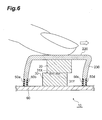
- Fig. 6 is an illustration showing an example of a state during a push on an input key in the first embodiment.
- Fig. 7 is an illustration showing an example of a state during a push on an input key in the first embodiment.
- Fig. 8 is a functional block diagram of a symbol determiner.
- Fig. 9 is a flowchart showing processing in the first embodiment.
- Fig. 10 is a decision table for making a decision on a direction of a force exerted on an input key, in the first embodiment.
- Fig. 11 is a tally table indicating an initial state in the first embodiment, and a tally table indicating a state in which a direction of a force is detected.
- Fig. 12 is an example of a symbol conversion table in the first embodiment.
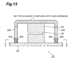
- Fig. 13 is a vertical sectional view of an input key in another example in the first embodiment.
- Fig. 14 is a vertical sectional view of an input key in another example in the first embodiment.
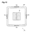
- Fig. 15 is an XV-XV sectional view of an input key shown in Fig. 14 in the first embodiment.
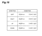
- Fig. 16 is a decision table for making a decision on a direction of a force exerted on an input key, in another example in the first embodiment.
- Fig. 17 is a vertical sectional view of an input key in the second embodiment.
- Fig. 18 is an XVIII-XVIII sectional view of an input key shown in Fig. 17 in the second embodiment.
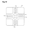
- Fig. 19 is an illustration of a configuration of a strain gage in the second embodiment.
- Fig. 20 is a decision table (first decision table) for making a decision on a direction of a force in each strain gage, in the second embodiment.
- Fig. 21 is a decision table (second decision table) for making a decision on a direction of a force exerted on an input key, in the second embodiment.
- Fig. 22 is a vertical sectional view of an input key in another example in the second embodiment.
- Fig. 23 is an XXIII-XXIII sectional view of an input key shown in Fig. 22 in the second embodiment.
- Fig. 24 is an illustration of configurations of strain gages in other examples in the second embodiment.
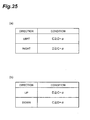
- Fig. 25 is a decision table for forces in the left and right directions in another example in the second embodiment and a decision table for forces in the up and down directions (which together constitute a first decision table).
- Fig. 26 is a decision table (second decision table) for making a decision on a direction of a force exerted on an input key, in another example in the second embodiment.
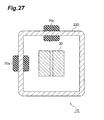
- Fig. 27 is a sectional view of an input key in another example in the second embodiment.
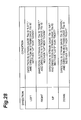
- Fig. 28 is a decision table (second decision table) for making a decision on a direction of a force exerted on an input key, in another example in the second embodiment.
- Fig. 29 is a vertical sectional view of an input key in the third embodiment.
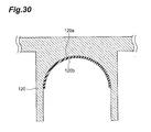
- Fig. 30 is an enlarged view of an interior portion of a key top in the third embodiment.
- Fig. 31 is a top plan view of a lower electrode located inside an input key in the third embodiment.
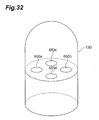
- Fig. 32 is an illustration showing a lower electrode located inside an input key in the third embodiment.
- Fig. 33 is an illustration showing a state in which a lower electrode located inside an input key is deformed in the third embodiment.
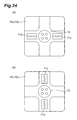
- Fig. 34 is a sectional view of an input key in another example in the third embodiment.
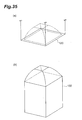
- Fig. 35 is an illustration showing an example of shape of an upper electrode and an example of shape of a lower electrode in the third embodiment.
- Fig. 36 is an example of a functional block diagram of an input apparatus in an embodiment.
- Fig. 37 is a configuration diagram of an input part of a cell phone in an example of implementing input of plural types of symbols.
- Fig. 38 is an illustration for explaining designation of symbol types assigned to an F key.
- Fig. 39 is a table showing an example of assignment of Japanese hiragana writing symbols and marks to each of keys.
- Fig. 40 is a table showing an example of assignment of English alphabet symbols and marks to each of keys.
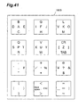
- Fig. 41 is an illustration showing a state in which alphabet letters and marks are assigned to each of keys on the basis of the assignment table of Fig. 40.
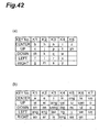
- Fig. 42 is a table showing an example of assignment of Chinese (consonants) and Chinese (vowels) to each of keys.
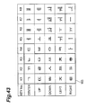
- Fig. 43 is a table showing an example of assignment of Korean symbols to each of keys.
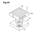
- Fig. 44 is an illustration showing a configuration example for push detection and direction detection in which a large number of strain gages are arranged in the vicinity of a surface of a key top.
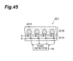
- Fig. 45 is a drawing showing a cross section along X-X line in Fig. 44 in an unpushed state and a cross section along X-X line in Fig. 44 in a pushed state.
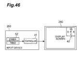
- Fig. 46 is an illustration showing a configuration example provided with a feedback function to feed up-to-date information of conversion table back to a user.
- Fig. 47 is a plan view of a key top in the fourth embodiment.
- Fig. 48 is a drawing showing a cross section along X-X line in Fig. 47 and a cross section where a strain occurs due to a force in a predetermined direction in a key top.
- Fig. 49 is a table for making a decision on a direction of a force in the fourth embodiment.
- Fig. 1 shows an exterior configuration of input apparatus 200 in the first embodiment.
- the input apparatus 200 is provided with twelve input keys 10 (generically used to refer to input keys 10a-101) of 4 vertical and 3 horizontal.
- the input apparatus 200 is used in various portable terminals such as mobile communication terminals typified by cell phones, PDAs (Personal Digital Assistants), and so on.
- Each input key 10 is assigned one or two or more symbols according to a direction or directions of force exerted on the input key 10.
- the hiragana writing symbols being one of the Japanese symbol formats will be used as an example of symbols to be inputted through the input keys 10.
- the Japanese hiragana writing symbols can be classified into a plurality of subgroups, and each subgroup consists of five symbols.
- These subgroups include the " line” group consisting of five symbols ( , , , , ) corresponding to five basic vowels, the " line” group consisting of five symbols ( , , , , ) corresponding to the foregoing five vowels coupled with a specific consonant "K”, the " line” group consisting of five symbols ( , , , , ) corresponding to the foregoing five vowels coupled with a specific consonant "S”, the " line” group consisting of five symbols ( , , , , ) corresponding to the foregoing five vowels coupled with a specific consonant "T”, and so on.
- the input key 10a is assigned a symbol group of the " line group” according to directions of force as follows: “ “ in “up”; “ “ in “right”; “ “ in “down”; “ “ in “left”; “ “ in “center”.
- indications to display the assignment are provided on the surface of the key top of the input key 10a.
- the input key 10b is assigned a symbol group of the " line group”
- the input key 10c a symbol group of the " line group”.
- the “directions” in the present embodiment will be described below with reference to Fig. 3.
- the input key 10a is placed on a support plate 60.
- a “direction” in the present embodiment indicates “up”, “down”, “left”, “right”, or “center” with respect to the plane of support plate 60.
- the “center” refers to a state in which during a push on the input key 10 no force is applied in either direction, i.e., a state in which a force vertical to the support plate 60 is exerted.
- Fig. 2 shows a functional configuration of the input apparatus 200.
- the input apparatus 200 has the input keys 10 (only the input key 10a illustrated), a push detector 36, a direction detector 38, and a symbol determiner 40.
- the push detector 36 corresponds to the push detecting means according to the present invention, the direction detector 38 to the direction detecting means according to the present invention, and the symbol determiner 40 to the information determining means according to the present invention.
- the upper part of the input key 10a (the part surrounded by a dotted line in Fig. 3) is called a key top 220a and is a portion on which a force is exerted during a push on the input key 10a.
- the push detector 36, direction detector 38, and symbol determiner 40 each may be constructed separately from the input keys 10, or may be constructed integrally therewith.
- An input key 10 is pushed when a user of the input apparatus enters a symbol. Namely, for input of a symbol in the " line group", the user exerts a force on the key top 220a of the input key 10a to push the key. When exerting the force on the key top 220a of the input key 10a, the user applies the force in one direction of "up”, “down”, “left”, “right”, or “center”, whereby a symbol can be specified.
- the push detector 36 detects a push on an input key 10.
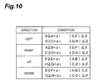
- the direction detector 38 has a decision table shown in Fig. 10 and detects a direction of a force exerted on the input key 10.
- the decision table as shown in Fig. 10, stores conditions based on strain of the input key 10 detected (conditions corresponding to directions of force exerted on the input key 10) (the details of which will be described later).
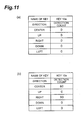
- the symbol determiner 40 has a tally table shown in Fig. 11 and a symbol conversion table shown in Fig. 12, and determines an input symbol, based on the direction detected.
- the tally table as shown in Fig. 11, stores a name of an input key 10 pushed and detection counts corresponding to the directions of force exerted on the input key 10. For example, Fig.
- the symbol conversion table stores symbols to be inputted, corresponding to an input key 10 and to the directions of force on the input key 10.
- Fig. 12 shows that " " corresponds to the center direction of the input key 10a, " “ to the up direction, " “ to the right direction, “ “ to the down direction, and " " to the left direction.
- This symbol conversion table may also be arranged so as to permit the user to freely set the corresponding symbols.
- the contents of the symbol conversion table may be arranged to be automatically updated according to statistical results of user's symbol input. For example, a symbol at a high user's input frequency may be automatically assigned to a direction or an input key 10 easier to push.
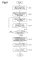
- the push detector 36, direction detector 38, and symbol determiner 40 are constructed as an integral device, as shown in Fig. 8, provided with a processor 45, a program executed by the processor 45, a memory 46 storing various tables and various data, an input interface 47 for receiving various signals, and an output interface 48 for outputting a symbol as a determination result to the outside.
- Fig. 4 shows a cross section of an input key 10.
- the input key 10 is comprised of an upper electrode 20, a lower electrode 30, a key top 220, and a key skirt 230.
- the upper electrode 20 is located so as to be stuck to the key top 220, inside the input key 10.
- the lower electrode 30 is located inside the input key 10 and on the support plate 60 and located with a clearance below the upper electrode 20.
- the upper electrode 20 is made of a conductor such as metal, and two electrically conducting pieces 31X, 31Y are embedded in a top surface of the lower electrode 30.
- the key skirt 230 is connected vertically to the support plate 60.
- a strain gage 50 (generically used to refer to strain gages 50a-50h) is attached to each of the interior side and exterior side of the key skirt 230 in the input key 10.
- the strain gages 50 to be used are, for example, those of the type making use of the resistance change due to strain of the device as described above.
- the key top 220 and the key skirt 230 are integral with each other and are made of an elastically deformable, flexible material, e.g., synthetic rubber, soft plastic, or soft vinyl. Since the key top 220 and key skirt 230 are made of such material, when a force is exerted vertically on the input key 10, the key skirt 230 is deformed as shown in Figs. 6 and 7 to bring the upper electrode 20 into contact with the lower electrode 30. When the force is eliminated, the key skirt 230 returns to the original state without contact between the upper electrode 20 and the lower electrode 30, as shown in Fig. 4, by its elastic force.
- the processing is started.
- the user pushes an input key 10 to which a symbol to be inputted is assigned, while exerting a force in a direction corresponding to the symbol to be inputted.
- the user desires to input the symbol of " "
- the user pushes the input key 10a assigned “ “”
- how to exert the force in the direction corresponding to the symbol to be inputted may be a method of exerting the force in the direction at the same time as the push, or a method of once pushing the key vertically and thereafter exerting the force in the direction while maintaining the push state.
- the upper electrode 20 goes into contact with the lower electrode 30.
- the two conducting pieces 31X, 31Y go into the conducting state through the upper electrode 20.
- the push detector 36 detects the conducting state to detect a start of the push on the input key 10 (S11).
- the symbol determiner 40 stores the name of the input key 10 in the tally table and resets the values of detection counts, i.e., turns the values of detection counts corresponding to all the directions, to "0". Since the user pushes the input key 10a herein, "key 10a" is stored in the name of the input key (S12).
- the direction detector 38 detects the direction of the force exerted on the input key 10 (S13). Specifically, the detection is carried out as follows. First, measured are resistances of the strain gages 50 attached to the key skirt 230. The resistance of each strain gage 50 decreases when compressed, or increases when stretched. Where the force is exerted in the right direction, as shown in Fig. 6, the strain gages 50a, 50c are stretched, while the strain gages 50b, 50d are compressed. This results in increasing the resistances of the strain gages 50a, 50c and decreasing the resistances of the strain gages 50b, 50d.
- a large “difference” is made between the resistances of strain gages 50 adjacent through a wall surface of the key skirt 230.
- the decision table shown in Fig. 10 shows the determination criteria and the direction detector 38 refers to the decision table to make a decision on a direction of a force exerted on the input key 10.
- a to H represent the resistances of the respective strain gages 50a-50h, and ⁇ 1 and ⁇ 2 predetermined positive values indicating the above "difference".
- ⁇ is a predetermined positive value used to determine whether there is no force applied perpendicularly to a direction in question; for example, for making a decision on a force in the left direction, it is used to determine whether there is no force applied in the directions vertical to the left direction, i.e., in the up and down directions of the input key.
- the direction detector 38 determines that "the direction of the force exerted on the input key is the right direction" if the following conditions are met as shown in Fig. 10.
- the symbol determiner 40 updates the tally table, based on the direction of the force thus determined.
- the symbol determiner 40 adds "1" to the decided direction of the force in the tally table shown in Fig. 11 (S14).
- the push detector 36 detects an end of the push on the input key 10.
- the detection of the end of the push on the input key 10 is carried out by determining whether the upper electrode 20 left the lower electrode 30 to establish a non-conducting state (S15).
- S15 a non-conducting state
- the processes of S13 to S15 are again carried out. It is preferable to make the foregoing determination on whether the non-conducting state is established, at very short time intervals on the millisecond time scale or the like.
- the symbol determiner 40 determines a direction corresponding to a maximum value of the detection counts from the tally table to which the above value was added (S16). Namely, the symbol determiner 40 determines a direction at the highest frequency of force exerted, out of the directions of force exerted on the input key 10. The direction can be deemed as a direction in which the user exerted the force with the intension. For example, where at the time of S16 the tally table is in the state shown in Fig. 11(b), the direction determined will be the right direction.
- the symbol determiner 40 determines an input symbol from the name of the key stored in the tally table and the direction thus determined, based on the symbol conversion table (S17). For example, where the name of the key stored in the tally table is "key 10a" as shown in Fig. 11 (b) and where the direction is the right direction, the symbol determiner 40 determines that the input symbol is " ", based on the symbol conversion table corresponding to the key 10a as shown in Fig. 12. Then the symbol determiner 40 outputs the symbol thus determined (S18).
- the input key 10 of the present embodiment is able to detect a push on the input key 10 and to detect a direction of a force exerted on the input key 10, without need for a plurality of additional pressure sensors. Therefore, it becomes feasible to specify an information item (an information item to be inputted by the user) according to the direction of the force detected, and to enter an information item.
- the input apparatus 200 of the present embodiment is able to detect a direction of a force exerted on the input key 10 and to enter an information item according to the direction, without provision of additional pressure sensors or the like. It is thus feasible to realize the input key or the input apparatus superior in cost and in readiness of implementation.
- the key top 220 itself was made of the elastically deformable, flexible material, but the part of the key top 220 may also be made of a material with some hardness, as shown in Fig. 13.
- the material with some hardness is preferably, for example, hard plastic, metal, or the like.
- the above configuration eliminates an uncomfortable feel due to a dent of the key top part during a push on the input key 10, permits the user to more clearly sense a touch of movement in the up, down, left, and right directions through deformation of only the peripheral part, and thus presents a favorable touch for the user.
- the strain gages 50 were attached to the exterior surface and to the interior surface of the key skirt 230 in each direction, but the strain gages 50 may be attached only to the exterior surface of the key skirt 230, as shown in Figs. 14 and 15.
- the decision on the direction of leftward or rightward force can be made by use of resistances of the strain gages 50 attached to the left and right exterior surfaces of the key skirt 230 in each direction, based on the decision table shown in Fig. 16.
- ⁇ in Fig. 16 is a predetermined positive value indicating a difference, as in the above.
- the strain gages 50 may also be attached only to the interior surface, instead of the exterior surface of the key skirt 230. In that case, the condition for the left direction and the condition for the right direction in the decision table are reversed, and the condition for the up direction and the condition for the down direction are reversed.
- the push detector 36 and the direction detector 38 are constructed separately from the input key 10, but they may also be constructed integrally with the input key 10 as shown in Fig. 36.
- the above embodiment showed the input example of the Japanese hiragana writing symbols with Fig. 1, and in practice Japanese input requires input of several types of symbols including the katakana writing symbols, numerals, and alphabet, in addition to the hiragana writing symbols.
- the following will describe an example of input of several types of symbols, using an extra key (hereinafter referred to as a "symbol type designation key") provided for designating a type of a symbol to be inputted.
- an input portion 160 of a cell phone is composed of a special key arrangement part 160A and a symbol input key arrangement part 160B, wherein the symbol input key arrangement part 160B includes twelve (three horizontal x four vertical) keys 161 and wherein the special key arrangement part 160A includes a symbol type designation key (hereinafter abbreviated as an "F key") 162.
- the symbol input key arrangement part 160B includes twelve (three horizontal x four vertical) keys 161 and wherein the special key arrangement part 160A includes a symbol type designation key (hereinafter abbreviated as an "F key") 162.
- the F key 162 is assigned symbol type designations for respective moving directions as follows.
- the F key 162 is so arranged that symbol types tending to be frequently inputted can be designated by one operation (a movement of a finger), for example, center (still)-hiragana writing symbols, upward-half-width (one byte) numbers, leftward-half-width English lower-case symbols, downward-half-width katakana writing symbols, and rightward-half-width English upper-case symbols.
- the F key 162 is so configured that the symbol types other than the above can be designated by two operations. Namely, as shown in the space outside the frame of the F key 162 in Fig.
- the symbol type of full-width (two bytes) numbers can be designated by two continuous upward movements of a finger, and the symbol type of full-width English lower-case symbols by two continuous leftward movements of a finger.
- the symbol type of full-width katakana writing symbols can be designated by two continuous downward movements of a finger, and the symbol type of full-width English upper-case symbols by two continuous rightward movements of a finger. In this manner two continuous movements of a finger in a specific direction enable designation of a symbol type different from that designated by only one movement of a finger in that specific direction, thus providing expandability about designation of symbol types.
- the symbol assignment to the twelve keys 161 in the symbol input key arrangement part 160B is, for example in the case of the hiragana writing symbols, that as shown in Fig. 39. Since the hiragana writing symbols can be classified under the symbol groups each consisting of five symbols like "five symbols in the line group", "five symbols in the line group”..., as described previously, one symbol group (five symbols) can be assigned to one key 161. As shown in the table format of Fig. 39, the key K1 is assigned the "five symbols ( , , , , ) in the line group", and the key K2 the "five symbols ( , , , , ) in the line group". In this manner, one symbol group (five symbols) can be assigned to one key 161.
- the special symbols among the hiragana writing symbols include an example of display of symbols in size smaller than usual (e.g., " “, “ “, etc.), an example of display of voiced consonants (e.g., “ “, “ “, etc.), and an example of display of p-sounds (e. g., " ", “ “, etc.) .
- the hiragana writing symbols are often converted into katakana small symbols or katakana large symbols. Therefore, as shown in the assignment to the key K12 in the table of Fig.
- the present invention which facilitates the input operation by assigning a plurality of symbols, marks, or functions to one key as shown in Fig. 39 and decreasing the number of key input operations, can also be applied to input of symbols in the other languages. Examples of application of the present invention to input of English, German, French, Chinese, and Korean symbols will be described below.
- the English symbols include twenty six symbols in total, and are not grouped into symbol groups each consisting of five symbols, different from the Japanese hiragana writing symbols.
- a conceivable method is to assign five symbols to each key in order from the top of the alphabet (A, B, C,...), as shown in Fig. 40.
- the keys K1-K6 are enough to assign all the twenty six symbols, and many keys are still left. Therefore, many marks (e.g., return (CR), tab (TAB),...) can be assigned to the remaining keys.
- the assignment table of Fig. 40 shows the assignment of the alphabet and marks to the keys (K1-K12), and
- Fig. 41 shows an example of actual assignment to each of the keys (K1-K12) in the symbol input key arrangement part 160B (cf. Fig. 37), based on the assignment table.
- a switchover among four symbol types of half-width English lower-case symbols, full-width English lower-case symbols, half-width English upper-case symbols, and full-width English upper-case symbols can be implemented by manipulating the F key 162 in Fig. 37.
- Fig. 38 shows the F key 162 in Japanese, and, since the English does not include the hiragana and katakana writing symbols, all the four symbol types can be assigned to the four directions of the F key 162 in Fig. 37, whereby one can designate a desired English symbol type by one operation on the F key 162.
- the peculiar symbols as described above can replace the mark-assigned portions in the assignment table of Fig. 40, whereby the input of the symbol types equivalent to those through the full keyboard can be implemented by one operation (a movement of a finger).
- the function equivalent to that of the full keyboard can be substantialized by the smaller number of input keys, and the input of symbols can be implemented by the reduced number of input operations, thus dramatically improving the efficiency of input operation.
- the peculiar symbols are é (accent aigu), à, è, ù (accent grave), â, i, û, ê, ô (accent circonflexe), i, ü, ⁇ (tréma), ç (cédille), oe (o e legal), and so on.
- a common Chinese symbol input method is the pin-yin input system of inputting an alphabet sequence (pin-yin) equivalent to the reading (pronunciation) of a symbol as an input object.
- This pin-yin input system is classified under two input methods of complete pin input and bi-pin input.
- the complete pin input uses the English keyboard as it is, and pin-yin is inputted in each symbol unit according to the alphabetical notation on the keyboard. For example, where Chinese “ “ corresponding to “ (sunny today) " is inputted, an alphabet sequence "JIN” corresponding to the reading (pronunciation) of “ “, an alphabet sequence “TIAN” corresponding to the reading (pronunciation) of “ “, and an alphabet sequence "QING” corresponding to the reading (pronunciation) of " " are inputted in order according to the alphabet notation on the English keyboard. Therefore, the key assignment as shown in Fig. 40 and Fig.
- the bi-pin input is a way of inputting each symbol by separate use of Chinese (head consonant) and (subsequent vowel component).
- the " " means a consonant at the head of a syllable, and " " means a portion except for the head consonant in the syllable, the " " " always containing a vowel.
- symbols are inputted by switching in an order of (consonant) ⁇ (vowel component) ⁇ (consonant) ⁇ (vowel component) .
- this input method involves a device of reducing the number of typing operations on the keyboard by the separate use of and , and, once one learns the keyboard arrangement of the bi-pin input, he or she can input symbols by the smaller number of input operations than by the aforementioned complete pin input, so as to realize efficient symbol input.
- the bi-pin input of this type requires two key assignments, (head consonant) key assignment for input of and (subsequent vowel component) key assignment for input of .
- the present invention can be applied to these key assignment and key assignment.
- Fig. 42(a) shows an example of the key assignment.
- the key K1 is assigned five (consonants) (b, c, ch, f, g), and which consonant was inputted can be determined by a moving direction of a finger on the key K1.
- the keys K2-K5 can also be assigned consonants in similar fashion.
- Fig. 42(b) shows an example of the key assignment.
- the key K1 is assigned five (vowel components) (a, ai, an, ang, ao), and which vowel component was inputted can be determined by a moving direction of a finger on the key K1.
- the keys K2-K7 can also be assigned vowel components in similar fashion.
- the consonant and vowel component key assignments as shown in Fig. 42 enable one to input the symbol types equivalent to those through the full keyboard by one operation (a movement of a finger). Namely, the function equivalent to that of the full keyboard can be substantialized by the smaller number of input keys, and the symbol input can be implemented by the reduced number of input operations, thereby dramatically improving the efficiency of input operation.
- the marks e.g., !, ?, etc.
- the various types of marks are also often inputted. It is thus desirable to assign the various types of marks to the remaining portions in the key assignments of Fig. 42, just as in the case of the assignment example of the English symbols in Fig. 40, thereby achieving efficient input as to input of marks as well.
- Each Korean symbol (hangul symbol) is composed of a combination of a consonant with a vowel. Therefore, for symbol input, it is necessary to input a consonant-indicating part and a vowel-indicating part for each symbol.
- An example of this assignment is presented in Fig. 43.
- portions surrounded by thick line 163 represent the nineteen portions indicating the consonants, and the other twenty one portions correspond to the portions indicating the vowels.
- the keys can be assigned the forty portions indicating the respective sounds, the forty sounds in total including the nineteen consonants and twenty one vowels, as described above, it becomes feasible to input the symbol types equivalent to those through the full keyboard by one operation (a movement of a finger). Namely, the function equivalent to that of the full keyboard can be substantialized by the smaller number of input keys, and the symbol input can be implemented by the reduced number of input operations, thereby dramatically improving the efficiency of input operation.
- the marks e.g., !, ?, etc.
- the remaining keys keys K9-K12
- the present invention is applicable to input of symbols in various languages, and achieves the excellent effects of substantializing the function equivalent to that of the full keyboard by the smaller number of input keys and enabling the symbol input by the reduced number of input operations, thereby dramatically improving the efficiency of input operation.
- Fig. 17 shows a cross section of an input key 10 in the second embodiment.
- Fig. 18 shows an XVIII-XVIII cross section of the input key 10 shown in Fig. 17.
- the exterior configuration and functional configuration of input apparatus 200 are similar to those in the first embodiment.
- strain gages 70 are attached to a connection of the support plate 60 to the input key 10, i.e., to the lower part of the key skirt 230.
- the other structure of the input key 10 is similar to that in the first embodiment. Since in the above configuration a force exerted on the input key 10 is transferred to the strain gages 70, a direction of the force exerted can be determined by measuring resistances of the strain gages 70.
- Each strain gage 70 used in the present embodiment is comprised of four strain gage pieces 71 (generically used to refer to strain gage pieces 71a-71d) provided in the directions of up, down, left, and right, and a key skirt mount portion 72, as shown in Fig. 19.
- the direction detector 38 measures resistances of these four strain gage pieces 71 and thus can decompose a force exerted, into vertical and horizontal components and detect the vertical and horizontal components.
- the processing executed in the input apparatus 200 of the present embodiment is much the same as that described in the above first embodiment except for the detection of the direction of the force exerted on the input key 10 (S13 in Fig. 9). The process of detection of the direction will be described below.
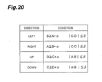
- the direction detector 38 determines a direction of force in each strain gage 70 in a manner similar to the aforementioned direction on the direction, using the first decision table shown in Fig. 20.
- a to D in the above decision table represent resistances of the respective strain gage pieces 70a-70d
- ⁇ a predetermined positive value indicating the above "difference”.
- ⁇ is a predetermined positive value used to determine whether there is no force applied perpendicularly to a direction in question; for example, for making a decision on a force in the left direction, it is used to determine whether there is no force applied in the directions vertical to the left direction, i.e., in the up and down directions.
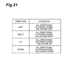
- a direction is made on the direction of the force exerted on the input key 10 with reference to the second decision table shown in Fig. 21, based on directions of force in the respective strain gages 70 obtained as described above. Specifically, for example, where a force is exerted in the right direction on the input key 10 to push the input key 10, the direction is determined to be right in all the above strain gages 70, and it is determined that the direction of the force exerted on the input key 10 is the right direction, based on the directions thus determined and based on the second decision table.
- the input apparatus 200 of the present embodiment obviates the need for attaching the strain gages to the input key 10 itself, and thus can prevent increase of weight of the input key 10 and prevent the key touch from becoming weighty.
- the input key 10 itself can be one of the conventional keys.
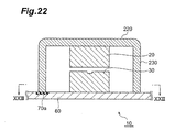
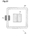
- each strain gage 70 is able to detect the up, down, left, and right directions of force, it is also possible to use only one strain gage 70a, as shown in Figs. 22 and 23.
- the above implements a simpler configuration of input key 10 and thus achieves reduction of cost.
- each strain gage 70 consists of four strain gage pieces 71 and is arranged to be able to detect the up, down, left, and right directions of force.
- the apparatus may be configured so that, as shown in Fig. 24(a), each strain gage 70 includes two strain gage pieces 71 so as to be able to detect only the left and right directions of force, using the first decision table shown in Fig. 25(a), and that a direction is made on a direction of a force exerted on the input key 10, based on directions of force in the respective gages 70 and based on the second decision table shown in Fig. 26.
- the apparatus may also be configured so that, as shown in Fig.
- each strain gage 70 includes two strain gage pieces 71 so as to be able to detect only the up and down directions of force, using the first decision table shown in Fig. 25(b), and that a decision is made on a direction of a force exerted on the input key 10, based on the directions of force in the respective gages 70 and based on the second decision table shown in Fig. 26.
- the number of strain gages 70 may be two as shown in Fig. 27 and the second decision table shown in Fig. 28 may be used for the decision on the direction. The above implements a simpler configuration of the input key 10 and achieves further reduction of cost.
- Fig. 29 shows a cross section of an input key 10 in the third embodiment.
- the exterior configuration and functional configuration of input apparatus 200 are similar to those in the first embodiment.
- the input key 10 is comprised of an upper electrode 120, a lower electrode 130, a key top 420, a key skirt 430, and a spring 500.
- the key top 420 and key skirt 430 are integral with each other and are made of a material with some hardness, e.g., hard plastic, metal, or the like.
- a key skirt edge 430a engages with a support plate flange 60a of support plate 60, whereby the key top 420 is prevented from slipping off from the support plate 60.
- the upper electrode 120 is made of a material similar to that of the key top 420 and in cylindrical shape, and is located so as to be stuck to the key top 420 inside the input key 10.
- the lower part of the upper electrode 120 is of a round concave shape and is loosely engageable with the lower electrode 130 having the upper part of a round convex shape.
- a concave surface portion 120a of the upper electrode 120 is provided with an electric contact 120b of a metal piece over the entire surface.
- the lower electrode 130 is provided on the support plate 60 inside the input key 10 and is located with a clearance below the upper electrode 120.
- the lower electrode 130 is cylindrical and the upper part thereof is of the round convex shape.
- thousands of electric contacts 130a, 130b are provided on the upper part of the convex shape of the lower electrode 130.
- the electric contacts consist of those of white dots 130a and those of black dots 130b, and these electric contacts 130a, 130b go into an electrically conducting state when the upper electrode 120 is brought into contact with the lower electrode 130 to establish contact of the electric contact 120b of the upper electrode with the electric contacts 130a, 130b.
- the push detector 36 detects the conducting state to detect a push on the input key 10.
- the lower electrode 130 is made of an elastically deformable, flexible material, and is provided with strain gages 650 (generically used to refer to strain gages 650a-650d) inside thereof, as shown in Fig. 32.
- the spring 500 is provided so as to surround the upper electrode 120 and lower electrode 130 of cylindrical shape, one end of the spring vertically pushes up the key top 420, and the other end vertically pushes down the support plate 60.
- a normal state a state without force on the input key 10
- the key top 420 is at a stop at a position where the key skirt edge 430a is in contact with the support plate flange 60a.
- the processing executed in the input apparatus 200 of the present embodiment is much the same as that described in the first embodiment except for the detection of a push on the input key 10 and the detection of the direction of force (S11 and S13 in Fig. 9). The processes of the detection of the push and the detection of the direction will be described below.
- the spring 500 is compressed to bring the upper electrode 120 into contact with the lower electrode 130 to establish the conducting state, and the push detector 36 detects the push on the input key 10 (corresponding to S11 in Fig. 9).
- the force applied in the direction corresponding to the symbol to be inputted is transmitted through the concave shape portion of the upper electrode 120 to the lower electrode 130, whereby there arises strain in the direction corresponding to the symbol to be inputted, in the lower electrode 130.
- the strain arising in the lower electrode 130 deforms the strain gages 650 provided inside the lower electrode 130, and, based on change of resistances of the strain gages 650 due to the strain, the direction detector 38 detects the direction of the force exerted on the input key 10 in a manner similar to that in the above embodiment (corresponding to S13 in Fig. 9).
- the input apparatus 200 of the present embodiment uses the spring in the input key 10, which can improve the click feel when the user pushes the input key 10.
- the piston 120c and the embossed sheet 120d similarly descend until the upper electrode 120 and the lower electrode 130 go into contact.
- the piston 120c and the embossed sheet 120d go into contact with each other.
- the embossed sheet 120d gives a reaction force.
- the force applied exceeds the given level, the embossed sheet 120d gets dented at a breath, so as to instantaneously decrease the reaction.
- the user can sense the decrease of reaction at the fingertip.
- the embossed sheet 120d gradually returns from the dented state of the center bulging portion to the original shape, so as to elevate the input key 10.
- the center bulging portion returns up to a certain shape, it suddenly generates a strong restoring force to quickly strengthen the force to lift the input key 10.
- the above permits the user of the input apparatus 200 to further obtain a touch of a push on the key top 420, so called a "click feel", when pushing the input key 10 provided in the input apparatus 200.
- a click feel when pushing the input key 10 provided in the input apparatus 200.
- it provides the user with a light keying feel.
- the upper electrode 120 and lower electrode 130 are of cylindrical shape, but they may also be of rectangular column shape, as shown in Fig. 35 (a) and (b).
- This configuration is particularly preferable, for example, in cases where the direction of force to be applied is limited to the four directions of up, down, left, and right.
- contact surfaces are preferably curved surfaces, in order to secure the contact surfaces as wide as possible.
- Fig. 45 shows a sectional view along X-X line in Fig. 44 (input key configuration example).
- a layer of an elastically deformable, flexible material e.g., synthetic rubber, soft plastic, soft vinyl, or the like
- strain gages 221C are embedded in two-dimensional arrangement along the direction along X-X line in Fig. 44 and along the direction perpendicular thereto and over the entire surface of the sensor part 221, in the layer of flexible material 221B.
- the strain gages 221C have a property that at occurrence of strain under pressure their electrical resistance demonstrates a predetermined change according to an amount of the strain.
- Output terminals of each strain gage 221C are electrically connected to two electric wiring lines A, B, and a given potential difference is established between these electric wiring lines A, B by an unrepresented dc power supply or the like. For this reason, when a strain occurs in a certain strain gage 221C under pressure, the electrical resistance of the strain gage 221C demonstrates a predetermined change according to an amount of the strain, and the value of an electric current flowing in the strain gage 221C varies according to the strain amount.
- the value of the electric current flowing in each strain gage 221C is detected by an unrepresented electric current detector and the electric current value information is fed to the push detector 36.
- the push detector 36 receives the electric current value information, the push detector 36 first detects which strain gage 221C is subject to pressure over a reference value, based on the current value information of each strain gage 221C, to detect a push on the key top 220.
- the push detector 36 When the push detector 36 detects the push, it continuously outputs the information of the values of electric currents flowing in the respective strain gages 221C, to the direction detector 38 for a predetermined period, and the direction detector 38 measures a distribution of pressures at respective points from the strain gages 221C, calculates a center of gravity of the pressure distribution (center), and detects the direction of the push on the key top 220, based on the position of the center of gravity or based on a direction of a change of the center of gravity over the predetermined period. Then the information about the direction of the push on the key top 220 detected by the direction detector 38 is fed to the symbol determiner 40, and the symbol determiner 40 can determine the symbol information corresponding to the direction of the push.
- the fourth embodiment will be described below as an embodiment adopting a mechanism of detecting strain caused by force in the up, down, left, and right directions on the key top, in the upper part of the key top or in the peripheral part of the surface of the key top.
- Fig. 47 is a plan view of a key top 80 in the fourth embodiment, and the key top 80 is made of an elastically deformable material.
- Strain gages 81A-81D for detecting strain caused by force in the up, down, left, and right directions in Fig. 47 are embedded in this key top 80 (each strain gage is indicated by solid lines in Fig. 47, for convenience' sake).
- each strain gage is indicated by solid lines in Fig. 47, for convenience' sake.
- those 81A, 81B detect strain caused by force in the up and down directions in Fig. 47
- those 81C, 81D detect strain caused by force in the left and right directions in Fig. 47.
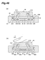
- Fig. 48(a) shows a cross-sectional view along X-X line in Fig. 47.
- the strain gages 81C, 81D are embedded with opposite inclinations (e.g., 45° with respect to the surface of the key top 80) in the key top 80, in order to distinctively detect the strain due to force in the left direction and the strain due to force in the right direction in Fig. 47 and Fig. 48(a).
- the key top 80 is deformed in the left direction in Figs.
- the strain gage 81C is subject to pressure in the compressing direction of the strain gage 81C, while the strain gage 81D is subject to pressure in the stretching direction of the strain gage 81D. This direction decision method will be described later.
- the key top 80 is set on a key top base 82, and the key top base 82 is arranged in an aperture provided in a top surface of substrate 83.
- Key top skirts 82A, 82B projecting outward inside the aperture in the top surface of the substrate 83 are formed at the bottom edge of the key top base 82, so as to prevent the key top base 82 and the key top 80 from slipping off from the substrate 83.
- Key top supports 90 made of an elastically deformable material (e.g., synthetic rubber, a spring, or the like) connect between the key top skirt 82A and an opposed surface 83A of the substrate 83 and between the key top skirt. 82B and an opposed surface 83B of the substrate 83.
- the key top base 82 including the key top skirts 82A, 82B is made of a material with some hardness, and this prevents the key top base 82 and the key top 80 from slipping off from the substrate 83 and facilitates deformation of only the key top 80 of the elastic material in which the four strain gages are embedded.
- an upper electrode 84 is set in the central region of the bottom surface, strain-gage upper electrodes 88A, 88B are set in the vicinity of the embedded part of the strain gage 81C, and strain-gage upper electrodes 86A, 86B are set in the vicinity of the embedded part of the strain gage 81D. Ends of the strain gage 81C are electrically connected to the respective strain-gage upper electrodes 88A, 88B, and ends of the strain gage 81D are electrically connected to the respective strain-gage upper electrodes 86A, 86B.
- a lower electrode 85, and strain-gage lower electrodes 89A, 89B, 87A, and 87B are set at the positions corresponding to the upper electrode 84 and the strain-gage upper electrodes 88A, 88B, 86A, and 86B, respectively, on an opposed surface of the substrate 83 to the key top base 82.
- the resistance of each strain gage 81A-81D decreases when the strain gage is compressed, and increases when the strain gage is stretched.
- a cross section along Y-Y line in Fig. 47 shows much the same configuration as the X-X cross section of Fig. 48(a) described above, and the description thereof is omitted herein.
- the functional configuration of the input apparatus in the fourth embodiment is similar to the configuration of the input apparatus 200 in Fig. 2 described above, and the illustration thereof is omitted herein.
- electric signals from the respective strain-gage lower electrodes 89A, 89B, 87A, and 87B are fed to the direction detector 38, and the direction detector 38 detects the strain caused by force in the up, down, left, and right directions exerted on the key top 80, to make a decision on the direction of the force exerted on the input key.
- the upper electrode 84 becomes electrically connected to the lower electrode 85 and, similarly, the strain-gage upper electrodes 88A, 88B, 86A, and 86B become electrically connected to the opposed strain-gage lower electrodes 89A, 89B, 87A, and 87B, respectively.
- the direction detector 38 determines the resistances of the strain gages 81A, 81B, and 81D.
- strain gage 81D is stretched while the strain gage 81C is compressed.
- the strain gages 81A, 81B undergo little compression or expansion.
- resistance D increases the resistance of the strain gage 81D (hereinafter referred to as “resistance D"), decreasing the resistance of the strain gage 81C (hereinafter referred to as “resistance C”), and hardly changing the resistance of the strain gage 81A (hereinafter referred to as “resistance A”) and the resistance of the strain gage 81B (hereinafter referred to as “resistance B”).
- the resistance D becomes a predetermined value or more larger than the resistance C, and the difference between the resistances A, B is close to 0.
- the conditions that the resistance D is not less than (resistance C + predetermined positive value ⁇ ) and that the difference between the resistances A, B is not more than the predetermined positive value ⁇ are met, as shown in Fig. 49, whereby the direction detector 38 determines that the strain due to the force in the left direction in Fig. 47 occurs in the key top 80, and thus makes a decision based thereon that the direction of the force exerted on the input key is the left direction in Fig. 47.
- the strain gage 81C is stretched while the strain gage 81D is compressed.
- the strain gages 81A, 81B undergo little compression or expansion. This results in increasing the resistance C, decreasing the resistance D, and hardly changing the resistances A, B. Namely, the resistance C becomes a predetermined value or more larger than the resistance D, and the difference between the resistances A, B is close to 0.
- the conditions that the resistance C is not less than (resistance D + predetermined positive value ⁇ ) and that the difference between the resistances A, B is not more than the predetermined positive value ⁇ are met, as shown in Fig. 49, whereby the direction detector 38 determines that the strain due to the force in the right direction in Fig. 47 occurs in the key top 80 and thus makes a decision based thereon that the direction of the force exerted on the input key is the right direction in Fig. 47.
- the detection is also carried out in similar fashion in cases where the strain due to force in the up direction or in the down direction in Fig. 47 occurs in the key top 80.
- the present embodiment provides the significant advantage in capability of distinctively detecting the strains due to the force in each of the up, down, left, and right directions in Figs. 47 and 48(a) thanks to the configuration wherein the strain gages 81C, 81D are embedded with mutually opposite inclinations in the key top 80 and wherein the strain gages 81A, 81B are embedded with mutually opposite inclinations in the key top 80.
- each of the above embodiments is preferably configured to be able to feed the up-to-date information of the conversion tables about the input keys back to the user during the push operation on the input key by the user.
- a configuration with such feedback function of the up-to-date information of conversion tables to the user will be described below.
- the input apparatus 200 is further provided with a controller 41, and during a push operation on an input key (i.e., during a period from a start of the operation on the key top to confirmation of operation settlement by a switch) the controller 41 outputs to the display screen 280 information of the conversion table 52 about the input key at that time (information assigned to each direction) to highlight the input candidate information corresponding to the push operation at the present time on the display screen 280.
- the controller 41 outputs to the display screen 280 information of the conversion table 52 about the input key at that time (information assigned to each direction) to highlight the input candidate information corresponding to the push operation at the present time on the display screen 280.
- the feedback is desirably carried out, for example, at a time of a change in assignment of plural input information elements to the input keys according to frequencies of use or the like, or at timing immediately after manipulation of the F key 162 in Fig. 37 (i.e., immediately after a mode changeover of symbol input) even without any change in assignment, and this achieves the three effects below.
- the user can check the up-to-date assignment information of the different input mode, which is not easily indicated by only the display on the key top, in the image 42. Furthermore, (3) the user can also check in the image 42 the information as an input candidate corresponding to a push operation at that moment (information selected at the present time). This feedback function of the up-to-date assignment information can dramatically improve easiness and certainty of the user operation.
Landscapes
- Engineering & Computer Science (AREA)
- General Engineering & Computer Science (AREA)
- Theoretical Computer Science (AREA)
- Human Computer Interaction (AREA)
- Physics & Mathematics (AREA)
- General Physics & Mathematics (AREA)
- Input From Keyboards Or The Like (AREA)
- Push-Button Switches (AREA)
Applications Claiming Priority (4)
| Application Number | Priority Date | Filing Date | Title |
|---|---|---|---|
| JP2003406230 | 2003-12-04 | ||
| JP2003406230 | 2003-12-04 | ||
| JP2004292915A JP2005190460A (ja) | 2003-12-04 | 2004-10-05 | 入力キー及び入力装置 |
| JP2004292915 | 2004-10-05 |
Publications (2)
| Publication Number | Publication Date |
|---|---|
| EP1538648A2 true EP1538648A2 (de) | 2005-06-08 |
| EP1538648A3 EP1538648A3 (de) | 2007-12-12 |
Family
ID=34467855
Family Applications (1)
| Application Number | Title | Priority Date | Filing Date |
|---|---|---|---|
| EP04027773A Withdrawn EP1538648A3 (de) | 2003-12-04 | 2004-11-23 | Eingabetaste und Eingabegerät. |
Country Status (6)
| Country | Link |
|---|---|
| US (1) | US7271361B2 (de) |
| EP (1) | EP1538648A3 (de) |
| JP (1) | JP2005190460A (de) |
| KR (1) | KR100685158B1 (de) |
| CN (1) | CN1296803C (de) |
| TW (1) | TWI283822B (de) |
Cited By (2)
| Publication number | Priority date | Publication date | Assignee | Title |
|---|---|---|---|---|
| WO2006135338A1 (en) * | 2005-06-15 | 2006-12-21 | Innomedia Pte Ltd | Keypad input device |
| CN113130243A (zh) * | 2021-04-02 | 2021-07-16 | 枣庄三人行通讯有限公司 | 一种可以调节的机械键盘轴体 |
Families Citing this family (35)
| Publication number | Priority date | Publication date | Assignee | Title |
|---|---|---|---|---|
| DE10204379B4 (de) * | 2002-02-02 | 2008-06-26 | Völckers, Oliver | Einrichtung zur Texteingabe durch eine Betätigung von Tasten eines nummerischen Tastenblocks für elektronische Geräte und Verfahren zur Verarbeitung von Eingabeimpulsen bei einer Texteingabe |
| US7310053B2 (en) | 2003-04-24 | 2007-12-18 | Taylor Bollman | Compressed standardized keyboard |
| US20040222979A1 (en) * | 2003-05-08 | 2004-11-11 | Knighton Mark S. | Multifunction floating button |
| US8734036B2 (en) * | 2003-08-29 | 2014-05-27 | Steven B. Hirsch | Keyboard and keys |
| US9575567B2 (en) * | 2003-08-29 | 2017-02-21 | Steven B. Hirsch | Keyboard and keys |
| US7131780B2 (en) * | 2003-08-29 | 2006-11-07 | Hirsch Steven B | Keyboard |
| US20100040400A1 (en) * | 2003-08-29 | 2010-02-18 | Hirsch Steven B | Keyboard and keys |
| US7953448B2 (en) * | 2006-05-31 | 2011-05-31 | Research In Motion Limited | Keyboard for mobile device |
| KR101137836B1 (ko) * | 2005-07-22 | 2012-04-18 | 엘지전자 주식회사 | 다목적 사이드키를 갖는 이동단말기 |
| JP4682733B2 (ja) * | 2005-07-28 | 2011-05-11 | 富士通株式会社 | キーボード検査装置、およびキーボード検査方法 |
| US20070137901A1 (en) * | 2005-12-16 | 2007-06-21 | E-Lead Electronic Co., Ltd. | Micro-keyboard simulator |
| US20070236368A1 (en) * | 2006-03-17 | 2007-10-11 | E-Lead Electronic Co., Ltd. | Miniaturized keyboard |
| US7646315B2 (en) * | 2006-06-08 | 2010-01-12 | Motorola, Inc. | Method and apparatus for keypad manipulation |
| CN101286424B (zh) * | 2007-04-11 | 2012-01-25 | 深圳富泰宏精密工业有限公司 | 键盘组件 |
| WO2009008686A2 (en) * | 2007-07-11 | 2009-01-15 | Eui Jin Oh | Data input device by detecting finger's moving and the input process thereof |
| CN101430605B (zh) * | 2007-11-07 | 2010-12-08 | 宏达国际电子股份有限公司 | 字符输入方法 |
| US8993913B2 (en) * | 2011-06-02 | 2015-03-31 | Universal Cement Corporation | Cover glass pressure button |
| US9477320B2 (en) * | 2011-08-16 | 2016-10-25 | Argotext, Inc. | Input device |
| TWI473134B (zh) * | 2011-11-17 | 2015-02-11 | Darfon Electronics Corp | 按鍵 |
| US9343247B2 (en) | 2011-11-17 | 2016-05-17 | Darfon Electronics Corp. | Keyswitch |
| US8896539B2 (en) | 2012-02-03 | 2014-11-25 | Synerdyne Corporation | Touch-type keyboard with character selection through finger location on multifunction keys |
| US8414207B1 (en) | 2012-02-03 | 2013-04-09 | Synerdyne Corporation | Ultra-compact mobile touch-type keyboard |
| US8686948B2 (en) | 2012-02-03 | 2014-04-01 | Synerdyne Corporation | Highly mobile keyboard in separable components |
| US8629362B1 (en) | 2012-07-11 | 2014-01-14 | Synerdyne Corporation | Keyswitch using magnetic force |
| CN103580666B (zh) * | 2012-08-07 | 2016-08-24 | 环球水泥股份有限公司 | 电子装置的保护玻璃压力传感器按键 |
| US20140071654A1 (en) | 2012-09-11 | 2014-03-13 | Logitech Europe S.A. | Protective Cover for a Tablet Computer |
| US20140104174A1 (en) * | 2012-10-17 | 2014-04-17 | International Business Machines Corporation | Ultra-Compact Keyboard |
| US20140104179A1 (en) * | 2012-10-17 | 2014-04-17 | International Business Machines Corporation | Keyboard Modification to Increase Typing Speed by Gesturing Next Character |
| US8766125B2 (en) * | 2012-11-09 | 2014-07-01 | Universal Cement Corporation | Pressure key |
| US9235270B2 (en) | 2013-02-26 | 2016-01-12 | Synerdyne Corporation | Multi-touch mechanical-capacitive hybrid keyboard |
| CN106774971A (zh) * | 2015-11-24 | 2017-05-31 | 西安中兴新软件有限责任公司 | 一种字符输入方法及装置 |
| CN105589029A (zh) * | 2016-03-14 | 2016-05-18 | 苏州工业职业技术学院 | Pcb在线测试装置与测试方法 |
| US10394342B2 (en) * | 2017-09-27 | 2019-08-27 | Facebook Technologies, Llc | Apparatuses, systems, and methods for representing user interactions with real-world input devices in a virtual space |
| JP7133133B2 (ja) * | 2019-04-23 | 2022-09-08 | トヨタ自動車株式会社 | スイッチ装置 |
| EP4645699A3 (de) * | 2023-08-23 | 2026-01-07 | HUF Hülsbeck & Fürst GmbH & Co. KG | Vorrichtung zur erfassung von betätigungsvorgängen an kraftfahrzeugen |
Citations (4)
| Publication number | Priority date | Publication date | Assignee | Title |
|---|---|---|---|---|
| CA1274602A (en) | 1987-05-29 | 1990-09-25 | Samsen Rohm | Character input/output device |
| JPH09230999A (ja) * | 1996-02-26 | 1997-09-05 | Oki Inf Syst | ポインティングデバイス |
| US6040821A (en) | 1989-09-26 | 2000-03-21 | Incontrol Solutions, Inc. | Cursor tracking |
| EP1193643A1 (de) * | 2000-09-28 | 2002-04-03 | Nokia Corporation | Steuervorrichtung |
Family Cites Families (21)
| Publication number | Priority date | Publication date | Assignee | Title |
|---|---|---|---|---|
| US5528235A (en) * | 1991-09-03 | 1996-06-18 | Edward D. Lin | Multi-status multi-function data processing key and key array |
| JPH067127U (ja) * | 1992-06-29 | 1994-01-28 | ミツミ電機株式会社 | 押しボタンスイッチ |
| JPH08202493A (ja) * | 1995-01-23 | 1996-08-09 | Tokin Corp | ポインティング装置 |
| JPH0937358A (ja) * | 1995-07-20 | 1997-02-07 | Sony Corp | キーボードとビデオカメラ制御システム |
| JPH09222948A (ja) | 1996-02-19 | 1997-08-26 | Fujitsu Takamisawa Component Kk | ポインティングデバイスとその製造方法 |
| US6201468B1 (en) * | 1997-10-14 | 2001-03-13 | Devolpi Dean R. | Deflection sensor |
| US5912612A (en) * | 1997-10-14 | 1999-06-15 | Devolpi; Dean R. | Multi-speed multi-direction analog pointing device |
| JPH11237945A (ja) | 1998-02-20 | 1999-08-31 | Nec Shizuoka Ltd | キーボード用のキー |
| JP2000089896A (ja) * | 1998-09-08 | 2000-03-31 | Toshiba Corp | コード入力装置 |
| JP3671116B2 (ja) * | 1998-09-29 | 2005-07-13 | ホシデン株式会社 | 多方向入力装置 |
| JP2000156133A (ja) | 1998-11-19 | 2000-06-06 | Fujitsu Ltd | 携帯端末用マルチキー装置 |
| JP2001034392A (ja) * | 1999-07-21 | 2001-02-09 | Sony Corp | 入力装置および入力装置を備える電子機器 |
| US7746323B1 (en) | 1999-10-01 | 2010-06-29 | Panasonic Corporation | 5-directional key operation device |
| KR20010054653A (ko) * | 1999-12-07 | 2001-07-02 | 오길록 | 쌍 스위치 방식의 버튼으로 구성된 전화기 키패드 장치 |
| JP2002055757A (ja) * | 2000-08-09 | 2002-02-20 | Nippon Telegr & Teleph Corp <Ntt> | キーボード装置 |
| JP2001242984A (ja) * | 2001-02-22 | 2001-09-07 | Akihiko Yonetani | 文字データ入力装置 |
| KR20020080646A (ko) * | 2001-04-17 | 2002-10-26 | 주식회사 핸디정보시스템 | 키 신호 입력 장치 |
| JP2003036768A (ja) | 2001-07-23 | 2003-02-07 | Matsushita Electric Ind Co Ltd | 多方向入力装置及びこれを用いた電子機器 |
| JP3898477B2 (ja) | 2001-09-19 | 2007-03-28 | ホシデン株式会社 | 多方向入力装置 |
| JP2003197071A (ja) * | 2001-12-25 | 2003-07-11 | Tokai Rika Co Ltd | ミラースイッチ装置 |
| JP4108401B2 (ja) * | 2002-07-26 | 2008-06-25 | 日本電気株式会社 | 入力装置及び移動端末 |
-
2004
- 2004-10-05 JP JP2004292915A patent/JP2005190460A/ja active Pending
- 2004-11-09 US US10/983,748 patent/US7271361B2/en not_active Expired - Fee Related
- 2004-11-22 TW TW093135878A patent/TWI283822B/zh active
- 2004-11-23 EP EP04027773A patent/EP1538648A3/de not_active Withdrawn
- 2004-12-03 CN CNB200410098349XA patent/CN1296803C/zh not_active Expired - Fee Related
- 2004-12-03 KR KR1020040101064A patent/KR100685158B1/ko not_active Expired - Fee Related
Patent Citations (4)
| Publication number | Priority date | Publication date | Assignee | Title |
|---|---|---|---|---|
| CA1274602A (en) | 1987-05-29 | 1990-09-25 | Samsen Rohm | Character input/output device |
| US6040821A (en) | 1989-09-26 | 2000-03-21 | Incontrol Solutions, Inc. | Cursor tracking |
| JPH09230999A (ja) * | 1996-02-26 | 1997-09-05 | Oki Inf Syst | ポインティングデバイス |
| EP1193643A1 (de) * | 2000-09-28 | 2002-04-03 | Nokia Corporation | Steuervorrichtung |
Cited By (2)
| Publication number | Priority date | Publication date | Assignee | Title |
|---|---|---|---|---|
| WO2006135338A1 (en) * | 2005-06-15 | 2006-12-21 | Innomedia Pte Ltd | Keypad input device |
| CN113130243A (zh) * | 2021-04-02 | 2021-07-16 | 枣庄三人行通讯有限公司 | 一种可以调节的机械键盘轴体 |
Also Published As
| Publication number | Publication date |
|---|---|
| EP1538648A3 (de) | 2007-12-12 |
| JP2005190460A (ja) | 2005-07-14 |
| KR20050054466A (ko) | 2005-06-10 |
| CN1624635A (zh) | 2005-06-08 |
| CN1296803C (zh) | 2007-01-24 |
| US20050123333A1 (en) | 2005-06-09 |
| TW200534149A (en) | 2005-10-16 |
| US7271361B2 (en) | 2007-09-18 |
| KR100685158B1 (ko) | 2007-02-22 |
| TWI283822B (en) | 2007-07-11 |
Similar Documents
| Publication | Publication Date | Title |
|---|---|---|
| EP1538648A2 (de) | Eingabetaste und Eingabegerät. | |
| US6995326B2 (en) | Input key and input apparatus | |
| JP4459725B2 (ja) | 入力キー及び入力装置 | |
| CN1280858C (zh) | 输入设备及其应用 | |
| JP3314276B2 (ja) | 回路板へのデータ又は信号入力用のマルチ状態マルチ機能キー及びキーボード | |
| JP2007524945A (ja) | 力検出キーを備える電子デバイス | |
| AU2006312430B2 (en) | Character inputting device | |
| RU2267183C2 (ru) | Устройства ввода и их использование | |
| US7339124B2 (en) | Input key and input apparatus | |
| US20070115146A1 (en) | Apparatus and method for inputting character and numberals to display of a mobile communication terminal | |
| US20050062619A1 (en) | Keypad for an electronic device | |
| JP2004199361A (ja) | 電子機器 | |
| US7642932B2 (en) | Method of mapping characters for a mobile telephone keypad | |
| EP1538649B1 (de) | Eingabetaste und Eingabegerät | |
| GB2071578A (en) | Keyboards and methods of operating keyboards | |
| JP2007272346A (ja) | 携帯端末装置及び文字入力方法 | |
| Levy | Portable product miniaturization and the ergonomic threshold | |
| HK1101210A (en) | Input devices and their use | |
| HK1101097A (en) | Input devices and their use |
Legal Events
| Date | Code | Title | Description |
|---|---|---|---|
| PUAI | Public reference made under article 153(3) epc to a published international application that has entered the european phase |
Free format text: ORIGINAL CODE: 0009012 |
|
| 17P | Request for examination filed |
Effective date: 20041123 |
|
| AK | Designated contracting states |
Kind code of ref document: A2 Designated state(s): AT BE BG CH CY CZ DE DK EE ES FI FR GB GR HU IE IS IT LI LU MC NL PL PT RO SE SI SK TR |
|
| AX | Request for extension of the european patent |
Extension state: AL HR LT LV MK YU |
|
| PUAL | Search report despatched |
Free format text: ORIGINAL CODE: 0009013 |
|
| AK | Designated contracting states |
Kind code of ref document: A3 Designated state(s): AT BE BG CH CY CZ DE DK EE ES FI FR GB GR HU IE IS IT LI LU MC NL PL PT RO SE SI SK TR |
|
| AX | Request for extension of the european patent |
Extension state: AL HR LT LV MK YU |
|
| AKX | Designation fees paid |
Designated state(s): DE ES FR GB IT |
|
| 17Q | First examination report despatched |
Effective date: 20081010 |
|
| GRAP | Despatch of communication of intention to grant a patent |
Free format text: ORIGINAL CODE: EPIDOSNIGR1 |
|
| STAA | Information on the status of an ep patent application or granted ep patent |
Free format text: STATUS: THE APPLICATION IS DEEMED TO BE WITHDRAWN |
|
| 18D | Application deemed to be withdrawn |
Effective date: 20120111 |