EP1538392B1 - Fahrzeugleuchte - Google Patents
Fahrzeugleuchte Download PDFInfo
- Publication number
- EP1538392B1 EP1538392B1 EP04028375A EP04028375A EP1538392B1 EP 1538392 B1 EP1538392 B1 EP 1538392B1 EP 04028375 A EP04028375 A EP 04028375A EP 04028375 A EP04028375 A EP 04028375A EP 1538392 B1 EP1538392 B1 EP 1538392B1
- Authority
- EP
- European Patent Office
- Prior art keywords
- reflection surface
- light
- reflector
- sub
- distribution pattern
- Prior art date
- Legal status (The legal status is an assumption and is not a legal conclusion. Google has not performed a legal analysis and makes no representation as to the accuracy of the status listed.)
- Expired - Lifetime
Links
- 230000002093 peripheral effect Effects 0.000 claims description 5
- 238000010586 diagram Methods 0.000 description 11
- 230000004313 glare Effects 0.000 description 8
- 230000003287 optical effect Effects 0.000 description 6
- 230000000694 effects Effects 0.000 description 5
- 239000011521 glass Substances 0.000 description 3
- 230000003247 decreasing effect Effects 0.000 description 2
- 238000004519 manufacturing process Methods 0.000 description 2
- 230000002265 prevention Effects 0.000 description 2
- BQCADISMDOOEFD-UHFFFAOYSA-N Silver Chemical compound [Ag] BQCADISMDOOEFD-UHFFFAOYSA-N 0.000 description 1
- XAGFODPZIPBFFR-UHFFFAOYSA-N aluminium Chemical compound [Al] XAGFODPZIPBFFR-UHFFFAOYSA-N 0.000 description 1
- 229910052782 aluminium Inorganic materials 0.000 description 1
- 238000005452 bending Methods 0.000 description 1
- 230000000903 blocking effect Effects 0.000 description 1
- 230000001419 dependent effect Effects 0.000 description 1
- 238000005516 engineering process Methods 0.000 description 1
- 230000008020 evaporation Effects 0.000 description 1
- 238000001704 evaporation Methods 0.000 description 1
- 230000012447 hatching Effects 0.000 description 1
- 238000007747 plating Methods 0.000 description 1
- 229910052709 silver Inorganic materials 0.000 description 1
- 239000004332 silver Substances 0.000 description 1
- 238000004381 surface treatment Methods 0.000 description 1
Images


Classifications
-
- F—MECHANICAL ENGINEERING; LIGHTING; HEATING; WEAPONS; BLASTING
- F21—LIGHTING
- F21S—NON-PORTABLE LIGHTING DEVICES; SYSTEMS THEREOF; VEHICLE LIGHTING DEVICES SPECIALLY ADAPTED FOR VEHICLE EXTERIORS
- F21S41/00—Illuminating devices specially adapted for vehicle exteriors, e.g. headlamps
- F21S41/30—Illuminating devices specially adapted for vehicle exteriors, e.g. headlamps characterised by reflectors
- F21S41/32—Optical layout thereof
- F21S41/33—Multi-surface reflectors, e.g. reflectors with facets or reflectors with portions of different curvature
- F21S41/334—Multi-surface reflectors, e.g. reflectors with facets or reflectors with portions of different curvature the reflector consisting of patch like sectors
-
- F—MECHANICAL ENGINEERING; LIGHTING; HEATING; WEAPONS; BLASTING
- F21—LIGHTING
- F21S—NON-PORTABLE LIGHTING DEVICES; SYSTEMS THEREOF; VEHICLE LIGHTING DEVICES SPECIALLY ADAPTED FOR VEHICLE EXTERIORS
- F21S41/00—Illuminating devices specially adapted for vehicle exteriors, e.g. headlamps
- F21S41/10—Illuminating devices specially adapted for vehicle exteriors, e.g. headlamps characterised by the light source
- F21S41/14—Illuminating devices specially adapted for vehicle exteriors, e.g. headlamps characterised by the light source characterised by the type of light source
- F21S41/162—Incandescent light sources, e.g. filament or halogen lamps
- F21S41/164—Incandescent light sources, e.g. filament or halogen lamps having two or more filaments
Definitions
- the present invention relates to a vehicle light according to the preamble of claim 1.
- road surface and the like includes the road surface, persons (pedestrians, etc.) on a road, and objects (other vehicles, traffic signs, buildings, etc.) on the road.
- the vehicle light comprises a light source, a main reflector and a sub-reflector.
- the sub-reflector is arranged around the light source and the main-reflector is arranged around the light source and the sub-reflector.
- the main-reflector includes a reflection surface that reflects light from the light source in a predetermined direction, avoiding the sub-reflector.
- the light source includes a main-filament and a sub-filament.
- the main-reflector includes a first reflection surface and a second reflection surface. The first reflection surface reflects light from the sub-filament as a low beam and reflects light from the main-filament as a high beam.
- DE 196 32 189 A1 discloses a vehicle light comprising a light source, a main-reflector and a sub-reflector, wherein the sub-reflector is arranged around the light source and the main-reflector is arranged around the light source and the sub-reflector.
- the main reflector includes a reflection surface that reflects light from the light source in a predetermined direction, avoiding the sub-reflector.
- the conventional vehicle light has a light source (4, 24, 24), a main-reflector (2, 22, 22), and a sub-reflector (5, 30, 30).
- the light source (4, 24, 24) is lighted.
- the light from the light source (4, 24, 24) is reflected by the main-reflector (2, 22, 22) and the sub-reflector (5, 30, 30).
- the reflected light from the main-reflector (2, 22, 22) and the reflected light from the sub-reflector (5, 30, 30) illuminate the road surface and the like in a predetermined light distribution pattern.
- the conventional vehicle light can reflect the light from the light source (4, 24, 24) by the main-reflector (2, 22, 22) and the sub-reflector (5, 30, 30) and effectively use the reflected light. Therefore, the conventional vehicle light can miniaturize (decreasing the sizes in the back and forth direction, in the horizontal direction, and in the vertical direction), and improve the irradiation luminous intensity (irradiation illuminance and amount of irradiation light).
- the conventional vehicle light however, has a problem in that it does not take into consideration realization of both of the effective use of the reflected light from the main-reflector (2, 22, 22), and prevention of glare.
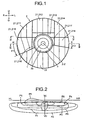
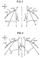
- FIG. 1 A headlight of a car will be explained as an example. Note that, in schematic diagrams shown in Figs. 3, 4 , 15 , 18 , and 19 , a hatching is omitted.
- reference sign “F” denotes the front side (traveling direction) of a car C.
- Reference sign “B” denotes the backside of the car C.
- Reference sign “U” denotes upward when a driver sees the front.
- Reference sign “D” denotes downward when the driver sees the front.
- Reference sign “L” denotes the left side when the driver sees the front.
- Reference sign “R” denotes the right side when the driver sees the front.
- Reference sign "VU-VD” denotes a vertical line on a screen.
- Reference sign "HL-HR” denotes a horizontal line on the screen.
- Reference sign "Z-Z” denotes an optical axis.
- Figs. 1 to 13 depict a vehicle light according to a first example, which is not part of the invention but is used for understanding the invention.
- the configuration of the vehicle light in the first example will be explained below.
- Respective light distribution patterns P1, P2, P3, P4, P5, P6, P7, and P8 shown In Fig. 2 and Figs. 5 to 12 , and a low-beam light distribution pattern LP shown in Fig. 13 are light distribution patterns when the driving lane is on the left side. Therefore, the light distribution patterns when the driving lane is on the right side are symmetric (reversed from left to right) to the light distribution patterns shown in Fig. 2 , Figs. 5 to 12 , and Fig. 13 .
- the vehicle light in the first example has a light source 1, a main-reflector 2, and a sub-reflector 3.
- the light source 1, the main-reflector 2, and the sub-reflector 3 are respectively arranged in a lamp chamber (not shown) sectioned by a lamp housing (not shown) and a lamp lens (not shown).
- the sub-reflector 3 is arranged around the light source 1.
- the main-reflector 2 is arranged around the light source 1 and the sub-reflector 3.
- the light source 1 has a main-filament (not shown) and a sub-filament (not shown).
- the main-reflector 2 has, as shown in Fig. 1 , a substantially circular shape as seen from the front. At substantially the center of the main-reflector 2, a substantially circular through-hole 20 is provided, through which the light source 1 is inserted.
- the main-reflector 2 is formed of a first reflection surface 21 and a second reflection surface 22 (a range surrounded by thick solid lines in Fig. 1 ). A borderline between the first reflection surface 21 and the second reflection surface 22 is, as shown in Fig.
- the first reflection surface 21 reflects light from the sub-filament as a low beam, by which the low-beam light distribution pattern LP (see Fig. 13 ) can be obtained, and reflects light from the main-filament as a high beam (not shown), by which a high-beam light distribution pattern can be obtained.
- the second reflection surface 22 reflects light from the main-filament as a high beam, by which a high-beam light distribution pattern can be obtained.
- the first reflection surface 21 and the second reflection surface 22 are designed for light distribution so that the reflected light from the main-reflector 2 does not shine onto the sub-reflector 3, and more particularly, onto the backside of the sub-reflector 3.
- the first reflection surface is largely divided into reflection surfaces in zones close to the light source 1 and the sub-reflector 3, and reflection surfaces in zones away from the light source 1 and the sub-reflector 3.
- the first reflection surface 21 is finely divided into eight zones (zones surrounded by thick solid lines in Fig. 1 ), that is, a reflection surface 211 in a first zone, a reflection surface 212 in a second zone, a reflection surface 213 in a third zone, a reflection surface 214 in a fourth zone, a reflection surface 215 in a fifth zone, a reflection surface 216 in a sixth zone, a reflection surface 217 in a seventh zone, and a reflection surface 218 in an eighth zone.
- the reflection surface 213 in the third zone, the reflection surface 216 in the sixth zone, and the reflection surface 217 in the seventh zone are reflection surfaces in the zones close to the light source 1 and the sub-reflector 3.
- the reflection surface 211 in the first zone, the reflection surface 212 in the second zone, the reflection surface 214 in the fourth zone, the reflection surface 215 in the fifth zone, and the reflection surface 218 in the eighth zone are reflection surfaces in the zones away from the light source 1 and the sub-reflector 3.
- the reflection surfaces 211 to 218 in the respective zones on the first reflection surface 21 and the second reflection surface 22 are respectively formed of one or a plurality of segments.
- the reflection surface 211 in the first zone includes three segments
- the reflection surface 212 in the second zone includes four segments
- the reflection surface 213 in the third zone includes four segments
- the reflection surface 214 in the fourth zone includes three segments
- the reflection surface 215 in the fifth zone includes three segments
- the reflection surface 216 in the sixth zone includes one segment
- the reflection surface 217 in the seventh zone includes one segment
- the reflection surface 218 in the eighth zone includes three segments
- the second reflection surface 22 includes nine segments.
- the segments are divided horizontally.
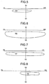
- the reflection surface 211 in the first zone reflects light from the sub-filament in a predetermined direction, thereby obtaining a substantially centralized light distribution pattern P1 shown in Fig. 5 .
- the light distribution pattern P1 is a substantially centralized light distribution pattern P1, with the upper edge thereof substantially agreeing with the upper edge of the low-beam light distribution pattern LP, having a small vertical width, and a horizontal width slightly largely protruding to the left side from a vertical line VU-VD on a screen, and slightly protruding to the right side.
- the reflection surface 212 in the second zone reflects light from the sub-filament in a predetermined direction, thereby obtaining a diffused light-distribution-pattern P2 shown in Fig. 6 .
- the light distribution pattern P2 is a diffused light-distribution-pattern P2, with the upper edge thereof substantially agreeing with the upper edge of the low-beam light distribution pattern LP, having a large vertical width, and a horizontal width largely protruding to the right and left sides from the vertical line VU-VD on the screen.
- the reflection surface 213 in the third zone reflects light from the sub-filament in a predetermined direction as a low beam LL3, avoiding the sub-reflector 3, thereby obtaining a diffused light-distribution-pattern P3 shown in Fig. 7 .
- the light distribution pattern P3 is a diffused light-distribution-pattern P3, with the upper edge thereof substantially agreeing with the upper edge of the low-beam light distribution pattern LP, having a small vertical width, and a horizontal width largely protruding to the right and left sides from the vertical line VU-VD on the screen.
- the reflection surface 214 in the fourth zone reflects light from the sub-filament in a predetermined direction, thereby obtaining a substantially centralized light distribution pattern P4 shown in Fig. 8 .
- the light distribution pattern P4 is a substantially centralized light distribution pattern P4, with the upper edge thereof substantially agreeing with the upper edge of the low-beam light distribution pattern LP, having a small vertical width, and a horizontal width slightly largely protruding to the right side from the vertical line VU-VD on the screen, and slightly protruding to the left side.
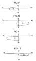
- the reflection surface 215 in the fifth zone reflects light from the sub-filament in a predetermined direction, thereby obtaining a substantially centralized light distribution pattern P5 shown in Fig. 9 .
- the light distribution pattern P5 is a substantially centralized light distribution pattern P5 that forms a triangular cutline on a driving lane side of the low-beam light distribution pattern LP, with the upper edge thereof substantially agreeing with the upper edge of the low-beam light distribution pattern LP, and having a slightly small vertical width, and a horizontal width slightly largely protruding to the left side from the vertical line VU-VD on the screen, and slightly protruding to the right side.
- the reflection surface 216 in the sixth zone reflects light from the sub-filament in a predetermined direction as a low beam LL6, avoiding the sub-reflector 3, thereby obtaining a substantially diffused light-distribution-pattern P6 shown in Fig. 10 .
- the light distribution pattern P6 is a substantially diffused light-distribution-pattern P6, with the upper edge thereof substantially agreeing with the upper edge of the low-beam light distribution pattern LP, having a slightly large vertical width, and a horizontal width slightly largely protruding to the right side from the vertical line VU-VD on the screen, and slightly protruding to the left side.
- the reflection surface 217 in the seventh zone reflects light from the sub-filament in a predetermined direction as a low beam LL7, avoiding the sub-reflector 3, thereby obtaining a substantially diffused light-distribution-pattern P7 shown in Fig. 11 .
- the light distribution pattern P7 is a substantially diffused light-distribution-pattern P7, with the upper edge thereof substantially agreeing with the upper edge of the low-beam light distribution pattern LP, having a slightly large vertical width, and a horizontal width slightly largely protruding to the left side from the vertical line VU-VD on the screen, and slightly protruding to the right side.
- the reflection surface 218 in the eighth zone reflects light from the sub-filament in a predetermined direction, thereby obtaining a substantially centralized light distribution pattern P8 shown in Fig. 12 .
- the light distribution pattern P8 is a substantially centralized light distribution pattern P8 that forms a horizontal cutline on an opposing lane side of the low-beam light distribution pattern LP, with the upper edge thereof substantially agreeing with the upper edge of the low-beam light distribution pattern LP, and having a small vertical width, and a horizontal width slightly largely protruding to the right side from the vertical line VU-VD on the screen, and slightly protruding to the left side.
- the low-beam light distribution pattern LP as shown by a solid line in Fig. 13 can be obtained.
- the light source 1 and the sub-reflector 3 are arranged close to each other, as shown in Fig. 1 . That is, the light source 1 is inserted into and arranged in the sub-reflector 3.
- the sub-reflector 3 has a cylindrical cone-shape.
- a reflection surface 30 is formed on the inner face of the sub-reflector 3.
- a supplementary light distribution pattern SP obtained by the reflection surface 30 of the sub-reflector 3 is, as shown by a broken line in Fig. 13 , in a curved shape with respect to a high luminous intensity zone HZ (or a hot zone HZ shown by a one-dot chain line in Fig. 13 ) at the upper edge of the low-beam light distribution pattern LP obtained by the first reflection surface 21 of the main-reflector 2, with the central part recessed downward, and the one end and the other end portions protruding upward.
- the vehicle light in the first example has the above configuration, and the action thereof will be explained below.
- the sub-filament of the light source is first lighted.
- the light from the sub-filament is then reflected by the reflection surfaces 211 to 218 in the respective zones on the first reflection surface 21 of the main-reflector 2.
- the reflected light illuminates the road surface and the like in the predetermined light distribution patterns P1 to P8 shown in Figs. 5 to 12 .
- the reflected light from the reflection surface 211 in the first zone illuminates the road surface and the like in the predetermined light distribution pattern P1 shown in Fig. 5 .
- the reflected light from the reflection surface 212 in the second zone illuminates the road surface and the like in the predetermined light distribution pattern P2 shown in Fig. 6 .
- the reflected light from the reflection surface 213 in the third zone illuminates the road surface and the like in the predetermined light distribution pattern P3 shown in Fig. 7 with the low beam LL3 shown in Fig. 4 , avoiding the sub-reflector 3.
- the reflected light from the reflection surface 214 in the fourth zone illuminates the road surface and the like in the predetermined light distribution pattern P4 shown in Fig. 8 .
- the reflected light from the reflection surface 215 in the fifth zone illuminates the road surface and the like in the predetermined light distribution pattern P5 shown in Fig. 9 .
- the reflected light from the reflection surface 216 in the sixth zone illuminates the road surface and the like in the predetermined light distribution pattern P6 shown in Fig. 10 with the low beam LL6 shown in Fig. 3 , avoiding the sub-reflector 3.
- the reflected light from the reflection surface 217 in the seventh zone illuminates the road surface and the like in the predetermined light distribution pattern P7 shown in Fig. 11 with the low beam LL7 shown in Fig. 3 , avoiding the sub-reflector 3.
- the reflected light from the reflection surface 218 in the eighth zone illuminates the road surface and the like in the predetermined light distribution pattern P8 shown in Fig. 12 .
- the predetermined low-beam light distribution pattern LP as shown by the solid line in Fig. 13 can be obtained.
- the light from the sub-filament is reflected by the reflection surface 30 of the sub-reflector 3.
- the reflected light illuminates the road surface and the like in the supplementary light distribution pattern SP shown by the broken line in Fig. 13 .
- the main-filament of the light source is lighted.
- the light from the main-filament is then reflected by the reflection surfaces 211 to 218 in the respective zones on the first reflection surface 21 of the main-reflector 2, and the second reflection surface 22.
- the reflected light illuminates the road surface and the like in the predetermined high-beam light distribution pattern.
- the light from the main-filament is reflected by the reflection surface 30 of the sub-reflector 3.
- the reflected light illuminates the road surface and the like in the predetermined supplementary light distribution pattern.
- the vehicle light in the first example can effectively use the light from the sub-filament of the light source 1 by reflecting the light on the reflection surfaces 211 to 218 in the respective zones on the first reflection surface 21 of the main-reflector 2, and the reflection surface 30 of the sub-reflector 3.
- the vehicle light in the first example can also effectively use the light from the main-filament of the light source 1 by reflecting the light on the reflection surfaces 211 to 218 in the respective zones on the first reflection surface 21 of the main-reflector 2, the second reflection surface 22, and the reflection surface 30 of the sub-reflector 3.
- the vehicle light in the first example can miniaturize (decreasing the sizes in the back and forth direction, in the horizontal direction, and in the vertical direction), and improve the irradiation luminous intensity (irradiation illuminance and amount of irradiation light).
- the vehicle light in the first example has the above configuration and action, and the effect thereof will be explained below.
- the vehicle light in the first example can reflect the light from the sub-filament or the light from the main-filament of the light source 1 in the predetermined direction by the reflection surfaces 211 to 218 in the respective zones on the first reflection surface 21 of the main-reflector 2, and hence, can effectively use the light from the sub-filament or the light from the main-filament of the light source 1.
- the vehicle light in the first example can reflect the light from the sub-filament of the light source, avoiding the sub-reflector 3, by the reflection surfaces on the first reflection surface 21 of the main-reflector 2, in the zones close to the light source 1 and the sub-reflector 3, that is, by the reflection surface 213 in the third zone, the reflection surface 216 in the sixth zone, and the reflection surface 217 in the seventh zone.
- the vehicle light in the first example can realize both the effective use of the reflected light from the main-reflector 2, and prevention of glare.
- the backside of the sub-reflector 3 can be subjected to the surface treatment same as that for the reflection surface 30 on the front side, for example, aluminum evaporation or silver plating.
- the treatment step becomes simple, as compared with the one in which the backside of the sub-reflector is treated in black, thereby reducing the production cost.
- the backside of the sub-reflector 3 can be colored other than black, for example, blue or orange.
- this color is projected on the reflection surface of the main-reflector, which improves the appearance, rather than the black being projected.
- the above effect can be obtained even by a vehicle light using a so-called single-filament light source or a discharge lamp, other than the so-called double-filament light source 1 having the main-filament and the sub-filament
- the light from the sub-filament is reflected in a predetermined direction, avoiding the sub-reflector 3, by the reflection surface 213 in the third zone, the reflection surface 216 in the sixth zone, and the reflection surface 217 in the seventh zone on the first reflection surface 21 of the main-reflector 2.
- the diffused light-distribution-pattern P3 in which the horizontal width largely protrudes to the right and left sides from the vertical line VU-VD on the screen the substantially diffused light-distribution-pattern P6 in which the horizontal width slightly largely protrudes to the right side from the vertical line VU-VD on the screen, and slightly protrudes to the left side
- the substantially diffused light-distribution-pattern P7 in which the horizontal width slightly largely protrudes to the left side from the vertical line VU-VD on the screen, and slightly protrudes to the right side can be formed.
- the supplementary light distribution pattern SP obtained by the reflection surface 30 of the sub-reflector 3 has a shape as shown by the broken line in Fig. 13 , that is, forms a curved shape with the central part recessed downward, and the one end and the other end portions protruding upward.
- the upper edge of the supplementary light distribution pattern SP comes out upward than the high luminous intensity zone HZ at the upper edge of the low-beam light distribution pattern LP, thereby preventing glare GZ shown by a two-dot chain line in Fig. 13 .
- the vehicle light in the first example can prevent glare GZ, and since the assembly precision of the light source 1 and the sub-reflector 3 is not necessarily required to be high, the assembly work can be simplified, thereby improving the assembly work efficiency, and reducing the production cost.
- Figs. 14 to 16 depict a vehicle light according a first embodiment of the present invention.
- the vehicle light in the first embodiment will be explained next.
- like reference signs designate like parts as those in Figs. 1 to 13 .
- the light source 1 of the vehicle light in the first embodiment has a sub-filament 10, a main-filament 11, and a shade 12.
- the sub-filament 10, the main-filament 11, and the shade 12 are arranged back and forth on an optical axis (main optical axis) Z-Z.
- the center of axis of the sub-filament 10 substantially agrees with the optical axis Z-Z.
- the upper edge of the main-filament 11 substantially agrees with the optical axis Z-Z.
- the shade 12 covers the sub-filament 10 from the lower side to the rear end thereof.
- the sub-filament 10, the main-filament 11, and the shade 12 are sealed in a glass bulb 13.
- a black top portion 14 (black head portion), for example, painted in black, which cuts off the direct light from the sub-filament 10 and the direct light from the main-filament 11, is provided at the front end of the glass bulb 13.
- a cap portion 15 for detachably fitting the light source 1 to the main-reflector 2 is provided at the rear end of the glass bulb 13.
- the main-reflector 2 of the vehicle light in the first embodiment includes the first reflection surface 21, the second reflection surface 22, and a stepped surface 23 arranged between the first reflection surface 21 and the second reflection surface 22.
- the focal length of the first reflection surface 21 is larger than that of the second reflection surface 22.
- the first reflection surface 21 is formed of a reflection surface using as a base a paraboloid designating a substantial midpoint F1 between the sub-filament 10 and the main-filament 11 as a focal point (a first focal point F1).
- the first reflection surface 21 reflects light L1 from the sub-filament 10 as a low beam LL, by which the low-beam light distribution pattern LP (see Figs. 2 and 13 ) can be obtained, and reflects light (not shown) from the main-filament 11 as a high beam (not shown), by which a high-beam light distribution pattern (not shown) can be obtained.
- the second reflection surface 22 is formed of a reflection surface using as a base a paraboloid designating a substantial central point F2 of the main-filament 11 as a focal point (a second focal point F2).
- the second reflection surface 22 reflects light L2 from the main-filament 11 as a high beam HL, by which the high-beam light distribution pattern (not shown) can be obtained.
- the light from the sub-filament 10 can not enter into the second reflection surface 22 due to the blocking action of the shade 12.
- the reflection surface 30 using as a base a paraboloid designating a point F3 at an end (a rear end) of the sub-filament 10 closer to the main-filament 11 as a focal point (a third focal point F3) is formed.
- the reflection surface 30 reflects light L3 from the sub-filament 10 as a supplementary beam SL, by which the supplementary light distribution pattern SP (see Fig. 13 ) can be obtained, and light (not shown) from the main-filament 11 as a supplementary beam (not shown), by which the supplementary light distribution pattern (not shown) can be obtained.
- the vehicle light in the first embodiment has the above configuration, similar action and effect to those of the vehicle light in the first example, can be achieved.
- the focal length of the first reflection surface 21 is made larger than that of the second reflection surface 22, the area of the first reflection surface 21 can be made wider, and hence, the luminous intensity (illuminance and amount of light) of the low-beam light distribution pattern LP can be increased, thereby improving the light distribution performance.
- the depth in the back and forth direction (F-B) of the lamp can be made small, as compared with a main-reflector 200 in which a step is not provided (a main-reflector shown by a two-dot chain line in Fig. 15 ). That is, if the area of the main-reflector 200 with no step is increased, as shown in Fig. 15 , the main-reflector 200 and the lamp lens (or an outer lens) 4 of the vehicle light interferes with each other.
- the main-reflector 200 In order to avoid the mutual intervention of the main-reflector 200 and the lamp lens 4, and increase the area of the main-reflector 200, it is necessary to displace the main-reflector 200 backward B of the lamp.
- the depth in the back and forth direction (F-B) of the lamp increases.
- the length of a standing wall (a wall not involved in the light distribution control) of the main-reflector 200 increases, thereby narrowing the range of the light distribution control, and limiting the flexibility in the light distribution design.
- the vehicle light in the first embodiment can increase the area of the first reflection surface 21, without increasing the depth in the back and forth direction (F-B) of the lamp.
- the vehicle light in the first embodiment can realize the improvement both in the flexibility in the light distribution design, and in the light distribution performance by the first reflection surface 21.
- the high-beam light distribution pattern can be easily controlled.
- the light from the sub-filament 10 is reflected as downward reflected light by the reflection surface 30 of the sub-reflector 3.
- the light can be appropriately distributed up to the close side of the vehicle.
- Figs. 17 and 18 depict a vehicle light according to a second embodiment of the present invention.
- the vehicle light in the second embodiment will be explained below.
- like reference signs designate like parts in as those in Figs. 1 to 16 .
- the main-reflector 2 of the vehicle light in the second embodiment includes the first reflection surface 21 and the second reflection surface 22, using as a base a paraboloid designating the vicinity of a light-emitting portion 16 of the light source 1 as a focal point F, and the stepped surface 23 arranged between the first reflection surface 21 and the second reflection surface 22, into which light L4 from the light-emitting portion 16 of the light source 1 does not enter.
- An angle ⁇ 3 between the stepped surface 23 and the optical axis Z-Z is, as shown in Fig. 18 , such that the light L4 from the light-emitting portion 16 of the light source 1 does not enter into the stepped surface 23.
- the sub-reflector 3 is arranged at a position between reflected light L5 from the first reflection surface 21 and reflected light L6 from the second reflection surface 22, and a position through which the reflected light L5 from the first reflection surface 21 and the reflected light L6 from the second reflection surface 22 do not pass.
- the vehicle light in the second embodiment has the above configuration, the action and the effect similar to those of the vehicle lights in the first example and the first embodiment can be achieved.
- the stepped surface 23 is not involved in the light distribution control.
- a design 24 such as a pattern, color, character, figure, or sign can be applied to the stepped surface 23, and hence, a new design or a new appearance can be obtained.
- the light source 1 may be a double-filament light source having a sub-filament and a main-filament, a single-filament light source, or a discharge lamp.
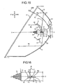
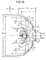
- Fig. 19 depicts a vehicle light according to a second example of the present invention.
- the vehicle light in the second example will be explained below.
- like reference signs designate like parts as those in Figs. 1 to 18 .
- a through-hole 20 through which the light source 1 is inserted is provided substantially at the center of the main-reflector 2 of the vehicle light in the second example.
- a diffuse reflection surface 25 that forms a diffused light-distribution-pattern (not shown) is provided at the peripheral edge of the through-hole 20 of the main-reflector 2. That is, the diffuse reflection surface 25 reflects light L7 from the light source 1 as a diffused light WL.
- the diffuse reflection surface 25 is formed of a curved surface obtained by rotating a spheroid or a paraboloid about a predetermined axis, or a curved surface obtained by bending a paraboloid.
- the vehicle light in the second example has the above configuration, the action and the effect similar to those of the vehicle light in the first example and the first and second embodiments can be achieved.
- the light L7 from the light source 1 is reflected as a diffused light WL by the diffuse reflection surface 25 provided at the peripheral edge of the through-hole 20 of the main-reflector 2, to obtain the diffused light-distribution-pattern.
- the vehicle light in the second example can use the L7 from the light source 1 more effectively.
- the depth T1 in the back and forth direction (F-B) and the width W 1 in the left and right direction (L-R) of the lamp may be smaller than the depth T2 and the width W2 of the main-reflector 201 (main-reflector shown by a two-dot chain line in Fig. 19 ), in which the diffuse reflection surface is not provided at the peripheral edge of the through-hole. That is, with the main-reflector 201 in which the diffuse reflection surface is not provided at the peripheral edge of the through-hole, when the light from the light source is to be used more effectively, it is necessary to increase the depth T2 and the width W2.
- the light source 1 may be a double-filament light source having a sub-filament and a main-filament, a single-filament light source, or a discharge lamp.
Landscapes
- Engineering & Computer Science (AREA)
- General Engineering & Computer Science (AREA)
- Non-Portable Lighting Devices Or Systems Thereof (AREA)
Claims (9)
- Fahrzeuglampe, aufweisend eine Lichtquelle (1), einen Hauptreflektor (2) und einen Nebenreflektor (3), wobeider Nebenreflektor (3) rund um die Lichtquelle (1) angeordnet ist,der Hauptreflektor (2) rund um die Lichtquelle (1) und den Nebenreflektor (3) angeordnet ist;
wobei der Hauptreflektor (2) eine Reflektionsoberfläche (21, 22) enthält, die Licht von der Lichtquelle (1) in eine vorbestimmte Richtung unter Vermeidung des Nebenreflektors (3) reflektiert,
wobei die Lichtquelle (1) einen Haupt- Glühfaden und einen Neben- Glühfaden enthält,der Hauptreflektor (2) eine erste Reflektionsoberfläche (21) und eine zweite Reflektionsoberfläche (22) enthält,
wobei die erste Reflektionsoberfläche (21) Licht von dem Neben- Glühfaden als ein Abblendlicht reflektiert, durch das ein Abblendlicht- Verteilungsmuster erhalten wird, und Licht von dem Haupt- Glühfaden als ein Fernlicht reflektiert, durch das ein Fernlicht- Verteilungsmuster erhalten wird,die zweite Reflektionsoberfläche (22) das Licht von dem Haupt- Glühfaden als ein Fernlicht reflektiert, durch das ein Fernlicht- Verteilungsmuster erhalten wird,
dadurch gekennzeichnet, dassdie erste Reflektionsoberfläche (21) in eine nahe Reflektionsoberfläche in einer Zone, nahe zu der Lichtquelle (1) und dem Nebenreflektor (3), und eine entfernte Reflektionsoberfläche in einer Zone, entfernt von der Lichtquelle (1) und dem Nebenreflektor (3), geteilt ist,wodurch sich die nahe Reflektionsobefläche und die entfernte Reflektionsoberfläche einander nicht überlappen, wobei die nahe Reflektionsoberfläche zu dem Nebenreflektor (3) und der Lichtquelle (1) benachbart ist und eine gestufte Oberfläche (23) zwischen der ersten Reflektionsoberfläche (21) und der zweiten Reflektionsoberfläche (22) angeordnet ist. - Fahrzeuglampe nach Anspruch 1, wobei die nahe Reflektionsoberfläche das Licht von dem Neben- Glühfaden in eine vorbestimmte Richtung unter Vermeidung des Nebenreflektors (3) reflektiert und in dem Abblendlicht- Verteilungsmuster zumindest ein Licht- Verteilungsmuster unter einem ersten Licht- Verteilungsmuster, einem zweiten Licht- Verteilungsmuster und einem dritten Licht- Verteilungsmuster erhält, wobei das erste Licht- Verteilungsmuster ein gestreutes Licht- Verteilungsmuster ist, in dem eine horizontale Breite weit nach rechts und nach links von einer vertikalen Linie auf einem Schirm vorspringt,
das zweite Licht- Verteilungsmuster ein im Wesentlichen gestreutes Licht- Verteilungsmuster ist, in dem die horizontale Breite nur wenig weit nach rechts von der vertikalen Linie auf dem Schirm vorspringt und nur wenig weit nach links von der vertikalen Linie auf dem Schirm vorspringt
das dritte Licht- Verteilungsmuster ein im Wesentlichen gestreutes Licht- Verteilungsmuster ist, in dem die horizontale Breite nur wenig weiter nach links von der vertikalen Linie auf dem Schirm vorspringt und leicht nach rechts von der vertikalen Linie auf dem Schirm vorspringt. - Fahrzeuglampe nach Anspruch 1, wobei
die nahe Reflektionsoberfläche das Licht von dem Neben- Glühfaden in einer vorbestimmten Richtung unter Vermeidung des Nebenreflektors reflektiert und in dem Abblendlicht- Verteilungsmuster in eine dritte Reflektionsoberfläche (213), eine vierte Reflektionsoberfläche (216) und eine fünfte Reflektionsoberfläche (217) geteilt ist, wobei die dritte Reflektionsobertläche (213) eine Reflektionsoberfläche in einer Zone ist, wo ein gestreutes Licht- Verteilungsmuster erhalten wird, in dem eine horizontale Breite weit nach rechts und nach links von einer vertikalen Linie auf einem Schirm vorspringt,
die vierte Reflektionsoberfläche (216) eine Reflektionsoberfläche in einer Zone ist, wo ein im Wesentlichen gestreutes Licht- Verteilungsmuster erhalten wird, in dem die horizontale Breite nur wenig weiter nach rechts von der vertikalen Linie auf dem Schirm vorspringt und nur wenig nach links von der vertikalen Linie auf dem Schirm vorspringt, und
die fünfte Reflektionsoberfläche (217) eine Reflektionsoberfläche in einer Zone ist, wo ein im Wesentlichen gestreutes Licht- Verteilungsmuster erhalten wird, in dem die horizontale Breite nur wenig weiter nach links von der vertikalen Linie auf dem Schirm vorspringt und wenig nach rechts von der vertikalen Linie auf dem Schirm vorspringt, und
die entfernte Reflektionsoberfläche in dem Fernlicht- Verteilungsmuster in eine sechste Reflektionsoberfläche (211), eine siebente Reflektionsoberfläche (212), eine achte Reflektionsoberfläche (214), eine neunte Reflektionsoberfläche (215) und eine zehnte Reflektionsoberfläche (218) geteilt ist, wobei
die sechste Reflektionsoberfläche (211) eine Reflektionsoberfläche in einer Zone ist, wo ein im Wesentlichen zentralisiertes Licht- Verteilungsmuster erhalten wird, in dem die horizontale Breite nur wenig weiter nach links von der vertikalen Linie auf dem Schirm vorspringt und ein wenig nach rechts von der vertikalen Linie auf dem Schirm vorspringt,
die siebente Reflektionsoberfläche (212) eine Reflektionsoberfläche in einer Zone ist, wo ein gestreutes Licht- Verteilungsmuster erhalten wird, in dem die horizontale Breite weit nach rechts und nach links von der vertikalen Linie VU-VD auf dem Schirm vorspringt,
die achte Reflektionsoberfläche (214) eine Reflektionsoberfläche in einer Zone ist, wo ein im Wesentlichen zentralisiertes Licht- Verteilungsmuster erhalten wird, in dem die horizontale Breite wenig weit nach rechts von der vertikalen Linie auf dem Schirm vorspringt und nur wenig nach links von der vertikalen Linie auf dem Schirm vorspringt,
die neunte Reflektionsoberfläche (215) eine Reflektionsoberfläche in einer Zone ist, wo ein Licht- Verteilungsmuster erhalten wird, das eine dreiseitige Schnittlinie auf einer Fahrerseite bildet, erhalten wird, und
die zehnte Reflektionsoberfläche (218) eine Reflektionsoberfläche in einer Zone ist, wo ein Licht- Verteilungsmuster erhalten wird, das eine horizontale Schnittlinie auf einer gegenüberliegenden Fahrspurseite bildet. - Fahrzeuglampe nach Anspruch 1, wobei
die Lichtquelle (1) und der Nebenreflektor (3) nahe zueinander angeordnet sind, und
ein Licht- Verteilungsmuster, das durch den Nebenreflektor (3) erhalten wird, eine gekrümmte Form in Bezug auf eine Zone hoher Beleuchtungsintensität an einer oberen Kante eines Licht- Verteilungsmusters aufweist, das durch den Hauptreflektor (2) erhalten wird, mit einem zentralen, nach unten ausgesparten Abschnitt, und mit einem Ende und andere Endabschnitte nach oben vorspringen. - Fahrzeuglampe nach Anspruch 4, wobei
ein Licht- Verteilungsmuster, erhalten durch den Hauptreflektor (2), ein Abblendlicht- Verteilungsmuster ist. - Fahrzeuglampe nach Anspruch 1, wobei
der Hauptreflektor (2) die erste Reflektionsoberfläche (21) und die zweite Reflektionsoberfläche (22) enthält, deren Basis ein Paraboloid ist, bei dem eine Umgebung eines lichtemittierenden Abschnittes der Lichtquelle (1) einen Brennpunkt bezeichnet,
und eine Brennweite der ersten Reflektionsoberfläche (21) länger als die der zweiten Reflektionsoberfläche (22) ist. - Fahrzeuglampe nach Anspruch 1, wobei
der Hauptreflektor (2) enthält die erste Reflektionsoberfläche (21) und die zweite Reflektionsoberfläche (22), deren Basis ein Paraboloid ist, bei dem eine Umgebung eines lichtemittierenden Abschnittes der Lichtquelle (1) einen Brennpunkt bezeichnet, und eine gestufte Oberfläche (23) zwischen der ersten Reflektionsoberfläche (21) und der zweiten Reflektionsoberfläche (22) angeordnet ist, in die das Licht von der Lichtquelle (1) nicht eindringt; und
der Nebenreflektor (3) an einer Position zwischen dem Licht, reflektiert von der ersten Reflektionsoberfläche (21), und dem Licht, reflektiert von der zweiten Reflektionsobertläche (22), angeordnet ist, die eine Position ist, durch die das Licht, reflektiert von der ersten Reflektionsoberfläche (21), und das Licht, reflektiert von der zweiten Reflektionsoberfläche (22), nicht hindurchgeht. - Fahrzeuglampe nach Anspruch 1, wobei
eine Durchgangsbohrung (20), durch die die Lichtquelle (1) eingesetzt wird, im Wesentlichen in einer Mitte des Hauptreflektors (2) vorgesehen ist, und
eine Streu- Reflektionsoberfläche (25), die ein gestreutes Licht- Verteilungsmuster bildet, an einer Umfangskante der Durchgangsbohrung (20) an dem Hauptreflektor (2) vorgesehen ist. - Fahrzeuglampen mach Anspruch 1, wobei
die erste Reflektionsoberfläche (21) eine Reflektionsoberfläche enthält, deren Basis ein Paraboloid ist, bei dem im Wesentlichen ein Mittelpunkt zwischen dem Haupt- Glühfaden (11) und dem Neben- Glühfaden (10) einen Brennpunkt bildet, die Licht von dem Neben- Glühfaden (10) als ein Abblendlicht reflektiert, wodurch ein Abblendlicht- Verteilungsmuster erhalten wird, und Licht von dem Haupt-Glühfaden (11) als ein Fernlicht reflektiert, wodurch ein Fernlicht- Verteilungsmuster erhalten wird,
die zweite Reflektionsoberfläche (22) eine Reflektionsoberfläche enthält, deren Basis ein Paraboloid ist, bei den im Wesentlichen ein zentraler Punkt des Haupt-Glühfadens (11) einen Brennpunkt bildet, die Licht von dem Haupt- Glühfaden (11) als ein Fernlicht- Verteilungsmuster reflektiert, wodurch ein Fernlicht- Verteilungsmuster erhalten wird,
und
der Nebenreflektor (3) eine Reflektionsoberfläche (30) enthält, deren Basis ein Paraboloid ist, bei dem ein Punkt an einem Ende des Neben- Glühfadens (10), näher zu dem Haupt- Glühfaden (11), einen Brennpunkt bildet.
Applications Claiming Priority (2)
| Application Number | Priority Date | Filing Date | Title |
|---|---|---|---|
| JP2003402125 | 2003-12-01 | ||
| JP2003402125A JP2005166371A (ja) | 2003-12-01 | 2003-12-01 | 車両用灯具 |
Publications (3)
| Publication Number | Publication Date |
|---|---|
| EP1538392A2 EP1538392A2 (de) | 2005-06-08 |
| EP1538392A3 EP1538392A3 (de) | 2006-11-02 |
| EP1538392B1 true EP1538392B1 (de) | 2009-02-18 |
Family
ID=34463939
Family Applications (1)
| Application Number | Title | Priority Date | Filing Date |
|---|---|---|---|
| EP04028375A Expired - Lifetime EP1538392B1 (de) | 2003-12-01 | 2004-11-30 | Fahrzeugleuchte |
Country Status (4)
| Country | Link |
|---|---|
| US (1) | US7178958B2 (de) |
| EP (1) | EP1538392B1 (de) |
| JP (1) | JP2005166371A (de) |
| DE (1) | DE602004019489D1 (de) |
Families Citing this family (15)
| Publication number | Priority date | Publication date | Assignee | Title |
|---|---|---|---|---|
| JP2006019049A (ja) * | 2004-06-30 | 2006-01-19 | Ichikoh Ind Ltd | 車両用灯具 |
| US7862213B2 (en) * | 2005-01-18 | 2011-01-04 | Musco Corporation | Modified reflector surface to redirect off-field side light onto field |
| JP2008041557A (ja) * | 2006-08-09 | 2008-02-21 | Ichikoh Ind Ltd | 車両用前照灯用の灯具ユニット |
| ATE439551T1 (de) * | 2006-09-19 | 2009-08-15 | Peugeot Citroen Automobiles Sa | Kraftfahrzeugscheinwerfer mit zwei funktionen |
| FR2911663B1 (fr) * | 2007-01-22 | 2009-04-17 | Valeo Vision Sa | Module optique multifonction de vehicule automobile |
| DE102007062136A1 (de) * | 2007-12-21 | 2009-06-25 | Hella Kgaa Hueck & Co. | Scheinwerfer für Fahrzeuge |
| JP4582190B2 (ja) * | 2008-05-14 | 2010-11-17 | 市光工業株式会社 | 車両用灯具 |
| JP5264448B2 (ja) | 2008-12-02 | 2013-08-14 | 株式会社小糸製作所 | 投射型の車両用灯具 |
| US8033693B2 (en) * | 2009-04-30 | 2011-10-11 | Avago Technologies Ecbu Ip (Singapore) Pte. Ltd. | Lighting structure with multiple reflective surfaces |
| JP2010262750A (ja) * | 2009-04-30 | 2010-11-18 | Koito Mfg Co Ltd | 車両用灯具 |
| JP5618721B2 (ja) * | 2010-09-13 | 2014-11-05 | 株式会社小糸製作所 | レンズの製造方法 |
| JP7058166B2 (ja) * | 2018-04-10 | 2022-04-21 | 株式会社小糸製作所 | 車両用前照灯 |
| EP3772610B1 (de) * | 2019-08-06 | 2022-04-20 | Nichia Corporation | Beleuchtungsvorrichtung |
| US11187393B1 (en) * | 2020-12-30 | 2021-11-30 | Valeo Vision | Light system with cut-off |
| JP7577631B2 (ja) * | 2021-09-03 | 2024-11-05 | 株式会社遠藤照明 | 照明装置 |
Family Cites Families (7)
| Publication number | Priority date | Publication date | Assignee | Title |
|---|---|---|---|---|
| JP2504584B2 (ja) | 1989-09-26 | 1996-06-05 | ローレルバンクマシン株式会社 | 貨幣処理機におけるユニット調整スイッチ機構 |
| DE4023408A1 (de) * | 1990-07-23 | 1992-01-30 | Delma Elektro Med App | Operationsleuchte |
| JP2527274B2 (ja) * | 1990-11-19 | 1996-08-21 | 株式会社小糸製作所 | 自動車用ヘッドランプ |
| US6068388A (en) * | 1996-02-28 | 2000-05-30 | Eppi Lighting, Inc. | Dual reflector lighting system |
| DE19632189A1 (de) * | 1996-08-09 | 1998-02-12 | Bosch Gmbh Robert | Scheinwerfer für Fahrzeuge |
| US7036967B2 (en) * | 2002-12-24 | 2006-05-02 | Ichikoh Industries, Ltd. | Vehicle lamp |
| JP2004259541A (ja) * | 2003-02-25 | 2004-09-16 | Cateye Co Ltd | 照明器具 |
-
2003
- 2003-12-01 JP JP2003402125A patent/JP2005166371A/ja active Pending
-
2004
- 2004-11-30 DE DE602004019489T patent/DE602004019489D1/de not_active Expired - Lifetime
- 2004-11-30 EP EP04028375A patent/EP1538392B1/de not_active Expired - Lifetime
- 2004-12-01 US US11/000,518 patent/US7178958B2/en not_active Expired - Fee Related
Also Published As
| Publication number | Publication date |
|---|---|
| JP2005166371A (ja) | 2005-06-23 |
| EP1538392A3 (de) | 2006-11-02 |
| US20050141233A1 (en) | 2005-06-30 |
| US7178958B2 (en) | 2007-02-20 |
| EP1538392A2 (de) | 2005-06-08 |
| DE602004019489D1 (de) | 2009-04-02 |
Similar Documents
| Publication | Publication Date | Title |
|---|---|---|
| JP3005687B2 (ja) | 灯 具 | |
| EP0949449B1 (de) | Fahrzeuglampe mit asphärischen Linsen und dazugehörende Blenden | |
| US6402355B1 (en) | Vehicular headlamp having improved low-beam illumination | |
| EP1538392B1 (de) | Fahrzeugleuchte | |
| US6435703B2 (en) | Vehicular headlamp | |
| US6416210B1 (en) | Headlamp for a vehicle | |
| EP0950847B1 (de) | Lampe, insbesondere für Fahrzeuge oder Verkehrssignalanlagen | |
| CN106969311A (zh) | 车辆用灯具 | |
| JPH09237504A (ja) | 下向き及び上向きライト用自動車前照灯 | |
| JP2003123517A (ja) | 投光ユニットおよび該投光ユニットを具備するled車両用照明灯具 | |
| US6457850B2 (en) | Vehicle lamp | |
| US6471383B1 (en) | Headlamp for vehicle | |
| US6200006B1 (en) | Vehicle Lamp | |
| JP4536859B2 (ja) | 車両に用いられるヘッドライト | |
| EP1538021B1 (de) | Fahrzeugleuchte | |
| US6328463B1 (en) | Automobile headlamp | |
| KR100294931B1 (ko) | 차량용전조등 | |
| US6341885B1 (en) | Vehicle lamp | |
| JPH10261302A (ja) | プロジェクタ型ランプ | |
| JP4009452B2 (ja) | 横長レンズプロジェクター型ヘッドランプ | |
| JP2008041597A (ja) | 車両用前照灯 | |
| EP1338468A2 (de) | Leuchte für Fahrzeuge | |
| EP0864803B1 (de) | Scheinwerfer für Kraftfahrzeuge | |
| JPS60216401A (ja) | 車両用前照灯 | |
| KR200156486Y1 (ko) | 자동차용 전조등 |
Legal Events
| Date | Code | Title | Description |
|---|---|---|---|
| PUAI | Public reference made under article 153(3) epc to a published international application that has entered the european phase |
Free format text: ORIGINAL CODE: 0009012 |
|
| 17P | Request for examination filed |
Effective date: 20041130 |
|
| AK | Designated contracting states |
Kind code of ref document: A2 Designated state(s): AT BE BG CH CY CZ DE DK EE ES FI FR GB GR HU IE IS IT LI LU MC NL PL PT RO SE SI SK TR |
|
| AX | Request for extension of the european patent |
Extension state: AL HR LT LV MK YU |
|
| PUAL | Search report despatched |
Free format text: ORIGINAL CODE: 0009013 |
|
| AK | Designated contracting states |
Kind code of ref document: A3 Designated state(s): AT BE BG CH CY CZ DE DK EE ES FI FR GB GR HU IE IS IT LI LU MC NL PL PT RO SE SI SK TR |
|
| AX | Request for extension of the european patent |
Extension state: AL HR LT LV MK YU |
|
| 17Q | First examination report despatched |
Effective date: 20061222 |
|
| AKX | Designation fees paid |
Designated state(s): DE FR GB |
|
| 17Q | First examination report despatched |
Effective date: 20061222 |
|
| GRAP | Despatch of communication of intention to grant a patent |
Free format text: ORIGINAL CODE: EPIDOSNIGR1 |
|
| RIN1 | Information on inventor provided before grant (corrected) |
Inventor name: MATSUMOTO, KAZUHIROC/O ICHIKOH INDUSTRIES, LTD. Inventor name: KOBAYASHI, MASAFUMIC/O ICHIKOH INDUSTRIES, LTD. Inventor name: IWASAKI, KAZUNORIC/O ICHIKOH INDUSTRIES, LTD. |
|
| GRAS | Grant fee paid |
Free format text: ORIGINAL CODE: EPIDOSNIGR3 |
|
| GRAA | (expected) grant |
Free format text: ORIGINAL CODE: 0009210 |
|
| AK | Designated contracting states |
Kind code of ref document: B1 Designated state(s): DE FR GB |
|
| REG | Reference to a national code |
Ref country code: GB Ref legal event code: FG4D |
|
| REF | Corresponds to: |
Ref document number: 602004019489 Country of ref document: DE Date of ref document: 20090402 Kind code of ref document: P |
|
| PLBE | No opposition filed within time limit |
Free format text: ORIGINAL CODE: 0009261 |
|
| STAA | Information on the status of an ep patent application or granted ep patent |
Free format text: STATUS: NO OPPOSITION FILED WITHIN TIME LIMIT |
|
| 26N | No opposition filed |
Effective date: 20091119 |
|
| PGFP | Annual fee paid to national office [announced via postgrant information from national office to epo] |
Ref country code: DE Payment date: 20121128 Year of fee payment: 9 Ref country code: FR Payment date: 20121130 Year of fee payment: 9 |
|
| PGFP | Annual fee paid to national office [announced via postgrant information from national office to epo] |
Ref country code: GB Payment date: 20121128 Year of fee payment: 9 |
|
| GBPC | Gb: european patent ceased through non-payment of renewal fee |
Effective date: 20131130 |
|
| REG | Reference to a national code |
Ref country code: FR Ref legal event code: ST Effective date: 20140731 |
|
| REG | Reference to a national code |
Ref country code: DE Ref legal event code: R119 Ref document number: 602004019489 Country of ref document: DE Effective date: 20140603 |
|
| PG25 | Lapsed in a contracting state [announced via postgrant information from national office to epo] |
Ref country code: DE Free format text: LAPSE BECAUSE OF NON-PAYMENT OF DUE FEES Effective date: 20140603 |
|
| PG25 | Lapsed in a contracting state [announced via postgrant information from national office to epo] |
Ref country code: FR Free format text: LAPSE BECAUSE OF NON-PAYMENT OF DUE FEES Effective date: 20131202 Ref country code: GB Free format text: LAPSE BECAUSE OF NON-PAYMENT OF DUE FEES Effective date: 20131130 |