EP1538366A1 - Bypassventil für Schwingungsdämpfer - Google Patents
Bypassventil für Schwingungsdämpfer Download PDFInfo
- Publication number
- EP1538366A1 EP1538366A1 EP04026369A EP04026369A EP1538366A1 EP 1538366 A1 EP1538366 A1 EP 1538366A1 EP 04026369 A EP04026369 A EP 04026369A EP 04026369 A EP04026369 A EP 04026369A EP 1538366 A1 EP1538366 A1 EP 1538366A1
- Authority
- EP
- European Patent Office
- Prior art keywords
- guide body
- bypass valve
- slide
- lock slider
- valve according
- Prior art date
- Legal status (The legal status is an assumption and is not a legal conclusion. Google has not performed a legal analysis and makes no representation as to the accuracy of the status listed.)
- Granted
Links
Images

Classifications
-
- F—MECHANICAL ENGINEERING; LIGHTING; HEATING; WEAPONS; BLASTING
- F16—ENGINEERING ELEMENTS AND UNITS; GENERAL MEASURES FOR PRODUCING AND MAINTAINING EFFECTIVE FUNCTIONING OF MACHINES OR INSTALLATIONS; THERMAL INSULATION IN GENERAL
- F16F—SPRINGS; SHOCK-ABSORBERS; MEANS FOR DAMPING VIBRATION
- F16F9/00—Springs, vibration-dampers, shock-absorbers, or similarly-constructed movement-dampers using a fluid or the equivalent as damping medium
- F16F9/32—Details
- F16F9/44—Means on or in the damper for manual or non-automatic adjustment; such means combined with temperature correction
- F16F9/46—Means on or in the damper for manual or non-automatic adjustment; such means combined with temperature correction allowing control from a distance, i.e. location of means for control input being remote from site of valves, e.g. on damper external wall
- F16F9/466—Throttling control, i.e. regulation of flow passage geometry
Definitions
- the invention relates to a bypass valve of a hydraulic damper, via which a first working space of the vibration damper with a second Workspace of the same hydraulically coupled, with a one shaft and a trained as a hollow body slide valve having valve slide, wherein the lock slider by a stationary, at least partially hollow guide body is mounted axially displaceable and with at least one in the jacket the guide body arranged breakthrough cooperates such that the free cross-section of the aperture by axial movement of the control slide changeable is, and with an actuator for moving the control slide in the axial Direction.
- bypass valves are known from the prior art (DE 40 11 358 C1).
- bypass valve forms the hollow Piston rod the guide cylinder, in the interior of the slide valve axially slidably arranged.
- the control slide has a valve basket called hollow cylindrical section on, by the axial displacement of the Locking slide the free cross section provided in the lateral surface of the piston rod Bypass openings is infinitely adjustable. That's how it works Damping behavior of the vibration damper continuously adjusted.
- the axial displacement of the adjusting slide takes place here by the inside of the piston rod arranged electric motor.
- the invention is based on the object, a bypass valve of the above so-called type in such a way that the of the damping fluid the locking slide transmitted disturbing forces are minimized.
- a bypass valve of the above so-called type in such a way that the of the damping fluid the locking slide transmitted disturbing forces are minimized.
- the slide valve even at maximum pressure difference between the working chambers of the vibration damper safely and accurately in the provided parking position moves and can be held there.
- this object is achieved in that the guide body is arranged axially and radially stationary and the lock slider larger than the guide body is formed, so that the guide body is a guide pin forms, on which the lock slider is guided axially displaceable.
- the axially and radially fixed guide body takes the main part of the generated by the flowing damping fluid Disruptive forces.
- the lock slider is used as a moving component of This Stör law largely decoupled, so that a safe and accurate setting the set position of the control slide in each operating condition of the Vibration damper is guaranteed. Even at maximum pressure difference between The working spaces of the vibration damper thus act on the lock slider only a very small amount of disturbing forces, so that it is safe in any case and can be moved exactly to its desired parking position and held there.
- bypass valves which the working spaces of the rebound and compression stage of a vibration damper connect together, at different points of the vibration can be provided. So it is e.g. possible, as in DE 40 11 358 C1 described, the valve spool and the associated actuator in the piston rod to integrate the vibration damper. Likewise, it is e.g. possible, that Bypass valve in a separate module housing to integrate, which outside the container tube of the vibration damper is attached and via holes connected in the container wall with the working spaces of the vibration damper is (backpack valve). In the present invention, it does not matter which point the bypass valve is arranged.
- the bypass valve according to the invention is basically suitable for all known arrangement variants.
- the lock slider and the guide body are each formed as a hollow cylinder, so cylindrical Have cross sections.
- cylindrical Have cross sections it is also possible in principle, from the cylindrical shape departing.
- a straight cut peripheral area be provided, through which the hollow cylindrical shape flattened in a peripheral region becomes.
- Such a shape becomes a defined and rotationally fixed positioning reaches the slide to the guide body.
- a robust construction of the valve is achieved by the hollow Locking slide and the shaft of the valve spool are integrally formed and thus form an integral component.
- the hollow lock slider as a separate, e.g. be formed sleeve-shaped component (which is basically possible), so would have a reliable, permanent joint connection between the adjusting sleeve and the shaft are ensured. This joint connection is against not required if the stem and the hollow valve are in one piece as integral Component are executed.
- the actuator can therefore be used as a simple electromechanical linear drive, e.g. of the solenoid type.
- the solenoid type has the lock slider the function of an anchor, by a current-controlled electromagnet in the axial direction is movable back and forth. Due to the amperage, with the the solenoid is controlled, the desired setting position of the control slide set.
- a seat valve To close the bypass valve and thus a permanent leakage of Valve to avoid, it is advantageously designed as a seat valve.
- a radially extending on the guide body Paragraph formed with the free end of the hollow lock slider after the Principle valve / valve seat cooperates. It forms the free end of the Slider facing surface of the paragraph the valve seat on which the free end of the lock valve is sealingly placed. It is understood that in In this case, the breakthrough in the shell of the guide body above the paragraph is arranged so that its free cross section by the axial displacement of the Locking slide is adjustable.
- At least one relief groove in the surface of the guide body intended.
- the relief grooves assume the function of a hydraulic bearing.
- Advantageous are the relief grooves above the breakthrough in the inner surface introduced the hollow locking slide facing lateral surface of the guide body.
- a spacer provided coaxially with the lock slider and the guide body is arranged.
- the spacer surrounds the lock slider and is spaced from the control slide.
- an annular space which also serves as a discharge chamber can be designated.
- Breakthroughs provided via which the annulus to the working space of the rebound the vibration damper is connected.
- the annulus is in the inventive Bypass valve provided to the flow of damping fluid to influence specifically.
- the flow shape the damping fluid can be influenced so that a flow share the Chamber immediately leaves through the breakthroughs, while the remaining flow fraction deflected in the chamber and directed to the end face of the lock slider is, so that this flow fraction used to compensate for the disturbing forces can be.
- a pressure equalization hole provided in the shaft of the valve spool, which is the space on the back of the Valve spool and the outflow chamber connects to each other.
- the Locking slide have one or more openings.
- the respective openings in the guide body and in the Lockpads are set freely to each other, which Studentsdeckungsgrad the Breakthroughs should be present in the de-energized state.
- the breakthroughs in these two components e.g. be arranged so that they are in the de-energized state cover each other in half, so that only half of the breakthrough area is freely flowed through. Then the vibration damper points in the case of a sudden Power failure on a medium damping behavior.
- the bypass valve In order to minimize the energy consumption for the damping force control, It makes sense, so the breakthrough in the lateral surface of the guide body Position the bypass valve in the de-energized state.
- the bypass valve mainly causes the damping force of the vibration damper, so that the damping behavior is essentially different from the others Valves of the vibration damper is determined. So can in the vibration damper
- a so-called comfort valve which has a comparatively soft damping characteristic and the damping mode characterized in the motor vehicles, according to experience mainly operate. If the bypass valve is open when de-energized, then the Flow path to the comfort valve open and most of the damper work is taken over by the comfort valve.
- the bypass valve according to the invention can shock absorbers with one and two-chamber operating principle be used. Is the bypass valve in a separate Module housing integrated, so can one or two modules in itself known manner as backpack valves outside the container tube of the damper be attached. For example, in a monotube shock absorber independent of one another To enable adjustment of the rebound and compression, two can Externadaptiere modules containing the bypass valve according to the invention, be attached as a backpack valves on the container tube of the Schwindungsdämpfers. The one module works only in rebound, while the other Module is effective only in the compression stage. That way, that way called skyhook capability of vehicle damping can be achieved.
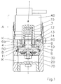
- the bypass valve shown in Fig. 1 is designed as a backpack valve module, which on the outside of the container tube (not shown) adaptable in a conventional manner is.
- the valve comprises a module housing 20, in which a comfort valve 30 is arranged axially fixed with non-return function and radially.
- This comfort valve 30 acts in a known manner as a damping valve between the train and Pressure level of the (not shown) vibration damper.
- Comfort valve 30 seen from downstream a hollow cylindrical guide cylinder 6, which also axially and radially fixed in the module housing 20th is held.
- the guide cylinder 6 has at its the comfort valve 30th facing end in a radial direction to the module housing 20 back extending paragraph 9, through which the guide cylinder 6 in the axial and radial Direction fixed to the module housing 20 is held.
- the hollow cylindrical portion 6a extends of the guide cylinder 6, so that this hollow cylindrical part 6a a guide pin forms, on which a hollow cylindrical lock slider 4 axially displaceable is guided.
- the lock slider 4 integrally formed with the shaft 3 of the valve spool 1.
- the shaft 3 forms an armature which is axially movable within the coil of a current-controlled electromagnet 40 is arranged.
- Electromagnet 40 forms with the armature 3 an electromechanical linear drive, which serves as actuator A for the lock slider 4.
- the hollow cylindrical lock slider 4 is enclosed by an annular Distance element 13. Between the spacer element 13 and the lock slider 4 is an inner annular space 14 is provided which over in the wall of the spacer element 13 arranged holes 50 connected to an outer annular space 60 is.
- This annulus 60 can either with the working space of the train or the compression of the (not shown in Fig. 1) vibration damper on a Coupling hole K be connected. With which working space the annular space 60 connected depends on which stage (train or pressure) the comfort valve 30 is to develop its damping effect.
- openings 8 are present.
- the free cross section of these openings 8 can be achieved by axial displacement of the Locking slide 4 can be adjusted.
- the openings 8 completely releases, the outer annular space 60 with the space 70 with interposition the comfort valve 30 hydraulically coupled. In this state will the damping behavior of the backpack valve by the comfort valve 30th certainly.
- the space 70 with the pressure stage of the vibration damper, not shown, while the outer annular space 60 is connected to the rebound of the vibration damper is. Moves the piston rod of the vibration damper under load Vibration damper on, so damping fluid from the compression stage in the Room 70 and from this via the comfort valve 30 into the interior of the hollow cylindrical Guide cylinder 6 transported.
- the comfort valve 30 calls a Damping force. From the interior of the hollow cylindrical guide cylinder 6, the damping fluid flows through the openings 8 in the inner Annulus 14 and from there through the holes 50 in the outer annulus 60, which in turn connected to the rebound of the vibration damper is. In this case, the free cross section of the apertures 8 unfolds a throttle effect. This throttling effect can be achieved by a targeted axial displacement of the adjusting slide 4, which leads to a reduction of the free cross section of the openings. 8 leads to a targeted increase. In this way, the damping behavior can be set the backpack valve continuously.
- the axial displacement of the adjusting slide 4 on the guide cylinder 6 takes place in a manner known per se from the prior art by a change the drive current with which the electromagnet 40 is driven.
- the the Locking slide 4 facing surface of the paragraph 9 forms a valve seat surface 10, on which the lock slider 4 is sealingly placed with its end face, so there is no leakage.
- the wall of the hollow cylindrical adjusting slide 4 has a chamfer 11 on the end face facing the valve seat surface 10, so that the size of the end face of the lock slider 4 is reduced. she offers thus less attack surface for the occurring in the flowing damping fluid Pressure fluctuations, so that the resulting disturbance forces reduced be transferred to the lock slider 4.
- a vibration damper is shown, on the outer container tube two backpack valves are adapted, which in each case the inventive Bypass valve included.
- the arranged in Fig. 2 on the right side backpack valve corresponds to the backpack valve shown in Fig. 1 and is in the Pressure stage of the vibration damper effective. That in Fig. 2 on the left side illustrated backpack valve, however, is in the rebound of the vibration effective.
- the structure of the backpack valve shown in Fig. 2 on the left side corresponds to the structure of the backpack valve shown in Fig. 1. Only the backpack valve shown in Fig. 2 on the left side was around 180 ° twisted to the backpack valve shown on the right. In this way it is achieved that the comfort valve 30 in the reverse Flow direction of the damping medium is effective than that of the other Backpack valve is the case.
Landscapes
- Engineering & Computer Science (AREA)
- General Engineering & Computer Science (AREA)
- Mechanical Engineering (AREA)
- Fluid-Damping Devices (AREA)
- Magnetically Actuated Valves (AREA)
- Details Of Valves (AREA)
- Valve Device For Special Equipments (AREA)
Abstract
Description
- Fig.1:
- das Bypassventil in Modulbauweise in einem axialen Längsschnitt,
- Fig.2:
- einen Schwingungsdämpfer im axialen Längsschnitt mit zwei außenadaptierten Modulen, die das Bypassventil enthalten.
- 1
- Ventilschieber
- 3
- Schaft
- 4
- Stellschieber
- 6
- Führungskörper
- 6a
- hohlzylindrischer Teil
- 8
- Durchbruch
- 9
- Absatz
- 10
- Ventilsitzfläche
- 11
- Fase
- 12
- Entlastungsnut
- 13
- Distanzelement
- 14
- innerer Ringraum
- 15
- Druckentlastungsbohrung
- 20
- Modulgehäuse
- 30
- Komfortventil
- 40
- Elektromagnet
- 50
- Bohrung
- 60
- äußerer Ringraum
- 70
- Raum
- A
- Stellantrieb
- K
- Koppelbohrung
Claims (11)
- Bypassventil eines hydraulischen Schwingungsdämpfers, über welches ein erster Arbeitsraum des Schwingungsdämpfers mit einem zweiten Arbeitsraum desselben hydraulisch koppelbar ist, mit einem einen Schaft (3) und einen als Hohlkörper ausgebildeten Stellschieber (4) aufweisenden Ventilschieber (1), wobei der Stellschieber (4) durch einen ortsfesten, mindestens teilweise hohlen Führungskörper (6) axial verschiebbar gelagert ist und mit mindestens einem im Mantel des Führungskörpers (6) angeordneten Durchbruch (8) derart zusammenwirkt, dass der freie Querschnitt des Durchbruchs (8) durch Axialbewegung des Stellschiebers (4) veränderbar ist, und mit einem Stellantrieb (A) zum Bewegen des Stellschiebers (4) in axialer Richtung, dadurch gekennzeichnet, dass der Führungskörper (6) axial und radial ortsfest angeordnet ist und der Stellschieber (4) größer als der Führungskörper (6) ausgebildet ist, sodass der Führungskörper (6) einen Führungszapfen bildet, auf dem der Stellschieber (4) axial verschiebbar geführt ist.
- Bypassventil nach Anspruch 1, dadurch gekennzeichnet, dass der Stellschieber (4) und der Führungskörper (6) als Hohlzylinder ausgebildet sind.
- Bypassventil nach Anspruch 1 oder 2, dadurch gekennzeichnet, dass der Schaft (3) und der Stellschieber (4) einteilig als integrales Bauteil ausgeführt sind.
- Bypassventil nach einem der Ansprüche 1 bis 3, dadurch gekennzeichnet, dass der Stellantrieb (A) als elektromechanischer Linearantrieb ausgebildet ist, der ein stromgesteuertes Elektromagnetelement und ein Ankerelement umfasst, wobei der Stellschieber (4) die Funktion des Ankerelementes übernimmt, welches in Abhängigkeit von der Stärke des Stroms, mit dem das Elektromagnetelement angesteuert wird, axial in eine bestimmte Stellposition bewegbar ist.
- Bypassventil nach einem der Ansprüche 1 bis 4, dadurch gekennzeichnet, dass der Führungskörper (6) an seinem dem Schaft (3) des Ventilschiebers (1) gegenüber liegenden Ende einen sich senkrecht zur Längsachse des Führungskörpers (6) erstreckenden Absatz (9) aufweist, dessen dem Stellschieber (4) zugewandte Oberfläche eine Ventilsitzfläche (10) bildet, auf die das freie Ende des Stellschiebers (4) dichtend aufsetzbar ist.
- Bypassventil nach einem der Ansprüche 1 bis 5, dadurch gekennzeichnet, dass der hohle Stellschieber (4) an seinem vom Schaft (3) abgewandten Ende eine Fase (11) aufweist.
- Bypassventil nach einem der Ansprüche 1 bis 6, dadurch gekennzeichnet, dass die Mantelfläche des Führungskörpers (6) mindestens eine Entlastungsnut (12) aufweist, die mit der inneren Oberfläche des Stellschiebers (4) in Wirkverbindung steht.
- Bypassventil nach Anspruch 7, dadurch gekennzeichnet, dass mindestens eine Entlastungsnut (12) oberhalb des Durchbruchs (8) angeordnet ist.
- Bypassventil nach einem der Ansprüche 1 bis 8, dadurch gekennzeichnet, dass koaxial zu dem Stellschieber (4) und dem Führungskörper (6) ein Distanzelement (13) angeordnet ist, welches den Stellschieber (4) umgibt und beabstandet von diesem angeordnet ist, sodass zwischen dem Stellschieber (4) und dem Distanzelement (13) ein Ringraum (14) vorhanden ist.
- Bypassventil nach einem der Ansprüche 1 bis 9, dadurch gekennzeichnet, dass der Schaft (3) des Ventilschiebers (1) eine Druckentlastungsbohrung (15) aufweist.
- Bypassventil nach einem der Ansprüche 1 bis 10, dadurch gekennzeichnet, dass die Querschnittsform des mindestens einen Durchbruchs (8) so gestaltet ist, dass der Geschwindigkeitsbereich, in dem eine äquidistante Kennlinienspreizung im Dämpfkraft-Geschwindigkeit-Diagramm vorliegt, gezielt ausgewählt wird.
Applications Claiming Priority (2)
| Application Number | Priority Date | Filing Date | Title |
|---|---|---|---|
| DE10357020 | 2003-12-05 | ||
| DE10357020 | 2003-12-05 |
Publications (2)
| Publication Number | Publication Date |
|---|---|
| EP1538366A1 true EP1538366A1 (de) | 2005-06-08 |
| EP1538366B1 EP1538366B1 (de) | 2006-02-08 |
Family
ID=34442475
Family Applications (1)
| Application Number | Title | Priority Date | Filing Date |
|---|---|---|---|
| EP04026369A Expired - Lifetime EP1538366B1 (de) | 2003-12-05 | 2004-11-05 | Bypassventil für Schwingungsdämpfer |
Country Status (5)
| Country | Link |
|---|---|
| US (1) | US20050121273A1 (de) |
| EP (1) | EP1538366B1 (de) |
| AT (1) | ATE317512T1 (de) |
| DE (1) | DE502004000281D1 (de) |
| ES (1) | ES2253723T3 (de) |
Cited By (7)
| Publication number | Priority date | Publication date | Assignee | Title |
|---|---|---|---|---|
| EP2103834A2 (de) | 2008-03-20 | 2009-09-23 | ThyssenKrupp Bilstein Suspension GmbH | Dämpfungsventil für einen hydraulischen Schwingungsdämpfer |
| DE102008015415A1 (de) | 2008-03-20 | 2009-10-01 | Thyssenkrupp Bilstein Suspension Gmbh | Dämpfungsventil für einen hydraulischen Schwingungsdämpfer |
| DE102008015412A1 (de) | 2008-03-20 | 2009-10-08 | Thyssenkrupp Bilstein Suspension Gmbh | Schwingungsdämpfer mit Rucksackventil |
| DE102015112180A1 (de) * | 2015-07-27 | 2017-02-02 | Thyssenkrupp Ag | Schwingungsdämpfer für ein Kraftfahrzeug |
| WO2017137189A1 (de) * | 2016-02-12 | 2017-08-17 | Zf Friedrichshafen Ag | Schwingungsdämpferanordnung sowie kraftfahrzeug |
| EP3409984A1 (de) | 2017-05-30 | 2018-12-05 | Rausch und Pausch GmbH | Kolbenschieberventil |
| DE102018107763A1 (de) | 2018-04-03 | 2019-10-10 | Rausch & Pausch Gmbh | Magnetventil |
Families Citing this family (8)
| Publication number | Priority date | Publication date | Assignee | Title |
|---|---|---|---|---|
| US7946163B2 (en) | 2007-04-02 | 2011-05-24 | Penske Racing Shocks | Methods and apparatus for developing a vehicle suspension |
| DE102014225702A1 (de) * | 2014-12-12 | 2016-06-16 | Zf Friedrichshafen Ag | Verstellbare Dämpfventileinrichtung |
| DE102017210308A1 (de) | 2017-06-20 | 2018-12-20 | Thyssenkrupp Ag | Kabinenanordnung |
| DE102018132174A1 (de) * | 2018-12-13 | 2020-06-18 | Thyssenkrupp Ag | Einstellbarer Schwingungsdämpfer und Kraftfahrzeug mit einem solchen Schwingungsdämpfer |
| US11906015B2 (en) | 2022-01-03 | 2024-02-20 | DRiV Automotive Inc. | Damper with a slanted elliptical seal between an intermediate tube and an inner pressure tube |
| WO2024261140A1 (de) | 2023-06-20 | 2024-12-26 | Thyssenkrupp Bilstein Gmbh | Schwingungsdämpfer |
| LU103153B1 (de) | 2023-06-20 | 2024-12-20 | Thyssen Krupp Bilstein Gmbh | Schwingungsdämpfer |
| DE102024123361B3 (de) * | 2024-08-15 | 2025-12-24 | Thyssenkrupp Ag | Verfahren zum rechnergestützten Festlegen von Einstellungen für ein mittels einer elektronischen Steuereinheit steuerbares Fahrzeugdämpfungssystem eines Kraftfahrzeug-Modells |
Citations (5)
| Publication number | Priority date | Publication date | Assignee | Title |
|---|---|---|---|---|
| DE3530395A1 (de) * | 1985-08-24 | 1987-02-26 | Fichtel & Sachs Ag | Schwingungsdaempfer fuer fahrzeuge |
| EP0355357A2 (de) * | 1988-08-13 | 1990-02-28 | Robert Bosch Gmbh | Vorrichtung zur Dämpfung federnder Rad-Aufhängungssysteme bei Fahrzeugen |
| DE4011358C1 (de) * | 1990-04-07 | 1991-08-22 | August Bilstein Gmbh & Co. Kg, 5828 Ennepetal, De | |
| WO1996015390A1 (de) * | 1994-11-14 | 1996-05-23 | Industrieanlagen-Betriebsgesellschaft Mbh | Schwingungsdämpfer, insbesondere für fahrzeuge |
| DE19938699A1 (de) * | 1998-09-17 | 2000-03-23 | Stabilus Gmbh | Feststeller zum Feststellen relativ zueinander beweglicher Objekte |
Family Cites Families (12)
| Publication number | Priority date | Publication date | Assignee | Title |
|---|---|---|---|---|
| US4785920A (en) * | 1986-04-16 | 1988-11-22 | Boge Ag | Hydraulic adjustable shock absorber |
| US5005803A (en) * | 1988-12-29 | 1991-04-09 | Applied Power Inc. | High response, compact solenoid two-way valve |
| US5011113A (en) * | 1988-12-29 | 1991-04-30 | Applied Power Inc. | Fluid control valve |
| DE4024920C2 (de) * | 1990-08-06 | 1996-02-01 | Fichtel & Sachs Ag | Schwingungsdämpfer |
| DE4105771A1 (de) * | 1991-02-23 | 1992-08-27 | Boge Ag | Hydraulischer, verstellbarer schwingungsdaempfer fuer kraftfahrzeuge |
| DE4132262A1 (de) * | 1991-09-27 | 1993-04-01 | Teves Gmbh Alfred | Hydraulischer regelbarer schwingungsdaempfer fuer kraftfahrzeuge |
| DE4213803A1 (de) * | 1992-04-27 | 1993-10-28 | Teves Gmbh Alfred | Vorgesteuertes Ventil für Fahrwerksregelungssysteme |
| US5651433A (en) * | 1992-07-15 | 1997-07-29 | Fichtel & Sachs Ag | Fluid operated oscillation damper |
| GB2276435B (en) * | 1993-03-16 | 1997-01-15 | Fichtel & Sachs Ag | Vibration damper |
| DE4424436C2 (de) * | 1994-07-12 | 1997-11-27 | Mannesmann Sachs Ag | Absperrventilbaugruppe für einen Schwingungsdämpfer |
| JP3887760B2 (ja) * | 1996-08-09 | 2007-02-28 | 株式会社日立製作所 | 減衰力調整式油圧緩衝器 |
| DE19953372A1 (de) * | 1999-02-10 | 2000-08-17 | Sachs Race Eng Gmbh | Schwingungsdämpfer mit verstellbarer Dämpfkraft |
-
2004
- 2004-11-05 EP EP04026369A patent/EP1538366B1/de not_active Expired - Lifetime
- 2004-11-05 ES ES04026369T patent/ES2253723T3/es not_active Expired - Lifetime
- 2004-11-05 AT AT04026369T patent/ATE317512T1/de not_active IP Right Cessation
- 2004-11-05 DE DE502004000281T patent/DE502004000281D1/de not_active Expired - Lifetime
- 2004-11-29 US US10/998,876 patent/US20050121273A1/en not_active Abandoned
Patent Citations (5)
| Publication number | Priority date | Publication date | Assignee | Title |
|---|---|---|---|---|
| DE3530395A1 (de) * | 1985-08-24 | 1987-02-26 | Fichtel & Sachs Ag | Schwingungsdaempfer fuer fahrzeuge |
| EP0355357A2 (de) * | 1988-08-13 | 1990-02-28 | Robert Bosch Gmbh | Vorrichtung zur Dämpfung federnder Rad-Aufhängungssysteme bei Fahrzeugen |
| DE4011358C1 (de) * | 1990-04-07 | 1991-08-22 | August Bilstein Gmbh & Co. Kg, 5828 Ennepetal, De | |
| WO1996015390A1 (de) * | 1994-11-14 | 1996-05-23 | Industrieanlagen-Betriebsgesellschaft Mbh | Schwingungsdämpfer, insbesondere für fahrzeuge |
| DE19938699A1 (de) * | 1998-09-17 | 2000-03-23 | Stabilus Gmbh | Feststeller zum Feststellen relativ zueinander beweglicher Objekte |
Cited By (18)
| Publication number | Priority date | Publication date | Assignee | Title |
|---|---|---|---|---|
| DE102008015416B4 (de) * | 2008-03-20 | 2012-10-11 | Thyssenkrupp Bilstein Suspension Gmbh | Dämpfungsventil für einen hydraulischen Schwingungsdämpfer |
| US8613348B2 (en) | 2008-03-20 | 2013-12-24 | Thyssenkrupp Bilstein Suspension Gmbh | Oscillation damper having a backpack valve |
| DE102008015415A1 (de) | 2008-03-20 | 2009-10-01 | Thyssenkrupp Bilstein Suspension Gmbh | Dämpfungsventil für einen hydraulischen Schwingungsdämpfer |
| DE102008015412A1 (de) | 2008-03-20 | 2009-10-08 | Thyssenkrupp Bilstein Suspension Gmbh | Schwingungsdämpfer mit Rucksackventil |
| EP2108857A2 (de) | 2008-03-20 | 2009-10-14 | ThyssenKrupp Bilstein Suspension GmbH | Dämpfungsventil für einen hydraulischen Schwingungsdämpfer |
| EP2103834A3 (de) * | 2008-03-20 | 2011-11-30 | ThyssenKrupp Bilstein Suspension GmbH | Dämpfungsventil für einen hydraulischen Schwingungsdämpfer |
| EP2108857A3 (de) * | 2008-03-20 | 2011-11-30 | ThyssenKrupp Bilstein Suspension GmbH | Dämpfungsventil für einen hydraulischen Schwingungsdämpfer |
| DE102008015415B4 (de) * | 2008-03-20 | 2012-08-23 | Thyssenkrupp Bilstein Suspension Gmbh | Dämpfungsventil für einen hydraulischen Schwingungsdämpfer |
| DE102008015416A1 (de) | 2008-03-20 | 2009-10-01 | Thyssenkrupp Bilstein Suspension Gmbh | Dämpfungsventil für einen hydraulischen Schwingungsdämpfer |
| EP2103834A2 (de) | 2008-03-20 | 2009-09-23 | ThyssenKrupp Bilstein Suspension GmbH | Dämpfungsventil für einen hydraulischen Schwingungsdämpfer |
| DE102008015412B4 (de) * | 2008-03-20 | 2013-08-22 | Thyssenkrupp Bilstein Suspension Gmbh | Schwingungsdämpfer mit Rucksackventil |
| DE102015112180A1 (de) * | 2015-07-27 | 2017-02-02 | Thyssenkrupp Ag | Schwingungsdämpfer für ein Kraftfahrzeug |
| US10487902B2 (en) | 2015-07-27 | 2019-11-26 | Thyssenkrupp Bilstein Gmbh | Vibration damper for a motor vehicle |
| WO2017137189A1 (de) * | 2016-02-12 | 2017-08-17 | Zf Friedrichshafen Ag | Schwingungsdämpferanordnung sowie kraftfahrzeug |
| EP3409984A1 (de) | 2017-05-30 | 2018-12-05 | Rausch und Pausch GmbH | Kolbenschieberventil |
| DE102017111726A1 (de) | 2017-05-30 | 2018-12-06 | Rausch & Pausch Gmbh | Kolbenschieberventil |
| US10527120B2 (en) | 2017-05-30 | 2020-01-07 | Rausch & Pausch Gmbh | Piston slide valve |
| DE102018107763A1 (de) | 2018-04-03 | 2019-10-10 | Rausch & Pausch Gmbh | Magnetventil |
Also Published As
| Publication number | Publication date |
|---|---|
| ES2253723T3 (es) | 2006-06-01 |
| DE502004000281D1 (de) | 2006-04-20 |
| US20050121273A1 (en) | 2005-06-09 |
| ATE317512T1 (de) | 2006-02-15 |
| EP1538366B1 (de) | 2006-02-08 |
Similar Documents
| Publication | Publication Date | Title |
|---|---|---|
| DE19734522C2 (de) | Hydraulikstoßdämpfer mit einstellbarer Dämpfungskraft | |
| DE3523628C2 (de) | ||
| DE3446133C2 (de) | ||
| EP2470809B1 (de) | Kraftfahrzeugstossdämpfer | |
| DE3434877C2 (de) | ||
| EP0364757B1 (de) | Stossdämpfer zur Dämpfung von Bewegungsabläufen | |
| EP0602121B1 (de) | Steuerbare ventilanordnung für regelbare zweirohr-schwingungsdämpfer | |
| EP2255103B1 (de) | Schwingungsdämpfer mit rucksackventil | |
| DE10257872B4 (de) | Hydraulischer Stoßdämpfer mit Dämpfungskraftsteuerung | |
| DE10126555C2 (de) | Dämpfungskraftregelnder Hydraulikstoßdämpfer | |
| EP1215413B1 (de) | Regelbarer Schwingungsdämpfer mit einer Dämpfungskraftsteuerung | |
| EP0400395B1 (de) | Stossdämpfer | |
| EP2236853B1 (de) | Verstellbare Dämpfventileinrichtung | |
| EP1538366B1 (de) | Bypassventil für Schwingungsdämpfer | |
| DE4406918A1 (de) | Dämpfventileinrichtung | |
| DE19914504A1 (de) | Hydraulischer Schwingungsdämpfer mit einstellbarer Dämpfungskraft | |
| EP0534075A1 (de) | Hydraulischer regelbarer Schwingungsdämpfer | |
| EP1500845B1 (de) | Stossdämpfer mit veränderbarer Dämpfungscharakteristik | |
| DE19963415A1 (de) | Hydraulischer Stoßdämpfer der Dämpfungskraft regelnden Art | |
| DE4137403A1 (de) | Zweirohr-stossdaempfer | |
| EP1182374B1 (de) | Regelbarer Schwingungsdämpfer für Kraftfahrzeuge und Verfahren zum Verstellen eines derartigen Schwingungsdämpfers | |
| EP0500534B1 (de) | Regelbarer schwingungsdämpfer | |
| DE4401689B4 (de) | Schwingungsdämpfer zur Dämpfung von Bewegungsabläufen | |
| EP0651174B1 (de) | Regelbarer Schwingungsdämpfer für Kraftfahrzeuge | |
| EP0616146B1 (de) | Dämpfventileinrichtung |
Legal Events
| Date | Code | Title | Description |
|---|---|---|---|
| PUAI | Public reference made under article 153(3) epc to a published international application that has entered the european phase |
Free format text: ORIGINAL CODE: 0009012 |
|
| 17P | Request for examination filed |
Effective date: 20050317 |
|
| AK | Designated contracting states |
Kind code of ref document: A1 Designated state(s): AT BE BG CH CY CZ DE DK EE ES FI FR GB GR HU IE IS IT LI LU MC NL PL PT RO SE SI SK TR |
|
| AX | Request for extension of the european patent |
Extension state: AL HR LT LV MK YU |
|
| GRAP | Despatch of communication of intention to grant a patent |
Free format text: ORIGINAL CODE: EPIDOSNIGR1 |
|
| GRAS | Grant fee paid |
Free format text: ORIGINAL CODE: EPIDOSNIGR3 |
|
| GRAA | (expected) grant |
Free format text: ORIGINAL CODE: 0009210 |
|
| AK | Designated contracting states |
Kind code of ref document: B1 Designated state(s): AT BE BG CH CY CZ DE DK EE ES FI FR GB GR HU IE IS IT LI LU MC NL PL PT RO SE SI SK TR |
|
| AX | Request for extension of the european patent |
Extension state: AL HR LT LV MK YU |
|
| PG25 | Lapsed in a contracting state [announced via postgrant information from national office to epo] |
Ref country code: FI Free format text: LAPSE BECAUSE OF FAILURE TO SUBMIT A TRANSLATION OF THE DESCRIPTION OR TO PAY THE FEE WITHIN THE PRESCRIBED TIME-LIMIT Effective date: 20060208 Ref country code: SI Free format text: LAPSE BECAUSE OF FAILURE TO SUBMIT A TRANSLATION OF THE DESCRIPTION OR TO PAY THE FEE WITHIN THE PRESCRIBED TIME-LIMIT Effective date: 20060208 Ref country code: NL Free format text: LAPSE BECAUSE OF FAILURE TO SUBMIT A TRANSLATION OF THE DESCRIPTION OR TO PAY THE FEE WITHIN THE PRESCRIBED TIME-LIMIT Effective date: 20060208 Ref country code: RO Free format text: LAPSE BECAUSE OF FAILURE TO SUBMIT A TRANSLATION OF THE DESCRIPTION OR TO PAY THE FEE WITHIN THE PRESCRIBED TIME-LIMIT Effective date: 20060208 Ref country code: SK Free format text: LAPSE BECAUSE OF FAILURE TO SUBMIT A TRANSLATION OF THE DESCRIPTION OR TO PAY THE FEE WITHIN THE PRESCRIBED TIME-LIMIT Effective date: 20060208 Ref country code: IE Free format text: LAPSE BECAUSE OF FAILURE TO SUBMIT A TRANSLATION OF THE DESCRIPTION OR TO PAY THE FEE WITHIN THE PRESCRIBED TIME-LIMIT Effective date: 20060208 Ref country code: PL Free format text: LAPSE BECAUSE OF FAILURE TO SUBMIT A TRANSLATION OF THE DESCRIPTION OR TO PAY THE FEE WITHIN THE PRESCRIBED TIME-LIMIT Effective date: 20060208 Ref country code: IT Free format text: LAPSE BECAUSE OF FAILURE TO SUBMIT A TRANSLATION OF THE DESCRIPTION OR TO PAY THE FEE WITHIN THE PRESCRIBED TIME-LIMIT;WARNING: LAPSES OF ITALIAN PATENTS WITH EFFECTIVE DATE BEFORE 2007 MAY HAVE OCCURRED AT ANY TIME BEFORE 2007. THE CORRECT EFFECTIVE DATE MAY BE DIFFERENT FROM THE ONE RECORDED. Effective date: 20060208 |
|
| REG | Reference to a national code |
Ref country code: GB Ref legal event code: FG4D Free format text: NOT ENGLISH |
|
| REG | Reference to a national code |
Ref country code: CH Ref legal event code: EP |
|
| AKX | Designation fees paid |
Designated state(s): AT BE BG CH CY CZ DE DK EE ES FI FR GB GR HU IE IS IT LI LU MC NL PL PT RO SE SI SK TR |
|
| AXX | Extension fees paid |
Extension state: MK Payment date: 20051208 Extension state: LV Payment date: 20051208 Extension state: LT Payment date: 20051208 Extension state: HR Payment date: 20051208 Extension state: YU Payment date: 20051208 Extension state: AL Payment date: 20051208 |
|
| GBT | Gb: translation of ep patent filed (gb section 77(6)(a)/1977) |
Effective date: 20060208 |
|
| REG | Reference to a national code |
Ref country code: IE Ref legal event code: FG4D Free format text: LANGUAGE OF EP DOCUMENT: GERMAN |
|
| RAP2 | Party data changed (patent owner data changed or rights of a patent transferred) |
Owner name: THYSSENKRUPP BILSTEIN SUSPENSION GMBH |
|
| REF | Corresponds to: |
Ref document number: 502004000281 Country of ref document: DE Date of ref document: 20060420 Kind code of ref document: P |
|
| PG25 | Lapsed in a contracting state [announced via postgrant information from national office to epo] |
Ref country code: BG Free format text: LAPSE BECAUSE OF FAILURE TO SUBMIT A TRANSLATION OF THE DESCRIPTION OR TO PAY THE FEE WITHIN THE PRESCRIBED TIME-LIMIT Effective date: 20060508 Ref country code: DK Free format text: LAPSE BECAUSE OF FAILURE TO SUBMIT A TRANSLATION OF THE DESCRIPTION OR TO PAY THE FEE WITHIN THE PRESCRIBED TIME-LIMIT Effective date: 20060508 |
|
| REG | Reference to a national code |
Ref country code: SE Ref legal event code: TRGR |
|
| REG | Reference to a national code |
Ref country code: ES Ref legal event code: FG2A Ref document number: 2253723 Country of ref document: ES Kind code of ref document: T3 |
|
| NLT2 | Nl: modifications (of names), taken from the european patent patent bulletin |
Owner name: THYSSENKRUPP BILSTEIN SUSPENSION GMBH Effective date: 20060419 |
|
| NLV1 | Nl: lapsed or annulled due to failure to fulfill the requirements of art. 29p and 29m of the patents act | ||
| ET | Fr: translation filed | ||
| PG25 | Lapsed in a contracting state [announced via postgrant information from national office to epo] |
Ref country code: PT Free format text: LAPSE BECAUSE OF FAILURE TO SUBMIT A TRANSLATION OF THE DESCRIPTION OR TO PAY THE FEE WITHIN THE PRESCRIBED TIME-LIMIT Effective date: 20060710 |
|
| LTIE | Lt: invalidation of european patent or patent extension |
Effective date: 20060208 |
|
| REG | Reference to a national code |
Ref country code: IE Ref legal event code: FD4D |
|
| PG25 | Lapsed in a contracting state [announced via postgrant information from national office to epo] |
Ref country code: BE Free format text: LAPSE BECAUSE OF NON-PAYMENT OF DUE FEES Effective date: 20061130 Ref country code: MC Free format text: LAPSE BECAUSE OF NON-PAYMENT OF DUE FEES Effective date: 20061130 |
|
| PLBE | No opposition filed within time limit |
Free format text: ORIGINAL CODE: 0009261 |
|
| STAA | Information on the status of an ep patent application or granted ep patent |
Free format text: STATUS: NO OPPOSITION FILED WITHIN TIME LIMIT |
|
| 26N | No opposition filed |
Effective date: 20061109 |
|
| BERE | Be: lapsed |
Owner name: THYSSENKRUPP BILSTEIN G.M.B.H. Effective date: 20061130 |
|
| PG25 | Lapsed in a contracting state [announced via postgrant information from national office to epo] |
Ref country code: AT Free format text: LAPSE BECAUSE OF NON-PAYMENT OF DUE FEES Effective date: 20061105 |
|
| PG25 | Lapsed in a contracting state [announced via postgrant information from national office to epo] |
Ref country code: GR Free format text: LAPSE BECAUSE OF FAILURE TO SUBMIT A TRANSLATION OF THE DESCRIPTION OR TO PAY THE FEE WITHIN THE PRESCRIBED TIME-LIMIT Effective date: 20060509 Ref country code: CZ Free format text: LAPSE BECAUSE OF FAILURE TO SUBMIT A TRANSLATION OF THE DESCRIPTION OR TO PAY THE FEE WITHIN THE PRESCRIBED TIME-LIMIT Effective date: 20060208 |
|
| PG25 | Lapsed in a contracting state [announced via postgrant information from national office to epo] |
Ref country code: EE Free format text: LAPSE BECAUSE OF FAILURE TO SUBMIT A TRANSLATION OF THE DESCRIPTION OR TO PAY THE FEE WITHIN THE PRESCRIBED TIME-LIMIT Effective date: 20060208 |
|
| PG25 | Lapsed in a contracting state [announced via postgrant information from national office to epo] |
Ref country code: TR Free format text: LAPSE BECAUSE OF FAILURE TO SUBMIT A TRANSLATION OF THE DESCRIPTION OR TO PAY THE FEE WITHIN THE PRESCRIBED TIME-LIMIT Effective date: 20060208 Ref country code: LU Free format text: LAPSE BECAUSE OF NON-PAYMENT OF DUE FEES Effective date: 20061105 Ref country code: IS Free format text: LAPSE BECAUSE OF FAILURE TO SUBMIT A TRANSLATION OF THE DESCRIPTION OR TO PAY THE FEE WITHIN THE PRESCRIBED TIME-LIMIT Effective date: 20060208 Ref country code: HU Free format text: LAPSE BECAUSE OF FAILURE TO SUBMIT A TRANSLATION OF THE DESCRIPTION OR TO PAY THE FEE WITHIN THE PRESCRIBED TIME-LIMIT Effective date: 20060809 |
|
| PG25 | Lapsed in a contracting state [announced via postgrant information from national office to epo] |
Ref country code: CY Free format text: LAPSE BECAUSE OF FAILURE TO SUBMIT A TRANSLATION OF THE DESCRIPTION OR TO PAY THE FEE WITHIN THE PRESCRIBED TIME-LIMIT Effective date: 20060208 |
|
| REG | Reference to a national code |
Ref country code: CH Ref legal event code: PL |
|
| PG25 | Lapsed in a contracting state [announced via postgrant information from national office to epo] |
Ref country code: LI Free format text: LAPSE BECAUSE OF NON-PAYMENT OF DUE FEES Effective date: 20081130 Ref country code: CH Free format text: LAPSE BECAUSE OF NON-PAYMENT OF DUE FEES Effective date: 20081130 |
|
| REG | Reference to a national code |
Ref country code: FR Ref legal event code: PLFP Year of fee payment: 12 |
|
| REG | Reference to a national code |
Ref country code: FR Ref legal event code: PLFP Year of fee payment: 13 |
|
| REG | Reference to a national code |
Ref country code: FR Ref legal event code: PLFP Year of fee payment: 14 |
|
| PGFP | Annual fee paid to national office [announced via postgrant information from national office to epo] |
Ref country code: GB Payment date: 20231123 Year of fee payment: 20 |
|
| PGFP | Annual fee paid to national office [announced via postgrant information from national office to epo] |
Ref country code: SE Payment date: 20231120 Year of fee payment: 20 Ref country code: IT Payment date: 20231124 Year of fee payment: 20 Ref country code: FR Payment date: 20231120 Year of fee payment: 20 Ref country code: DE Payment date: 20231121 Year of fee payment: 20 |
|
| PGFP | Annual fee paid to national office [announced via postgrant information from national office to epo] |
Ref country code: ES Payment date: 20240124 Year of fee payment: 20 |
|
| REG | Reference to a national code |
Ref country code: DE Ref legal event code: R071 Ref document number: 502004000281 Country of ref document: DE |
|
| REG | Reference to a national code |
Ref country code: GB Ref legal event code: PE20 Expiry date: 20241104 Ref country code: ES Ref legal event code: FD2A Effective date: 20241127 |
|
| REG | Reference to a national code |
Ref country code: SE Ref legal event code: EUG |
|
| PG25 | Lapsed in a contracting state [announced via postgrant information from national office to epo] |
Ref country code: GB Free format text: LAPSE BECAUSE OF EXPIRATION OF PROTECTION Effective date: 20241104 |
|
| PG25 | Lapsed in a contracting state [announced via postgrant information from national office to epo] |
Ref country code: ES Free format text: LAPSE BECAUSE OF EXPIRATION OF PROTECTION Effective date: 20241106 |
|
| PG25 | Lapsed in a contracting state [announced via postgrant information from national office to epo] |
Ref country code: GB Free format text: LAPSE BECAUSE OF EXPIRATION OF PROTECTION Effective date: 20241104 Ref country code: ES Free format text: LAPSE BECAUSE OF EXPIRATION OF PROTECTION Effective date: 20241106 |