EP1538366A1 - Bypass valve for damper - Google Patents
Bypass valve for damper Download PDFInfo
- Publication number
- EP1538366A1 EP1538366A1 EP04026369A EP04026369A EP1538366A1 EP 1538366 A1 EP1538366 A1 EP 1538366A1 EP 04026369 A EP04026369 A EP 04026369A EP 04026369 A EP04026369 A EP 04026369A EP 1538366 A1 EP1538366 A1 EP 1538366A1
- Authority
- EP
- European Patent Office
- Prior art keywords
- bypass valve
- guide body
- slide
- valve according
- lock slider
- Prior art date
- Legal status (The legal status is an assumption and is not a legal conclusion. Google has not performed a legal analysis and makes no representation as to the accuracy of the status listed.)
- Granted
Links
- 238000013016 damping Methods 0.000 claims description 47
- 125000006850 spacer group Chemical group 0.000 claims description 9
- 238000010586 diagram Methods 0.000 claims description 5
- 108091034120 Epstein–Barr virus-encoded small RNA Proteins 0.000 claims 1
- 238000010276 construction Methods 0.000 abstract description 2
- 230000010355 oscillation Effects 0.000 abstract 1
- 239000012530 fluid Substances 0.000 description 15
- 238000006073 displacement reaction Methods 0.000 description 9
- 230000006835 compression Effects 0.000 description 7
- 238000007906 compression Methods 0.000 description 7
- 230000000694 effects Effects 0.000 description 4
- 238000004519 manufacturing process Methods 0.000 description 3
- 239000006096 absorbing agent Substances 0.000 description 2
- 230000008878 coupling Effects 0.000 description 2
- 238000010168 coupling process Methods 0.000 description 2
- 238000005859 coupling reaction Methods 0.000 description 2
- 238000010438 heat treatment Methods 0.000 description 2
- 238000013021 overheating Methods 0.000 description 2
- 230000002093 peripheral effect Effects 0.000 description 2
- 230000035939 shock Effects 0.000 description 2
- 208000029152 Small face Diseases 0.000 description 1
- 238000005553 drilling Methods 0.000 description 1
- 238000005265 energy consumption Methods 0.000 description 1
Images

Classifications
-
- F—MECHANICAL ENGINEERING; LIGHTING; HEATING; WEAPONS; BLASTING
- F16—ENGINEERING ELEMENTS AND UNITS; GENERAL MEASURES FOR PRODUCING AND MAINTAINING EFFECTIVE FUNCTIONING OF MACHINES OR INSTALLATIONS; THERMAL INSULATION IN GENERAL
- F16F—SPRINGS; SHOCK-ABSORBERS; MEANS FOR DAMPING VIBRATION
- F16F9/00—Springs, vibration-dampers, shock-absorbers, or similarly-constructed movement-dampers using a fluid or the equivalent as damping medium
- F16F9/32—Details
- F16F9/44—Means on or in the damper for manual or non-automatic adjustment; such means combined with temperature correction
- F16F9/46—Means on or in the damper for manual or non-automatic adjustment; such means combined with temperature correction allowing control from a distance, i.e. location of means for control input being remote from site of valves, e.g. on damper external wall
- F16F9/466—Throttling control, i.e. regulation of flow passage geometry
Definitions
- the invention relates to a bypass valve of a hydraulic damper, via which a first working space of the vibration damper with a second Workspace of the same hydraulically coupled, with a one shaft and a trained as a hollow body slide valve having valve slide, wherein the lock slider by a stationary, at least partially hollow guide body is mounted axially displaceable and with at least one in the jacket the guide body arranged breakthrough cooperates such that the free cross-section of the aperture by axial movement of the control slide changeable is, and with an actuator for moving the control slide in the axial Direction.
- bypass valves are known from the prior art (DE 40 11 358 C1).
- bypass valve forms the hollow Piston rod the guide cylinder, in the interior of the slide valve axially slidably arranged.
- the control slide has a valve basket called hollow cylindrical section on, by the axial displacement of the Locking slide the free cross section provided in the lateral surface of the piston rod Bypass openings is infinitely adjustable. That's how it works Damping behavior of the vibration damper continuously adjusted.
- the axial displacement of the adjusting slide takes place here by the inside of the piston rod arranged electric motor.
- the invention is based on the object, a bypass valve of the above so-called type in such a way that the of the damping fluid the locking slide transmitted disturbing forces are minimized.
- a bypass valve of the above so-called type in such a way that the of the damping fluid the locking slide transmitted disturbing forces are minimized.
- the slide valve even at maximum pressure difference between the working chambers of the vibration damper safely and accurately in the provided parking position moves and can be held there.
- this object is achieved in that the guide body is arranged axially and radially stationary and the lock slider larger than the guide body is formed, so that the guide body is a guide pin forms, on which the lock slider is guided axially displaceable.
- the axially and radially fixed guide body takes the main part of the generated by the flowing damping fluid Disruptive forces.
- the lock slider is used as a moving component of This Stör law largely decoupled, so that a safe and accurate setting the set position of the control slide in each operating condition of the Vibration damper is guaranteed. Even at maximum pressure difference between The working spaces of the vibration damper thus act on the lock slider only a very small amount of disturbing forces, so that it is safe in any case and can be moved exactly to its desired parking position and held there.
- bypass valves which the working spaces of the rebound and compression stage of a vibration damper connect together, at different points of the vibration can be provided. So it is e.g. possible, as in DE 40 11 358 C1 described, the valve spool and the associated actuator in the piston rod to integrate the vibration damper. Likewise, it is e.g. possible, that Bypass valve in a separate module housing to integrate, which outside the container tube of the vibration damper is attached and via holes connected in the container wall with the working spaces of the vibration damper is (backpack valve). In the present invention, it does not matter which point the bypass valve is arranged.
- the bypass valve according to the invention is basically suitable for all known arrangement variants.
- the lock slider and the guide body are each formed as a hollow cylinder, so cylindrical Have cross sections.
- cylindrical Have cross sections it is also possible in principle, from the cylindrical shape departing.
- a straight cut peripheral area be provided, through which the hollow cylindrical shape flattened in a peripheral region becomes.
- Such a shape becomes a defined and rotationally fixed positioning reaches the slide to the guide body.
- a robust construction of the valve is achieved by the hollow Locking slide and the shaft of the valve spool are integrally formed and thus form an integral component.
- the hollow lock slider as a separate, e.g. be formed sleeve-shaped component (which is basically possible), so would have a reliable, permanent joint connection between the adjusting sleeve and the shaft are ensured. This joint connection is against not required if the stem and the hollow valve are in one piece as integral Component are executed.
- the actuator can therefore be used as a simple electromechanical linear drive, e.g. of the solenoid type.
- the solenoid type has the lock slider the function of an anchor, by a current-controlled electromagnet in the axial direction is movable back and forth. Due to the amperage, with the the solenoid is controlled, the desired setting position of the control slide set.
- a seat valve To close the bypass valve and thus a permanent leakage of Valve to avoid, it is advantageously designed as a seat valve.
- a radially extending on the guide body Paragraph formed with the free end of the hollow lock slider after the Principle valve / valve seat cooperates. It forms the free end of the Slider facing surface of the paragraph the valve seat on which the free end of the lock valve is sealingly placed. It is understood that in In this case, the breakthrough in the shell of the guide body above the paragraph is arranged so that its free cross section by the axial displacement of the Locking slide is adjustable.
- At least one relief groove in the surface of the guide body intended.
- the relief grooves assume the function of a hydraulic bearing.
- Advantageous are the relief grooves above the breakthrough in the inner surface introduced the hollow locking slide facing lateral surface of the guide body.
- a spacer provided coaxially with the lock slider and the guide body is arranged.
- the spacer surrounds the lock slider and is spaced from the control slide.
- an annular space which also serves as a discharge chamber can be designated.
- Breakthroughs provided via which the annulus to the working space of the rebound the vibration damper is connected.
- the annulus is in the inventive Bypass valve provided to the flow of damping fluid to influence specifically.
- the flow shape the damping fluid can be influenced so that a flow share the Chamber immediately leaves through the breakthroughs, while the remaining flow fraction deflected in the chamber and directed to the end face of the lock slider is, so that this flow fraction used to compensate for the disturbing forces can be.
- a pressure equalization hole provided in the shaft of the valve spool, which is the space on the back of the Valve spool and the outflow chamber connects to each other.
- the Locking slide have one or more openings.
- the respective openings in the guide body and in the Lockpads are set freely to each other, which Studentsdeckungsgrad the Breakthroughs should be present in the de-energized state.
- the breakthroughs in these two components e.g. be arranged so that they are in the de-energized state cover each other in half, so that only half of the breakthrough area is freely flowed through. Then the vibration damper points in the case of a sudden Power failure on a medium damping behavior.
- the bypass valve In order to minimize the energy consumption for the damping force control, It makes sense, so the breakthrough in the lateral surface of the guide body Position the bypass valve in the de-energized state.
- the bypass valve mainly causes the damping force of the vibration damper, so that the damping behavior is essentially different from the others Valves of the vibration damper is determined. So can in the vibration damper
- a so-called comfort valve which has a comparatively soft damping characteristic and the damping mode characterized in the motor vehicles, according to experience mainly operate. If the bypass valve is open when de-energized, then the Flow path to the comfort valve open and most of the damper work is taken over by the comfort valve.
- the bypass valve according to the invention can shock absorbers with one and two-chamber operating principle be used. Is the bypass valve in a separate Module housing integrated, so can one or two modules in itself known manner as backpack valves outside the container tube of the damper be attached. For example, in a monotube shock absorber independent of one another To enable adjustment of the rebound and compression, two can Externadaptiere modules containing the bypass valve according to the invention, be attached as a backpack valves on the container tube of the Schwindungsdämpfers. The one module works only in rebound, while the other Module is effective only in the compression stage. That way, that way called skyhook capability of vehicle damping can be achieved.
- the bypass valve shown in Fig. 1 is designed as a backpack valve module, which on the outside of the container tube (not shown) adaptable in a conventional manner is.
- the valve comprises a module housing 20, in which a comfort valve 30 is arranged axially fixed with non-return function and radially.
- This comfort valve 30 acts in a known manner as a damping valve between the train and Pressure level of the (not shown) vibration damper.
- Comfort valve 30 seen from downstream a hollow cylindrical guide cylinder 6, which also axially and radially fixed in the module housing 20th is held.
- the guide cylinder 6 has at its the comfort valve 30th facing end in a radial direction to the module housing 20 back extending paragraph 9, through which the guide cylinder 6 in the axial and radial Direction fixed to the module housing 20 is held.
- the hollow cylindrical portion 6a extends of the guide cylinder 6, so that this hollow cylindrical part 6a a guide pin forms, on which a hollow cylindrical lock slider 4 axially displaceable is guided.
- the lock slider 4 integrally formed with the shaft 3 of the valve spool 1.
- the shaft 3 forms an armature which is axially movable within the coil of a current-controlled electromagnet 40 is arranged.
- Electromagnet 40 forms with the armature 3 an electromechanical linear drive, which serves as actuator A for the lock slider 4.
- the hollow cylindrical lock slider 4 is enclosed by an annular Distance element 13. Between the spacer element 13 and the lock slider 4 is an inner annular space 14 is provided which over in the wall of the spacer element 13 arranged holes 50 connected to an outer annular space 60 is.
- This annulus 60 can either with the working space of the train or the compression of the (not shown in Fig. 1) vibration damper on a Coupling hole K be connected. With which working space the annular space 60 connected depends on which stage (train or pressure) the comfort valve 30 is to develop its damping effect.
- openings 8 are present.
- the free cross section of these openings 8 can be achieved by axial displacement of the Locking slide 4 can be adjusted.
- the openings 8 completely releases, the outer annular space 60 with the space 70 with interposition the comfort valve 30 hydraulically coupled. In this state will the damping behavior of the backpack valve by the comfort valve 30th certainly.
- the space 70 with the pressure stage of the vibration damper, not shown, while the outer annular space 60 is connected to the rebound of the vibration damper is. Moves the piston rod of the vibration damper under load Vibration damper on, so damping fluid from the compression stage in the Room 70 and from this via the comfort valve 30 into the interior of the hollow cylindrical Guide cylinder 6 transported.
- the comfort valve 30 calls a Damping force. From the interior of the hollow cylindrical guide cylinder 6, the damping fluid flows through the openings 8 in the inner Annulus 14 and from there through the holes 50 in the outer annulus 60, which in turn connected to the rebound of the vibration damper is. In this case, the free cross section of the apertures 8 unfolds a throttle effect. This throttling effect can be achieved by a targeted axial displacement of the adjusting slide 4, which leads to a reduction of the free cross section of the openings. 8 leads to a targeted increase. In this way, the damping behavior can be set the backpack valve continuously.
- the axial displacement of the adjusting slide 4 on the guide cylinder 6 takes place in a manner known per se from the prior art by a change the drive current with which the electromagnet 40 is driven.
- the the Locking slide 4 facing surface of the paragraph 9 forms a valve seat surface 10, on which the lock slider 4 is sealingly placed with its end face, so there is no leakage.
- the wall of the hollow cylindrical adjusting slide 4 has a chamfer 11 on the end face facing the valve seat surface 10, so that the size of the end face of the lock slider 4 is reduced. she offers thus less attack surface for the occurring in the flowing damping fluid Pressure fluctuations, so that the resulting disturbance forces reduced be transferred to the lock slider 4.
- a vibration damper is shown, on the outer container tube two backpack valves are adapted, which in each case the inventive Bypass valve included.
- the arranged in Fig. 2 on the right side backpack valve corresponds to the backpack valve shown in Fig. 1 and is in the Pressure stage of the vibration damper effective. That in Fig. 2 on the left side illustrated backpack valve, however, is in the rebound of the vibration effective.
- the structure of the backpack valve shown in Fig. 2 on the left side corresponds to the structure of the backpack valve shown in Fig. 1. Only the backpack valve shown in Fig. 2 on the left side was around 180 ° twisted to the backpack valve shown on the right. In this way it is achieved that the comfort valve 30 in the reverse Flow direction of the damping medium is effective than that of the other Backpack valve is the case.
Abstract
Description
Die Erfindung betrifft ein Bypassventil eines hydraulischen Schwingungsdämpfers, über welches ein erster Arbeitsraum des Schwingungsdämpfers mit einem zweiten Arbeitsraum desselben hydraulisch koppelbar ist, mit einem einen Schaft und einen als Hohlkörper ausgebildeten Stellschieber aufweisenden Ventilschieber, wobei der Stellschieber durch einen ortsfesten, mindestens teilweise hohlen Führungskörper axial verschiebbar gelagert ist und mit mindestens einem im Mantel des Führungskörpers angeordneten Durchbruch derart zusammenwirkt, dass der freie Querschnitt des Durchbruchs durch Axialbewegung des Stellschiebers veränderbar ist, und mit einem Stellantrieb zum Bewegen des Stellschiebers in axialer Richtung.The invention relates to a bypass valve of a hydraulic damper, via which a first working space of the vibration damper with a second Workspace of the same hydraulically coupled, with a one shaft and a trained as a hollow body slide valve having valve slide, wherein the lock slider by a stationary, at least partially hollow guide body is mounted axially displaceable and with at least one in the jacket the guide body arranged breakthrough cooperates such that the free cross-section of the aperture by axial movement of the control slide changeable is, and with an actuator for moving the control slide in the axial Direction.
Derartige Bypassventile sind aus dem Stand der Technik bekannt (DE 40 11 358
C1). Bei dem aus der DE 40 11 358 C1 bekannten Bypassventil bildet die hohle
Kolbenstange den Führungszylinder, in dessen Innenraum der Stellschieber axial
verschiebbar angeordnet ist. Der Stellschieber weist einen als Ventilkorb bezeichneten
hohlzylindrischen Abschnitt auf, durch den bei axialer Verschiebung des
Stellschiebers der freie Querschnitt der in der Mantelfläche der Kolbenstange vorgesehenen
Bypassöffnungen stufenlos einstellbar ist. Auf diese Weise wird das
Dämpfungsverhalten des Schwingungsdämpfers kontinuierlich eingestellt. Die
axiale Verschiebung des Stellschiebers erfolgt hier durch den im Inneren der Kolbenstange
angeordneten Elektromotor. Such bypass valves are known from the prior art (
Bei dem voranstehend beschriebenen Bypassventil besteht der Nachteil, dass beim Ein- und Ausfedern des Schwingungsdämpfers sehr hohe Störkräfte auf den Stellschieber einwirken, die insbesondere bei großen Ein- und Ausfedergeschwindigkeiten aus den hohen Strömungsgeschwindigkeiten, den Strömungsgeschwindigkeitsänderungen und den Richtungsänderungen der Dämpfungsflüssigkeit im Bereich der Bypassöffnungen resultieren. Je höher die Belastung des Schwingungsdämpfers, d.h. je größer der Druckunterschied zwischen den beiden durch den Arbeitskolben getrennten Arbeitsräumen des Schwingungsdämpfers ist, desto größer sind die Strömungsgeschwindigkeit und die Änderungen der Strömungsgeschwindigkeiten der Dämpfungsflüssigkeit und desto größer sind auch die von der Dämpfungsflüssigkeit auf den Stellschieber übertragenen Störkräfte. Diese Störkräfte erschweren erheblich ein exaktes Verschieben und Halten des Stellschiebers und damit ein genaues Einstellen der Dämpfungskraft. Im Extremfall machen sie es sogar unmöglich.In the bypass valve described above, there is the disadvantage that during compression and rebound of the vibration very high interference forces on the Acting slide, which in particular at high inlet and rebound speeds from the high flow rates, the flow rate changes and the direction changes of the damping fluid in the Area of the bypass openings result. The higher the load on the vibration damper, i.e. the greater the pressure difference between the two the working piston separate working spaces of the vibration damper, the greater are the flow velocity and the changes in the flow velocities the damping fluid and the larger are also of the damping fluid transmitted to the lock slider disturbing forces. These Disturbing forces considerably complicate a precise displacement and holding the lock slider and thus an exact adjustment of the damping force. In extreme cases they even make it impossible.
Eine weitere Folge der genannten Störkräfte ist, dass zwischen dem Führungszylinder und dem Stellschieber eine hohe Reibung vorliegt. Diese muss überwunden werden, wenn der Stellschieber verschoben werden soll. Der für das Verschieben vorgesehene Elektromotor muss daher hinsichtlich seiner Leistung so ausgelegt sein, dass er auch hohe Reibungswiderstände zwischen Führungszylinder und Stellschieber überwinden kann. Deshalb sind bei der aus der DE 40 11 358 C1 bekannten Anordnung relativ leistungsstarke Elektromotoren erforderlich.Another consequence of said disturbing forces is that between the guide cylinder and the lock slider is a high friction. This must be overcome when the valve is to be moved. The one for moving envisaged electric motor must therefore in terms of its performance so be designed that he also high friction resistance between guide cylinder and can overcome the lock slider. Therefore, in DE 40 11 358 C1 known arrangement required relatively powerful electric motors.
Weiterhin ist nachteilig, dass diese Elektromotoren im Betrieb größere Wärmemengen freisetzen, die nur sehr bedingt aus dem Inneren der Kolbenstange abgeführt werden können. In der Praxis hat dies zu einer Überhitzung und damit zu einem Versagen des Elektromotors geführt. Insbesondere bei hohen Belastungen des Schwingungsdämpfers ist die die Kolbenstange umgebende Dämpfungsflüssigkeit stark erwärmt, sodass eine effektive Abfuhr der vom Elektromotor erzeugten Wärme nicht in ausreichendem Maß realisiert werden kann. Another disadvantage is that these electric motors in operation larger amounts of heat release, which dissipates only very conditionally from the interior of the piston rod can be. In practice, this has overheating and therefore too a failure of the electric motor out. Especially at high loads the vibration damper is the damping fluid surrounding the piston rod strongly heated, so that an effective discharge of the electric motor generated Heat can not be realized to a sufficient degree.
Der Erfindung liegt die Aufgabe zugrunde, ein Bypassventil der eingangs genannten Art derart weiterzubilden, dass die von der Dämpfungsflüssigkeit auf den Stellschieber übertragenen Störkräfte minimiert werden. Insbesondere soll sichergestellt werden, dass der Stellschieber auch bei maximaler Druckdifferenz zwischen den Arbeitsräumen des Schwingungsdämpfers sicher und exakt in die vorgesehene Stellposition bewegt und dort gehalten werden kann.The invention is based on the object, a bypass valve of the above so-called type in such a way that the of the damping fluid the locking slide transmitted disturbing forces are minimized. In particular, should be ensured that the slide valve even at maximum pressure difference between the working chambers of the vibration damper safely and accurately in the provided parking position moves and can be held there.
Erfindungsgemäß wird diese Aufgabe dadurch gelöst, dass der Führungskörper axial und radial ortsfest angeordnet ist und der Stellschieber größer als der Führungskörper ausgebildet ist, sodass der Führungskörper einen Führungszapfen bildet, auf dem der Stellschieber axial verschiebbar geführt ist.According to the invention this object is achieved in that the guide body is arranged axially and radially stationary and the lock slider larger than the guide body is formed, so that the guide body is a guide pin forms, on which the lock slider is guided axially displaceable.
Bei der Erfindung nimmt der axial und radial feststehend angeordnete Führungskörper den Hauptteil der durch die strömende Dämpfungsflüssigkeit erzeugten Störkräfte auf. Auf diese Weise wird der Stellschieber als bewegliches Bauteil von diesen Störkräften weitgehend entkoppelt, sodass eine sichere und exakte Einstellung der Sollposition des Stellschiebers bei jedem Betriebszustand des Schwingungsdämpfers gewährleistet ist. Auch bei maximaler Druckdifferenz zwischen den Arbeitsräumen des Schwingungsdämpfers wirken somit auf den Stellschieber nur in sehr geringem Maße Störkräfte ein, sodass er in jedem Fall sicher und genau in seine Soll-Stellposition bewegt und dort gehalten werden kann.In the invention, the axially and radially fixed guide body takes the main part of the generated by the flowing damping fluid Disruptive forces. In this way, the lock slider is used as a moving component of This Störkräfte largely decoupled, so that a safe and accurate setting the set position of the control slide in each operating condition of the Vibration damper is guaranteed. Even at maximum pressure difference between The working spaces of the vibration damper thus act on the lock slider only a very small amount of disturbing forces, so that it is safe in any case and can be moved exactly to its desired parking position and held there.
Dadurch, dass der Führungskörper den Hauptteil der Störkräfte aufnimmt und diese über ihn abgeleitet werden, treten keine hohen Reibungskräfte zwischen dem Stellschieber und dem Führungskörper auf, die für ein Verschieben des Stellschiebers überwunden werden müssten. Der Antrieb, mit dem die Stellbewegungen des Stellschiebers ausgeführt werden, braucht deshalb keine hohe Leistung aufzuweisen. Vielmehr kann ein Antrieb mit geringer Ansteuerleistung bei geringer Verlustleistung gewählt werden, der eine geringe Eigenerwärmung aufweist und einen geringen Bauraum beansprucht. Es kann somit ein einfacher, preisgünstiger und platzsparender Stellantrieb verwendet werden. Aufgrund der geringen Eigenerwärmung des Stellantriebs kann dessen Versagen infolge Überhitzung vermieden werden.The fact that the guide body absorbs the main part of the disturbing forces and These are derived from him, no high friction forces between the lock slider and the guide body, for a displacement of the lock slider would have to be overcome. The drive with which the adjusting movements be carried out of the control slide, therefore, does not need high power exhibit. Rather, a drive with low drive power at low Power loss can be selected, which has a low self-heating and claimed a small space. It can thus be a simpler, cheaper and space-saving actuator can be used. Due to the low self-heating the actuator can avoid its failure due to overheating become.
Aus dem einschlägigen Stand der Technik ist es bekannt, dass Bypassventile,
welche die Arbeitsräume der Zug- und Druckstufe eines Schwingungsdämpfers
miteinander verbinden, an unterschiedlichen Stellen des Schwingungsdämpfers
vorgesehen sein können. So ist es z.B. möglich, wie in der DE 40 11 358 C1
beschrieben, den Ventilschieber und den zugehörigen Stellantrieb in die Kolbenstange
des Schwingungsdämpfers zu integrieren. Ebenso ist es z.B. möglich, das
Bypassventil in ein separates Modulgehäuse zu integrieren, welches außen an
dem Behälterrohr des Schwingungsdämpfers befestigt wird und über Bohrungen
in der Behälterwand mit den Arbeitsräumen des Schwingungsdämpfers verbunden
ist (Rucksackventil). Bei der vorliegenden Erfindung kommt es nicht darauf an, an
welcher Stelle das Bypassventil angeordnet ist. Das erfindungsgemäße Bypassventil
eignet sich grundsätzlich für alle bekannten Anordnungsvarianten.It is known from the relevant prior art that bypass valves,
which the working spaces of the rebound and compression stage of a vibration damper
connect together, at different points of the vibration
can be provided. So it is e.g. possible, as in
Aus fertigungstechnischen Gründen ist es vorteilhaft, wenn der Stellschieber und der Führungskörper jeweils als Hohlzylinder ausgebildet sind, also zylindrische Querschnitte aufweisen. Es ist jedoch grundsätzlich auch möglich, von der Zylinderform abzuweichen. So kann z.B. ein gerade geschnittener Umfangsbereich vorgesehen sein, durch den die Hohlzylinderform in einem Umfangsbereich abgeplattet wird. Durch eine solche Form wird eine definierte und verdrehfeste Positionierung des Stellschiebers zum Führungskörper erreicht.For manufacturing reasons, it is advantageous if the lock slider and the guide body are each formed as a hollow cylinder, so cylindrical Have cross sections. However, it is also possible in principle, from the cylindrical shape departing. Thus, e.g. a straight cut peripheral area be provided, through which the hollow cylindrical shape flattened in a peripheral region becomes. Such a shape becomes a defined and rotationally fixed positioning reaches the slide to the guide body.
Eine robuste Bauweise des Stellschiebers wird dadurch erreicht, dass der hohle Stellschieber und der Schaft des Ventilschiebers einteilig ausgebildet sind und somit ein integrales Bauteil bilden. Würde der hohle Stellschieber als separates, z.B. hülsenförmiges Bauteil ausgebildet sein (was grundsätzlich möglich ist), so müsste eine verlässliche, dauerhafte Fügeverbindung zwischen der Stellschieberhülse und dem Schaft sichergestellt werden. Diese Fügeverbindung ist dagegen nicht erforderlich, wenn der Schaft und der hohle Stellschieber einteilig als integrales Bauteil ausgeführt sind. A robust construction of the valve is achieved by the hollow Locking slide and the shaft of the valve spool are integrally formed and thus form an integral component. Would the hollow lock slider as a separate, e.g. be formed sleeve-shaped component (which is basically possible), so would have a reliable, permanent joint connection between the adjusting sleeve and the shaft are ensured. This joint connection is against not required if the stem and the hollow valve are in one piece as integral Component are executed.
Weil der Führungskörper die von der strömenden Dämpfungsflüssigkeit hervorgerufenen Störkräfte fast vollständig aufnimmt und ableitet, entstehen auch bei maximalen Belastungen des Schwingungsdämpfers keine großen Reibungskräfte zwischen dem Stellschieber und dem Führungskörper. Deshalb muss der Stellantrieb auch bei Maximalbelastung des Schwingungsdämpfers keine großen Reibungskräfte überwinden, um den Stellschieber axial in bestimmte Positionen zu bewegen. Der Stellantrieb kann daher als einfacher elektromechanischer Linearantrieb, z.B. vom Solenoidtyp, ausgebildet sein. In diesem Fall hat der Stellschieber die Funktion eines Ankers, der durch einen stromgesteuerten Elektromagneten in axialer Richtung hin und her bewegbar ist. Durch die Stromstärke, mit der der Elektromagnet angesteuert wird, wird die gewünschte Stellposition des Stellschiebers eingestellt.Because the guide body caused by the flowing damping fluid Almost completely absorbs and dissipates disturbance, also arises at maximum loads of the vibration damper no large frictional forces between the lock slider and the guide body. Therefore, the actuator must even at maximum load of the vibration damper no large frictional forces overcome, in order to move the control slide axially into certain positions move. The actuator can therefore be used as a simple electromechanical linear drive, e.g. of the solenoid type. In this case, has the lock slider the function of an anchor, by a current-controlled electromagnet in the axial direction is movable back and forth. Due to the amperage, with the the solenoid is controlled, the desired setting position of the control slide set.
Um das Bypassventil schließen zu können und somit eine ständige Leckage des Ventils zu vermeiden, ist es vorteilhaft als Sitzventil ausgebildet. In einer bevorzugten Ausführungsform ist am Führungskörper ein sich radial erstreckender Absatz ausgebildet, mit dem das freie Ende des hohlen Stellschiebers nach dem Prinzip Ventil/Ventilsitz zusammenwirkt. Dabei bildet die dem freien Ende des Stellschiebers zugewandte Oberfläche des Absatzes den Ventilsitz, auf den das freie Ende des Stellschiebers dichtend aufsetzbar ist. Es versteht sich, dass in diesem Fall der Durchbruch im Mantel des Führungskörpers oberhalb des Absatzes angeordnet ist, damit sein freier Querschnitt durch das axiale Verschieben des Stellschiebers einstellbar ist.To close the bypass valve and thus a permanent leakage of Valve to avoid, it is advantageously designed as a seat valve. In a preferred Embodiment is a radially extending on the guide body Paragraph formed with the free end of the hollow lock slider after the Principle valve / valve seat cooperates. It forms the free end of the Slider facing surface of the paragraph the valve seat on which the free end of the lock valve is sealingly placed. It is understood that in In this case, the breakthrough in the shell of the guide body above the paragraph is arranged so that its free cross section by the axial displacement of the Locking slide is adjustable.
Durch während des Betriebs auftretende Druckschwankungen in der strömenden Dämpfungsflüssigkeit werden auf die Stirnfläche am freien Ende des Stellschiebers Störkräfte übertragen. Um diese Störkräfte möglichst gering zu halten, sollte die Wandstärke des hohlen Stellschiebers grundsätzlich so gering wie möglich bemessen sein, da auf diese Weise eine geringe Stirnflächengröße erreicht wird. Die Größe dieser Stirnfläche kann jedoch dadurch noch weiter verringert werden, dass an dem freien Ende des hohlen Stellschiebers eine Fase ausgebildet ist. Auf diese Weise wird eine minimale Stirnflächengröße am freien Ende des Stellschiebers erreicht, sodass die durch die Druckschwankungen übertragenen Störkräfte minimiert sind.By occurring during operation pressure fluctuations in the flowing Damping fluid will be on the face at the free end of the lock slider Transmit disturbing forces. To keep these disturbing forces as low as possible, should the wall thickness of the hollow valve is basically as small as possible be sized, since in this way a small face size is achieved. However, the size of this face can be further reduced by in that a chamfer is formed at the free end of the hollow adjusting slide. On This way, a minimum face size at the free end of the lock slider achieved, so that transmitted by the pressure fluctuations disturbing forces are minimized.
Um die Reibung zwischen dem Stellschieber und dem Führungskörper weiter zu verringern, ist mindestens eine Entlastungsnut in der Oberfläche des Führungskörpers vorgesehen. Mehrere in axialer Richtung hintereinander angeordnete Entlastungsnuten führen zu einer noch besseren Reduzierung der Reibung. Die Entlastungsnuten übernehmen dabei die Funktion eines Hydrolagers. Vorteilhaft sind die Entlastungsnuten oberhalb des Durchbruchs in die der Innenfläche des hohlen Stellschiebers zugewandte Mantelfläche des Führungskörpers eingebracht.To further increase the friction between the control slide and the guide body is at least one relief groove in the surface of the guide body intended. Several in the axial direction arranged one behind the other Relief grooves lead to an even better reduction of friction. The relief grooves assume the function of a hydraulic bearing. Advantageous are the relief grooves above the breakthrough in the inner surface introduced the hollow locking slide facing lateral surface of the guide body.
Bei dem erfindungsgemäßen Bypassventil ist in einer vorteilhaften Weiterbildung ein Distanzelement vorgesehen, das koaxial zu dem Stellschieber und dem Führungskörper angeordnet ist. Das Distanzelement umgibt den Stellschieber und ist vom Stellschieber beabstandet angeordnet. Auf diese Weise entsteht zwischen dem Stellschieber und dem Distanzelement ein Ringraum, der auch als Abströmkammer bezeichnet werden kann. In der Wandung des Distanzelementes sind Durchbrüche vorgesehen, über die der Ringraum mit dem Arbeitsraum der Zugstufe des Schwingungsdämpfers verbunden ist. Der Ringraum ist bei dem erfindungsgemäßen Bypassventil vorgesehen, um die Strömung der Dämpfungsflüssigkeit gezielt beeinflussen zu können. Durch die Höhe und Breite der Kammer, sowie durch Größe und Anzahl der Abströmöffnungen kann die Strömungsform der Dämpfungsflüssigkeit so beeinflusst werden, dass ein Strömungsanteil die Kammer sofort durch die Durchbrüche verlässt, während der restliche Strömungsanteil in der Kammer umgelenkt und auf die Stirnfläche des Stellschiebers geleitet wird, so dass dieser Strömungsanteil zur Kompensation der Störkräfte genutzt werden kann.In the bypass valve according to the invention is in an advantageous development a spacer provided coaxially with the lock slider and the guide body is arranged. The spacer surrounds the lock slider and is spaced from the control slide. In this way arises between the lock slider and the spacer an annular space, which also serves as a discharge chamber can be designated. In the wall of the spacer element are Breakthroughs provided via which the annulus to the working space of the rebound the vibration damper is connected. The annulus is in the inventive Bypass valve provided to the flow of damping fluid to influence specifically. Due to the height and width of the chamber, as well as by size and number of outflow openings, the flow shape the damping fluid can be influenced so that a flow share the Chamber immediately leaves through the breakthroughs, while the remaining flow fraction deflected in the chamber and directed to the end face of the lock slider is, so that this flow fraction used to compensate for the disturbing forces can be.
Weiterhin ist es vorteilhaft, einen Druckausgleich zwischen der Abströmkammer und der Rückseite, d.h. der dem Stellschieber abgewandten Seite des Ventilschiebers herzustellen. Dazu ist erfindungsgemäß eine Druckausgleichsbohrung im Schaft des Ventilschiebers vorgesehen, die den Raum auf der Rückseite des Ventilschiebers und die Abströmkammer miteinander verbindet. Das Vorsehen einer solchen Druckausgleichsbohrung ist eine auf dem technischen Gebiet der Erfindung durchaus bekannte Maßnahme. Der auf diese Weise erreichte Druckausgleich sorgt für eine Verringerung der am Ventilschieber angreifenden Störkräfte.Furthermore, it is advantageous to equalize the pressure between the outflow chamber and the back, i. the side of the valve spool facing away from the lock slider manufacture. For this purpose, according to the invention a pressure equalization hole provided in the shaft of the valve spool, which is the space on the back of the Valve spool and the outflow chamber connects to each other. The provision Such a pressure equalization well is one in the technical field of Invention well-known measure. The pressure equalization achieved in this way ensures a reduction in the disturbing forces acting on the valve spool.
Es gibt mehrere unterschiedliche Ausführungsformen der Erfindung, die sich darin unterscheiden, welches Dämpfungsverhalten der Schwingungsdämpfer aufweist, wenn der elektrisch angesteuerte Stellantrieb stromlos geschaltet ist, d.h. also am Antrieb kein Ansteuerstrom anliegt. Man kann in diesem Fall drei Schließzustände des Bypassventils unterscheiden: 1) stromlos geschlossen, 2) stromlos offen, 3) stromlos teiloffen. Der Schließzustand 1) entspricht dem Dämpfungsverhalten "hart", während Schließzustand 2) dem Dämpfungsverhalten "weich" und Schließzustand 3) einem mittleren Dämpfungsverhalten entspricht. Bei dem erfindungsgemäßen Bypassventil arbeitet der stromgesteuerte Stellantrieb des Ventilschiebers gegen eine Rückstellkraft, die z.B. durch eine Rückstellfeder realisiert werden kann. Das bedeutet, wenn der Stellantrieb stromlos geschaltet wird (z.B. als Folge eines plötzlichen Stromausfalls), schiebt die Rückstellkraft den Stellschieber in eine bestimmte Position. Durch eine gezielte Auswahl der Stelle, an welcher der mindestens eine Durchbruch in der Mantelfläche des Führungskörpers angeordnet ist, kann entweder eine vollständige Überdeckung des Durchbruchs durch den hohlen Stellschieber (= Zustand "stromlos geschlossen"), eine Teilüberdeckung (= Zustand "stromlos teiloffen") oder keine Überdeckung (= Zustand "stromlos offen") eingestellt werden.There are several different embodiments of the invention that are incorporated herein distinguish which damping behavior of the vibration damper, when the electrically controlled actuator is de-energized, i. so on Drive no drive current is applied. One can in this case three closing states different from bypass valve: 1) normally closed, 2) normally open, 3) normally open. The closed state 1) corresponds to the damping behavior "hard", while closing state 2) the damping behavior "soft" and closed state 3) corresponds to an average damping behavior. In the inventive Bypass valve operates the current-controlled actuator of the valve spool against a restoring force, e.g. be realized by a return spring can. This means when the actuator is de-energized (e.g., as a result a sudden power failure), pushes the restoring force in the slide a certain position. By a specific selection of the place where the arranged at least one opening in the lateral surface of the guide body is either a complete coverage of the breakthrough by the hollow lock slider (= "normally closed" condition), a partial overlap (= State "normally open") or no overlap (= "normally open" state) be set.
Bei der Erfindung kann nicht nur der Führungskörper, sondern zusätzlich auch der Stellschieber einen oder mehrere Durchbrüche aufweisen. In diesem Fall kann durch die Positionierung der jeweiligen Durchbrüche im Führungskörper und im Stellschieber zueinander frei eingestellt werden, welcher Überdeckungsgrad der Durchbrüche im stromlosen Zustand vorliegen soll. So können die Durchbrüche in diesen beiden Bauteilen z.B. so angeordnet sein, dass sie im stromlosen Zustand einander zur Hälfte überdecken, dass also nur die Hälfte der Durchbruchsfläche frei durchströmbar ist. Dann weist der Schwingungsdämpfer im Falle eines plötzlichen Stromausfalls ein mittleres Dämpfungsverhalten auf.In the invention, not only the guide body, but in addition also the Locking slide have one or more openings. In this case can by the positioning of the respective openings in the guide body and in the Lockpads are set freely to each other, which Überdeckungsgrad the Breakthroughs should be present in the de-energized state. So the breakthroughs in these two components e.g. be arranged so that they are in the de-energized state cover each other in half, so that only half of the breakthrough area is freely flowed through. Then the vibration damper points in the case of a sudden Power failure on a medium damping behavior.
Um den Energieverbrauch für die Dämpfkraftregelung möglichst gering zu halten, bietet es sich an, den Durchbruch in der Mantelfläche des Führungskörpers so zu positionieren, dass das Bypassventil im stromlosen Zustand offen ist. In diesem Zustand bewirkt hauptsächlich das Bypassventil die Dämpfkraft des Schwingungsdämpfers, sodass das Dämpfungsverhalten im Wesentlichen von den anderen Ventilen des Schwingungsdämpfers bestimmt wird. So kann im Schwingungsdämpfer beispielsweise ein so genanntes Komfortventil vorgesehen sein, welches eine vergleichsweise weiche Dämpfungskennlinie aufweist und den Dämpfungsmodus charakterisiert, in dem Kraftfahrzeuge erfahrungsgemäß hauptsächlich betrieben werden. Ist das Bypassventil im stromlosen Zustand offen, so ist der Strömungspfad zum Komfortventil geöffnet und der Großteil der Dämpferarbeit wird von dem Komfortventil übernommen. Als nachteilig kann dabei jedoch angesehen werden, dass der Dämpfer in Gefahrensituationen bei plötzlichem Stromausfall konstant weich geschaltet bleibt, sodass die Fahrsicherheit insbesondere bei schnellem Spurwechsel bei hoher Geschwindigkeit geringer ist, denn in solchen Situationen wäre ein härteres Dämpfungsverhalten erforderlich, um ein "Einknicken" des Fahrzeugaufbaus und damit ein Ausbrechen zu verhindern. Eine bessere Fahrsicherheit könnte dadurch erreicht werden, dass der Bypasskanal bei Stromausfall teilweise oder ganz geschlossen wird (stromlos teiloffen oder stromlos geschlossen), sodass der Dämpfer ein härteres Dämpfungsverhalten aufweist.In order to minimize the energy consumption for the damping force control, It makes sense, so the breakthrough in the lateral surface of the guide body Position the bypass valve in the de-energized state. In this State, the bypass valve mainly causes the damping force of the vibration damper, so that the damping behavior is essentially different from the others Valves of the vibration damper is determined. So can in the vibration damper For example, be provided a so-called comfort valve, which has a comparatively soft damping characteristic and the damping mode characterized in the motor vehicles, according to experience mainly operate. If the bypass valve is open when de-energized, then the Flow path to the comfort valve open and most of the damper work is taken over by the comfort valve. However, it can be regarded as disadvantageous be that damper in dangerous situations in case of sudden power failure remains constantly soft, so driving safety in particular with fast lane changes at high speed is lower, because in such Situations would require a harder damping behavior to "buckle" the vehicle body and thus prevent breakage. A better driving safety could be achieved by the fact that the bypass channel Power failure is partially or completely closed (normally open or de-energized closed), so that the damper has a harder damping behavior.
Wenn, ausgehend von der Einstellung "stromlos offen", eine Erhöhung der Dämpfkraft und somit ein sportlicheres Fahrverhalten eingestellt werden soll, wird ein Ansteuerstrom auf den Stellantrieb geleitet, sodass der Stellschieber in eine Position bewegt wird, in der er den Durchbruch im Mantel des Führungskörpers teilweise überdeckt. Dadurch erhöht sich der Strömungswiderstand des Bypassventils und die Dämpfkraft steigt an. Die maximale Dämpfkraft wird erreicht, wenn der Ansteuerstrom des Stellantriebs so groß ist, dass der Stellschieber eine Position einnimmt, in der der Durchbruch im Mantel des Führungskörpers vollständig überdeckt und das Bypassventil somit vollständig geschlossen ist.If, starting from the setting "normally open", an increase of the Damping force and thus a sportier driving behavior is to be adjusted is a drive current passed to the actuator, so that the slide in a Position is moved, in which he made the breakthrough in the shell of the guide body partially covered. This increases the flow resistance of the bypass valve and the damping force increases. The maximum damping force is achieved when the drive current of the actuator is so great that the lock slider is one position occupies, in the breakthrough in the shell of the guide body completely covered and the bypass valve is thus completely closed.
Aus dem Stand der Technik auf dem Gebiet der Schwingungsdämpfer ist es
bekannt, dass die Dämpfungswirkung von Bypassventilen nach dem Oberbegriff
des Patentanspruchs 1 dadurch beeinflusst werden kann, dass der Durchbruch
bzw. die Durchbrüche im Mantel des Führungskörpers eine bestimmte Kontur
erhalten. Unterschiedliche Konturen weisen nämlich unterschiedliche Strömungswiderstände
auf. Es versteht sich, dass dies auch bei dem erfindungsgemäßen
Bypassventil ausgenutzt werden kann. Des Weiteren versteht es sich, dass der
hohle Stellschieber nicht unbedingt eine geschlossene Mantelfläche aufweisen
muss, sodass die Überdeckung der Durchbrüche im Mantel des Führungskörpers
ausschließlich über die Position des freien Endes des Stellschiebers bestimmt
wird. Vielmehr können in der Mantelfläche des Stellschiebers ebenfalls Durchbrüche
vorgesehen sein, welche mit den Durchbrüchen im Mantel des Führungskörpers
zusammenwirken, sodass der freie Durchflussquerschnitt für die Dämpfungsflüssigkeit
durch den Überdeckungsgrad der Durchbrüche bestimmt wird. Selbstverständlich
können die den Strömungswiderstand beeinflussenden Konturen
anstatt an den Durchbrüchen im Mantel des Führungskörpers auch an denen im
Mantel des Stellschiebers ausgebildet sein. Dies hat Vorteile hinsichtlich einer
einfacheren Fertigung der konturierten Durchbrüche.It is known from the prior art in the field of vibration dampers
known that the damping effect of bypass valves according to the preamble
of
Das erfindungsgemäße Bypassventil kann bei Stoßdämpfern mit Ein- und Zweikammer-Wirkprinzip verwendet werden. Ist das Bypassventil in ein separates Modulgehäuse integriert, so können ein oder auch zwei Module in an sich bekannter Weise als Rucksackventile außen am Behälterrohr des Dämpfers befestigt werden. Um z.B. bei einem Einrohrstoßdämpfer eine voneinander unabhängige Verstellung der Zug- und der Druckstufe zu ermöglichen, können zwei außenadaptierte Module, welche das erfindungsgemäße Bypassventil enthalten, als Rucksackventile am Behälterrohr des Schwindungsdämpfers angebracht sein. Dabei wirkt das eine Modul ausschließlich in der Zugstufe, während das andere Modul ausschließlich in der Druckstufe wirksam ist. Auf diese Weise kann die so genannte Skyhook-Fähigkeit der Fahrzeugdämpfung erreicht werden.The bypass valve according to the invention can shock absorbers with one and two-chamber operating principle be used. Is the bypass valve in a separate Module housing integrated, so can one or two modules in itself known manner as backpack valves outside the container tube of the damper be attached. For example, in a monotube shock absorber independent of one another To enable adjustment of the rebound and compression, two can Externadaptierte modules containing the bypass valve according to the invention, be attached as a backpack valves on the container tube of the Schwindungsdämpfers. The one module works only in rebound, while the other Module is effective only in the compression stage. That way, that way called skyhook capability of vehicle damping can be achieved.
Dem Fachmann ist es geläufig, das Dämpfungsverhalten eines einstellbaren Schwingungsdämpfers mit Hilfe eines Kennlinienfeldes im so genannten Dämpfungskraft-Geschwindigkeits-Diagramm (F-v-Diagramm) zu beschreiben. Um ein gleichmäßiges Änderungsverhalten des Schwingungsdämpfers beim Schalten seiner Dämpfungscharakteristik von einer Dämpfungskennlinie auf eine benachbarte Kennlinie zu gewährleisten, ist es erstrebenswert, wenn die Kennlinien im F-v-Diagramm zueinander möglichst äquidistant angeordnet sind (äquidistante Kennlinienspreizung). Die Erfindung macht es nun möglich, durch gezielte Auswahl unterschiedlicher Querschnittsformen für den Durchbruch bzw. die Durchbrüche, die im Führungskörper und ggf. im Stellschieber angeordnet sind, den Geschwindigkeitsbereich, in dem eine äquidistante Kennlinienspreizung im F-v-Diagramm vorliegt, gezielt auszuwählen.The skilled worker is familiar with the damping behavior of an adjustable Vibration damper using a characteristic field in the so-called damping force-speed diagram (F-v diagram) to describe. To one uniform change behavior of the vibration damper when switching its damping characteristic from one damping characteristic to an adjacent one It is desirable to ensure a characteristic curve if the characteristic curves in the F-v diagram are arranged as equidistant as possible (equidistant Characteristic spread). The invention now makes it possible, through targeted selection different cross-sectional shapes for the breakthrough or breakthroughs, which are arranged in the guide body and possibly in the control slide, the Velocity range in which an equidistant characteristic curve spread in the F-v diagram is available to select specifically.
Im Folgenden wird die Erfindung anhand einer Zeichnung näher erläutert. Es zeigen
- Fig.1:
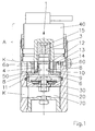
- das Bypassventil in Modulbauweise in einem axialen Längsschnitt,
- Fig.2:
- einen Schwingungsdämpfer im axialen Längsschnitt mit zwei außenadaptierten Modulen, die das Bypassventil enthalten.
- Fig.1:
- the bypass valve in modular design in an axial longitudinal section,
- Figure 2:
- a vibration damper in axial longitudinal section with two externally adapted modules containing the bypass valve.
Das in Fig. 1 gezeigte Bypassventil ist als Rucksackventil-Modul ausgebildet, welches
außen am Behälterrohr (nicht dargestellt) in an sich bekannter Weise adaptierbar
ist. Das Ventil umfasst ein Modulgehäuse 20, in welchem ein Komfortventil
30 mit Rückschlagfunktion axial und radial fixiert angeordnet ist. Dieses Komfortventil
30 wirkt in bekannter Weise als Dämpfungsventil zwischen der Zug- und
Druckstufe des (nicht dargestellten) Schwingungsdämpfers. In Fig. 1 ist vom
Komfortventil 30 aus gesehen stromabwärts ein hohlzylindrischer Führungszylinder
6 angeordnet, der ebenfalls axial und radial fixiert im Modulgehäuse 20
gehalten ist. Der Führungszylinder 6 weist an seinem dem Komfortventil 30
zugewandten Ende einen sich in radialer Richtung zum Modulgehäuse 20 hin
erstreckenden Absatz 9 auf, durch den der Führungszylinder 6 in axialer und radialer
Richtung fixiert an dem Modulgehäuse 20 gehalten ist. In die vom Komfortventil
30 wegweisende axiale Richtung erstreckt sich der hohlzylindrische Teil 6a
des Führungszylinders 6, sodass dieser hohlzylindrische Teil 6a einen Führungszapfen
bildet, auf welchem ein hohlzylindrischer Stellschieber 4 axial verschiebbar
geführt ist. In dem in Fig. 1 dargestellten Ausführungsbeispiel ist der Stellschieber
4 einstückig mit dem Schaft 3 des Ventilschiebers 1 ausgebildet.The bypass valve shown in Fig. 1 is designed as a backpack valve module, which
on the outside of the container tube (not shown) adaptable in a conventional manner
is. The valve comprises a
Im Ausführungsbeispiel bildet der Schaft 3 einen Anker, der axial beweglich innerhalb
der Spule eines stromgesteuerten Elektromagneten 40 angeordnet ist. Der
Elektromagnet 40 bildet mit dem Anker 3 einen elektromechanischen Linearantrieb,
welcher als Stellantrieb A für den Stellschieber 4 dient.In the exemplary embodiment, the
Der hohlzylindrische Stellschieber 4 ist umschlossen von einem ringförmigen
Distanzelement 13. Zwischen dem Distanzelement 13 und dem Stellschieber 4 ist
ein innerer Ringraum 14 vorhanden, welcher über in der Wand des Distanzelements
13 angeordnete Bohrungen 50 mit einem äußeren Ringraum 60 verbunden
ist. Dieser Ringraum 60 kann entweder mit dem Arbeitsraum der Zug- oder
der Druckstufe des (in Fig. 1 nicht dargestellten) Schwingungsdämpfers über eine
Koppelbohrung K verbunden sein. Mit welchem Arbeitsraum der Ringraum 60 verbunden
wird, hängt davon ab, in welcher Stufe (Zug oder Druck) das Komfortventil
30 seine Dämpfungswirkung entfalten soll.The hollow
Im Mantel des hohlzylindrischen Stellschiebers 4 sind Durchbrüche 8 vorhanden.
Der freie Querschnitt dieser Durchbrüche 8 kann durch axiale Verschiebung des
Stellschiebers 4 eingestellt werden. Wenn der Stellschieber 4 die Durchbrüche 8
vollständig freigibt, ist der äußere Ringraum 60 mit dem Raum 70 unter Zwischenschaltung
des Komfortventils 30 hydraulisch gekoppelt. In diesem Zustand wird
das Dämpfungsverhalten des Rucksackventils durch das Komfortventil 30
bestimmt. Bei dem in Fig. 1 dargestellten Ausführungsbeispiel ist der Raum 70 mit
der Druckstufe des nicht dargestellten Schwingungsdämpfers verbunden, während
der äußere Ringraum 60 mit der Zugstufe des Schwingungsdämpfers verbunden
ist. Fährt die Kolbenstange des Schwingungsdämpfers bei Belastung in den
Schwingungsdämpfer ein, so wird Dämpfungsflüssigkeit aus der Druckstufe in den
Raum 70 und von diesem über das Komfortventil 30 in das Innere des hohlzylindrischen
Führungszylinders 6 transportiert. Dabei ruft das Komfortventil 30 eine
Dämpfungskraft hervor. Aus dem Innenraum des hohlzylindrischen Führungszylinders
6 strömt die Dämpfungsflüssigkeit durch die Durchbrüche 8 in den inneren
Ringraum 14 und von diesem durch die Bohrungen 50 in den äußeren Ringraum
60, der wiederum mit der Zugstufe des Schwingungsdämpfers verbunden
ist. Dabei entfaltet der freie Querschnitt der Durchbrüche 8 eine Drosselwirkung.
Diese Drosselwirkung kann durch eine gezielte axiale Verschiebung des Stellschiebers
4, die zu einer Verringerung des freien Querschnitts der Durchbrüche 8
führt, gezielt gesteigert werden. Auf diese Weise lässt sich das Dämpfungsverhalten
des Rucksackventils kontinuierlich einstellen.In the jacket of the hollow
Die axiale Verschiebung des Stellschiebers 4 auf dem Führungszylinder 6 erfolgt
in aus dem Stand der Technik an sich bekannter Weise durch eine Veränderung
des Ansteuerstroms, mit dem der Elektromagnet 40 angesteuert wird. Die dem
Stellschieber 4 zugewandte Oberfläche des Absatzes 9 bildet eine Ventilsitzfläche
10, auf der der Stellschieber 4 mit seiner Stirnfläche dichtend aufsetzbar ist,
sodass keine Leckage vorliegt. Die Wandung des hohlzylindrischen Stellschiebers
4 weist an der der Ventilsitzfläche 10 zugewandten Stirnseite eine Fase 11 auf,
sodass die Größe der Stirnfläche des Stellschiebers 4 reduziert ist. Sie bietet
somit weniger Angriffsfläche für die in der strömenden Dämpfungsflüssigkeit auftretenden
Druckschwankungen, sodass die daraus resultierenden Störkräfte verringert
werden, die auf den Stellschieber 4 übertragen werden.The axial displacement of the adjusting
Der Vorteil bei dem in Fig. 1 dargestellten Ausführungsbeispiel des erfindungsgemäßen
Bypassventils besteht darin, dass sämtliche von der strömenden
Dämpfungsflüssigkeit ausgehenden Störkräfte nahezu vollständig von dem axial
und radial fixierten Führungszylinder 6 aufgenommen und in das Modulgehäuse
20 abgeleitet werden. Auf diese Weise wird der Stellschieber 4 von den durch die
Strömung verursachten Störkräften entkoppelt. Ebenso wird die Reibung zwischen
dem Führungszylinder 6 und dem Stellschieber 4 minimiert, sodass die axiale
Verschiebung des Stellschiebers 4 mit einer vergleichsweise geringen Kraft des
Stellantriebs A realisiert werden kann.The advantage in the embodiment of the invention shown in FIG
Bypass valve is that all of the flowing
Damping fluid emanating disturbing forces almost completely from the axial
and radially fixed
In Fig. 2 ist ein Schwingungsdämpfer dargestellt, an dessen äußerem Behälterrohr
zwei Rucksackventile adaptiert sind, welche jeweils das erfindungsgemäße
Bypassventil enthalten. Das in Fig. 2 auf der rechten Seite angeordnete Rucksackventil
entspricht dem in Fig. 1 dargestellten Rucksackventil und ist in der
Druckstufe des Schwingungsdämpfers wirksam. Das in Fig. 2 auf der linken Seite
dargestellte Rucksackventil ist dagegen in der Zugstufe des Schwingungsdämpfers
wirksam. Der Aufbau des in Fig. 2 auf der linken Seite dargestellten Rucksackventils
entspricht dem Aufbau des in Fig. 1 dargestellten Rucksackventils.
Lediglich wurde das in Fig. 2 auf der linken Seite dargestellte Rucksackventil um
180° verdreht zum auf der rechten Seite dargestellten Rucksackventil montiert.
Auf diese Weise wird erreicht, dass das Komfortventil 30 in der umgekehrten
Strömungsrichtung des Dämpfungsmediums wirksam ist, als dies bei dem anderen
Rucksackventil der Fall ist.In Fig. 2, a vibration damper is shown, on the outer container tube
two backpack valves are adapted, which in each case the inventive
Bypass valve included. The arranged in Fig. 2 on the right side backpack valve
corresponds to the backpack valve shown in Fig. 1 and is in the
Pressure stage of the vibration damper effective. That in Fig. 2 on the left side
illustrated backpack valve, however, is in the rebound of the vibration
effective. The structure of the backpack valve shown in Fig. 2 on the left side
corresponds to the structure of the backpack valve shown in Fig. 1.
Only the backpack valve shown in Fig. 2 on the left side was around
180 ° twisted to the backpack valve shown on the right.
In this way it is achieved that the
Bei dem in Fig. 2 dargestellten Schwingungsdämpfer ist es möglich, das Dämpfungsverhalten in der Zug- bzw. Druckstufe unabhängig voneinander unterschiedlich einzustellen. Dadurch wird die Voraussetzung für eine nach dem Skyhook-Prinzip arbeitende Fahrzeugdämpfung geschaffen. Anstatt das komplette Modul um 180° zu drehen ist es auch möglich, nur das Komfortventil zu drehen. In the vibration damper shown in Fig. 2, it is possible, the damping behavior different in the tension or compression independently adjust. This will be the prerequisite for a Skyhook principle working vehicle damping created. Instead of the complete module It is also possible to turn only the comfort valve to turn 180 °.
- 11
- Ventilschiebervalve slide
- 33
- Schaftshaft
- 44
- Stellschieberlock slider
- 66
- Führungskörperguide body
- 6a6a
- hohlzylindrischer Teilhollow cylindrical part
- 88th
- Durchbruchbreakthrough
- 99
- Absatzparagraph
- 1010
- VentilsitzflächeValve seat
- 1111
- Fasechamfer
- 1212
- Entlastungsnutrelief
- 1313
- Distanzelementspacer
- 1414
- innerer Ringrauminner annulus
- 1515
- DruckentlastungsbohrungPressure relief hole
- 2020
- Modulgehäusemodule housing
- 3030
- Komfortventilcomfort valve
- 4040
- Elektromagnetelectromagnet
- 5050
- Bohrungdrilling
- 6060
- äußerer Ringraumouter annulus
- 7070
- Raumroom
- AA
- Stellantriebactuator
- KK
- Koppelbohrungcoupling hole
Claims (11)
Applications Claiming Priority (2)
| Application Number | Priority Date | Filing Date | Title |
|---|---|---|---|
| DE10357020 | 2003-12-05 | ||
| DE10357020 | 2003-12-05 |
Publications (2)
| Publication Number | Publication Date |
|---|---|
| EP1538366A1 true EP1538366A1 (en) | 2005-06-08 |
| EP1538366B1 EP1538366B1 (en) | 2006-02-08 |
Family
ID=34442475
Family Applications (1)
| Application Number | Title | Priority Date | Filing Date |
|---|---|---|---|
| EP04026369A Active EP1538366B1 (en) | 2003-12-05 | 2004-11-05 | Bypass valve for damper |
Country Status (5)
| Country | Link |
|---|---|
| US (1) | US20050121273A1 (en) |
| EP (1) | EP1538366B1 (en) |
| AT (1) | ATE317512T1 (en) |
| DE (1) | DE502004000281D1 (en) |
| ES (1) | ES2253723T3 (en) |
Cited By (7)
| Publication number | Priority date | Publication date | Assignee | Title |
|---|---|---|---|---|
| EP2103834A2 (en) | 2008-03-20 | 2009-09-23 | ThyssenKrupp Bilstein Suspension GmbH | Damping valve for a hydraulic vibration damper |
| DE102008015415A1 (en) | 2008-03-20 | 2009-10-01 | Thyssenkrupp Bilstein Suspension Gmbh | Damping valve for a hydraulic vibration damper |
| DE102008015412A1 (en) | 2008-03-20 | 2009-10-08 | Thyssenkrupp Bilstein Suspension Gmbh | Vibration damper with backpack valve |
| DE102015112180A1 (en) * | 2015-07-27 | 2017-02-02 | Thyssenkrupp Ag | Vibration damper for a motor vehicle |
| WO2017137189A1 (en) * | 2016-02-12 | 2017-08-17 | Zf Friedrichshafen Ag | Vibration damper assembly and motor vehicle |
| EP3409984A1 (en) | 2017-05-30 | 2018-12-05 | Rausch und Pausch GmbH | Piston slide valve |
| DE102018107763A1 (en) | 2018-04-03 | 2019-10-10 | Rausch & Pausch Gmbh | MAGNETIC VALVE |
Families Citing this family (5)
| Publication number | Priority date | Publication date | Assignee | Title |
|---|---|---|---|---|
| US7946163B2 (en) | 2007-04-02 | 2011-05-24 | Penske Racing Shocks | Methods and apparatus for developing a vehicle suspension |
| DE102014225702A1 (en) * | 2014-12-12 | 2016-06-16 | Zf Friedrichshafen Ag | Adjustable damper valve device |
| DE102017210308A1 (en) | 2017-06-20 | 2018-12-20 | Thyssenkrupp Ag | car assembly |
| DE102018132174A1 (en) * | 2018-12-13 | 2020-06-18 | Thyssenkrupp Ag | Adjustable vibration damper and motor vehicle with such a vibration damper |
| US11906015B2 (en) | 2022-01-03 | 2024-02-20 | DRiV Automotive Inc. | Damper with a slanted elliptical seal between an intermediate tube and an inner pressure tube |
Citations (5)
| Publication number | Priority date | Publication date | Assignee | Title |
|---|---|---|---|---|
| DE3530395A1 (en) * | 1985-08-24 | 1987-02-26 | Fichtel & Sachs Ag | Oscillation damper for vehicles |
| EP0355357A2 (en) * | 1988-08-13 | 1990-02-28 | Robert Bosch Gmbh | Apparatus for damping sprung wheel suspension systems |
| DE4011358C1 (en) * | 1990-04-07 | 1991-08-22 | August Bilstein Gmbh & Co. Kg, 5828 Ennepetal, De | |
| WO1996015390A1 (en) * | 1994-11-14 | 1996-05-23 | Industrieanlagen-Betriebsgesellschaft Mbh | Vibration damper, in particular for vehicles |
| DE19938699A1 (en) * | 1998-09-17 | 2000-03-23 | Stabilus Gmbh | Valve holds door in pre-chosen position and system allows adaptation of valve to specific requirement |
Family Cites Families (12)
| Publication number | Priority date | Publication date | Assignee | Title |
|---|---|---|---|---|
| US4785920A (en) * | 1986-04-16 | 1988-11-22 | Boge Ag | Hydraulic adjustable shock absorber |
| US5011113A (en) * | 1988-12-29 | 1991-04-30 | Applied Power Inc. | Fluid control valve |
| US5005803A (en) * | 1988-12-29 | 1991-04-09 | Applied Power Inc. | High response, compact solenoid two-way valve |
| DE4024920C2 (en) * | 1990-08-06 | 1996-02-01 | Fichtel & Sachs Ag | Vibration damper |
| DE4105771A1 (en) * | 1991-02-23 | 1992-08-27 | Boge Ag | Hydraulic adjustable vibration damper for vehicle - involves controlling pressure forces in damping valve |
| DE4132262A1 (en) * | 1991-09-27 | 1993-04-01 | Teves Gmbh Alfred | HYDRAULIC VIBRATION DAMPER FOR MOTOR VEHICLES |
| DE4213803A1 (en) * | 1992-04-27 | 1993-10-28 | Teves Gmbh Alfred | Pilot operated valve for chassis control systems |
| US5651433A (en) * | 1992-07-15 | 1997-07-29 | Fichtel & Sachs Ag | Fluid operated oscillation damper |
| GB2276435B (en) * | 1993-03-16 | 1997-01-15 | Fichtel & Sachs Ag | Vibration damper |
| DE4424436C2 (en) * | 1994-07-12 | 1997-11-27 | Mannesmann Sachs Ag | Shut-off valve assembly for a vibration damper |
| JP3887760B2 (en) * | 1996-08-09 | 2007-02-28 | 株式会社日立製作所 | Damping force adjustable hydraulic shock absorber |
| DE19953372A1 (en) * | 1999-02-10 | 2000-08-17 | Sachs Race Eng Gmbh | Variable damper with adjustable damping force has damping valve housing closed off at one end by a cover which has a device for engagement with the external adjusting unit |
-
2004
- 2004-11-05 ES ES04026369T patent/ES2253723T3/en active Active
- 2004-11-05 AT AT04026369T patent/ATE317512T1/en not_active IP Right Cessation
- 2004-11-05 EP EP04026369A patent/EP1538366B1/en active Active
- 2004-11-05 DE DE502004000281T patent/DE502004000281D1/en active Active
- 2004-11-29 US US10/998,876 patent/US20050121273A1/en not_active Abandoned
Patent Citations (5)
| Publication number | Priority date | Publication date | Assignee | Title |
|---|---|---|---|---|
| DE3530395A1 (en) * | 1985-08-24 | 1987-02-26 | Fichtel & Sachs Ag | Oscillation damper for vehicles |
| EP0355357A2 (en) * | 1988-08-13 | 1990-02-28 | Robert Bosch Gmbh | Apparatus for damping sprung wheel suspension systems |
| DE4011358C1 (en) * | 1990-04-07 | 1991-08-22 | August Bilstein Gmbh & Co. Kg, 5828 Ennepetal, De | |
| WO1996015390A1 (en) * | 1994-11-14 | 1996-05-23 | Industrieanlagen-Betriebsgesellschaft Mbh | Vibration damper, in particular for vehicles |
| DE19938699A1 (en) * | 1998-09-17 | 2000-03-23 | Stabilus Gmbh | Valve holds door in pre-chosen position and system allows adaptation of valve to specific requirement |
Cited By (18)
| Publication number | Priority date | Publication date | Assignee | Title |
|---|---|---|---|---|
| DE102008015416B4 (en) * | 2008-03-20 | 2012-10-11 | Thyssenkrupp Bilstein Suspension Gmbh | Damping valve for a hydraulic vibration damper |
| DE102008015415A1 (en) | 2008-03-20 | 2009-10-01 | Thyssenkrupp Bilstein Suspension Gmbh | Damping valve for a hydraulic vibration damper |
| DE102008015412B4 (en) * | 2008-03-20 | 2013-08-22 | Thyssenkrupp Bilstein Suspension Gmbh | Vibration damper with backpack valve |
| US8613348B2 (en) | 2008-03-20 | 2013-12-24 | Thyssenkrupp Bilstein Suspension Gmbh | Oscillation damper having a backpack valve |
| EP2108857A2 (en) | 2008-03-20 | 2009-10-14 | ThyssenKrupp Bilstein Suspension GmbH | Damping valve for a hydraulic vibration damper |
| EP2108857A3 (en) * | 2008-03-20 | 2011-11-30 | ThyssenKrupp Bilstein Suspension GmbH | Damping valve for a hydraulic vibration damper |
| EP2103834A3 (en) * | 2008-03-20 | 2011-11-30 | ThyssenKrupp Bilstein Suspension GmbH | Damping valve for a hydraulic vibration damper |
| DE102008015415B4 (en) * | 2008-03-20 | 2012-08-23 | Thyssenkrupp Bilstein Suspension Gmbh | Damping valve for a hydraulic vibration damper |
| EP2103834A2 (en) | 2008-03-20 | 2009-09-23 | ThyssenKrupp Bilstein Suspension GmbH | Damping valve for a hydraulic vibration damper |
| DE102008015416A1 (en) | 2008-03-20 | 2009-10-01 | Thyssenkrupp Bilstein Suspension Gmbh | Damping valve for a hydraulic vibration damper |
| DE102008015412A1 (en) | 2008-03-20 | 2009-10-08 | Thyssenkrupp Bilstein Suspension Gmbh | Vibration damper with backpack valve |
| DE102015112180A1 (en) * | 2015-07-27 | 2017-02-02 | Thyssenkrupp Ag | Vibration damper for a motor vehicle |
| US10487902B2 (en) | 2015-07-27 | 2019-11-26 | Thyssenkrupp Bilstein Gmbh | Vibration damper for a motor vehicle |
| WO2017137189A1 (en) * | 2016-02-12 | 2017-08-17 | Zf Friedrichshafen Ag | Vibration damper assembly and motor vehicle |
| EP3409984A1 (en) | 2017-05-30 | 2018-12-05 | Rausch und Pausch GmbH | Piston slide valve |
| DE102017111726A1 (en) | 2017-05-30 | 2018-12-06 | Rausch & Pausch Gmbh | Piston valve |
| US10527120B2 (en) | 2017-05-30 | 2020-01-07 | Rausch & Pausch Gmbh | Piston slide valve |
| DE102018107763A1 (en) | 2018-04-03 | 2019-10-10 | Rausch & Pausch Gmbh | MAGNETIC VALVE |
Also Published As
| Publication number | Publication date |
|---|---|
| ES2253723T3 (en) | 2006-06-01 |
| US20050121273A1 (en) | 2005-06-09 |
| DE502004000281D1 (en) | 2006-04-20 |
| ATE317512T1 (en) | 2006-02-15 |
| EP1538366B1 (en) | 2006-02-08 |
Similar Documents
| Publication | Publication Date | Title |
|---|---|---|
| DE19734522C2 (en) | Hydraulic shock absorber with adjustable damping force | |
| DE3523628C2 (en) | ||
| DE3446133C2 (en) | ||
| DE3434877C2 (en) | ||
| EP2470809B1 (en) | Motor vehicle shock absorber | |
| EP0602121B1 (en) | Controllable valve arrangement for adjustable double-tube dashpots | |
| EP0400395B1 (en) | Shock absorber | |
| EP2255103B1 (en) | Oscillation damper having backpack valve | |
| EP1215413B1 (en) | Controllable vibration damper comprising a damping force adjusting device | |
| DE10126555C2 (en) | Damping force regulating hydraulic shock absorber | |
| DE10257872B4 (en) | Hydraulic shock absorber with damping force control | |
| EP0364757B1 (en) | Shock absorber for damping movements | |
| EP2236853B1 (en) | Adjustable steam valve device | |
| DE19711293C2 (en) | Hydraulic vibration damper with adjustable damping force | |
| DE3532633C2 (en) | Hydraulic damper | |
| DE4406918A1 (en) | Damping valve device | |
| DE19914504A1 (en) | Hydraulic vibration damper with adjustable damping force | |
| EP0534075A1 (en) | Damping force regulation device for shock absorber | |
| EP0405123A2 (en) | Two-way solenoid valve for bypass control | |
| EP1538366B1 (en) | Bypass valve for damper | |
| EP2243979B1 (en) | Adjustable vibration absorber with an emergency valve | |
| EP1500845B1 (en) | Shock absorber with variable damping characteristics | |
| DE19963415A1 (en) | Damping force regulating type hydraulic shock absorber | |
| EP0836982A2 (en) | Damper valve | |
| EP0599045A2 (en) | Controllable hydraulic shock absorber |
Legal Events
| Date | Code | Title | Description |
|---|---|---|---|
| PUAI | Public reference made under article 153(3) epc to a published international application that has entered the european phase |
Free format text: ORIGINAL CODE: 0009012 |
|
| 17P | Request for examination filed |
Effective date: 20050317 |
|
| AK | Designated contracting states |
Kind code of ref document: A1 Designated state(s): AT BE BG CH CY CZ DE DK EE ES FI FR GB GR HU IE IS IT LI LU MC NL PL PT RO SE SI SK TR |
|
| AX | Request for extension of the european patent |
Extension state: AL HR LT LV MK YU |
|
| GRAP | Despatch of communication of intention to grant a patent |
Free format text: ORIGINAL CODE: EPIDOSNIGR1 |
|
| GRAS | Grant fee paid |
Free format text: ORIGINAL CODE: EPIDOSNIGR3 |
|
| GRAA | (expected) grant |
Free format text: ORIGINAL CODE: 0009210 |
|
| AK | Designated contracting states |
Kind code of ref document: B1 Designated state(s): AT BE BG CH CY CZ DE DK EE ES FI FR GB GR HU IE IS IT LI LU MC NL PL PT RO SE SI SK TR |
|
| AX | Request for extension of the european patent |
Extension state: AL HR LT LV MK YU |
|
| PG25 | Lapsed in a contracting state [announced via postgrant information from national office to epo] |
Ref country code: FI Free format text: LAPSE BECAUSE OF FAILURE TO SUBMIT A TRANSLATION OF THE DESCRIPTION OR TO PAY THE FEE WITHIN THE PRESCRIBED TIME-LIMIT Effective date: 20060208 Ref country code: SI Free format text: LAPSE BECAUSE OF FAILURE TO SUBMIT A TRANSLATION OF THE DESCRIPTION OR TO PAY THE FEE WITHIN THE PRESCRIBED TIME-LIMIT Effective date: 20060208 Ref country code: NL Free format text: LAPSE BECAUSE OF FAILURE TO SUBMIT A TRANSLATION OF THE DESCRIPTION OR TO PAY THE FEE WITHIN THE PRESCRIBED TIME-LIMIT Effective date: 20060208 Ref country code: SK Free format text: LAPSE BECAUSE OF FAILURE TO SUBMIT A TRANSLATION OF THE DESCRIPTION OR TO PAY THE FEE WITHIN THE PRESCRIBED TIME-LIMIT Effective date: 20060208 Ref country code: RO Free format text: LAPSE BECAUSE OF FAILURE TO SUBMIT A TRANSLATION OF THE DESCRIPTION OR TO PAY THE FEE WITHIN THE PRESCRIBED TIME-LIMIT Effective date: 20060208 Ref country code: IE Free format text: LAPSE BECAUSE OF FAILURE TO SUBMIT A TRANSLATION OF THE DESCRIPTION OR TO PAY THE FEE WITHIN THE PRESCRIBED TIME-LIMIT Effective date: 20060208 Ref country code: PL Free format text: LAPSE BECAUSE OF FAILURE TO SUBMIT A TRANSLATION OF THE DESCRIPTION OR TO PAY THE FEE WITHIN THE PRESCRIBED TIME-LIMIT Effective date: 20060208 Ref country code: IT Free format text: LAPSE BECAUSE OF FAILURE TO SUBMIT A TRANSLATION OF THE DESCRIPTION OR TO PAY THE FEE WITHIN THE PRESCRIBED TIME-LIMIT;WARNING: LAPSES OF ITALIAN PATENTS WITH EFFECTIVE DATE BEFORE 2007 MAY HAVE OCCURRED AT ANY TIME BEFORE 2007. THE CORRECT EFFECTIVE DATE MAY BE DIFFERENT FROM THE ONE RECORDED. Effective date: 20060208 |
|
| REG | Reference to a national code |
Ref country code: GB Ref legal event code: FG4D Free format text: NOT ENGLISH |
|
| REG | Reference to a national code |
Ref country code: CH Ref legal event code: EP |
|
| AKX | Designation fees paid |
Designated state(s): AT BE BG CH CY CZ DE DK EE ES FI FR GB GR HU IE IS IT LI LU MC NL PL PT RO SE SI SK TR |
|
| AXX | Extension fees paid |
Extension state: MK Payment date: 20051208 Extension state: LV Payment date: 20051208 Extension state: LT Payment date: 20051208 Extension state: HR Payment date: 20051208 Extension state: YU Payment date: 20051208 Extension state: AL Payment date: 20051208 |
|
| GBT | Gb: translation of ep patent filed (gb section 77(6)(a)/1977) |
Effective date: 20060208 |
|
| REG | Reference to a national code |
Ref country code: IE Ref legal event code: FG4D Free format text: LANGUAGE OF EP DOCUMENT: GERMAN |
|
| RAP2 | Party data changed (patent owner data changed or rights of a patent transferred) |
Owner name: THYSSENKRUPP BILSTEIN SUSPENSION GMBH |
|
| REF | Corresponds to: |
Ref document number: 502004000281 Country of ref document: DE Date of ref document: 20060420 Kind code of ref document: P |
|
| PG25 | Lapsed in a contracting state [announced via postgrant information from national office to epo] |
Ref country code: BG Free format text: LAPSE BECAUSE OF FAILURE TO SUBMIT A TRANSLATION OF THE DESCRIPTION OR TO PAY THE FEE WITHIN THE PRESCRIBED TIME-LIMIT Effective date: 20060508 Ref country code: DK Free format text: LAPSE BECAUSE OF FAILURE TO SUBMIT A TRANSLATION OF THE DESCRIPTION OR TO PAY THE FEE WITHIN THE PRESCRIBED TIME-LIMIT Effective date: 20060508 |
|
| REG | Reference to a national code |
Ref country code: SE Ref legal event code: TRGR |
|
| REG | Reference to a national code |
Ref country code: ES Ref legal event code: FG2A Ref document number: 2253723 Country of ref document: ES Kind code of ref document: T3 |
|
| NLT2 | Nl: modifications (of names), taken from the european patent patent bulletin |
Owner name: THYSSENKRUPP BILSTEIN SUSPENSION GMBH Effective date: 20060419 |
|
| NLV1 | Nl: lapsed or annulled due to failure to fulfill the requirements of art. 29p and 29m of the patents act | ||
| ET | Fr: translation filed | ||
| PG25 | Lapsed in a contracting state [announced via postgrant information from national office to epo] |
Ref country code: PT Free format text: LAPSE BECAUSE OF FAILURE TO SUBMIT A TRANSLATION OF THE DESCRIPTION OR TO PAY THE FEE WITHIN THE PRESCRIBED TIME-LIMIT Effective date: 20060710 |
|
| LTIE | Lt: invalidation of european patent or patent extension |
Effective date: 20060208 |
|
| REG | Reference to a national code |
Ref country code: IE Ref legal event code: FD4D |
|
| PG25 | Lapsed in a contracting state [announced via postgrant information from national office to epo] |
Ref country code: BE Free format text: LAPSE BECAUSE OF NON-PAYMENT OF DUE FEES Effective date: 20061130 Ref country code: MC Free format text: LAPSE BECAUSE OF NON-PAYMENT OF DUE FEES Effective date: 20061130 |
|
| PLBE | No opposition filed within time limit |
Free format text: ORIGINAL CODE: 0009261 |
|
| STAA | Information on the status of an ep patent application or granted ep patent |
Free format text: STATUS: NO OPPOSITION FILED WITHIN TIME LIMIT |
|
| 26N | No opposition filed |
Effective date: 20061109 |
|
| BERE | Be: lapsed |
Owner name: THYSSENKRUPP BILSTEIN G.M.B.H. Effective date: 20061130 |
|
| PG25 | Lapsed in a contracting state [announced via postgrant information from national office to epo] |
Ref country code: AT Free format text: LAPSE BECAUSE OF NON-PAYMENT OF DUE FEES Effective date: 20061105 |
|
| PG25 | Lapsed in a contracting state [announced via postgrant information from national office to epo] |
Ref country code: GR Free format text: LAPSE BECAUSE OF FAILURE TO SUBMIT A TRANSLATION OF THE DESCRIPTION OR TO PAY THE FEE WITHIN THE PRESCRIBED TIME-LIMIT Effective date: 20060509 Ref country code: CZ Free format text: LAPSE BECAUSE OF FAILURE TO SUBMIT A TRANSLATION OF THE DESCRIPTION OR TO PAY THE FEE WITHIN THE PRESCRIBED TIME-LIMIT Effective date: 20060208 |
|
| PG25 | Lapsed in a contracting state [announced via postgrant information from national office to epo] |
Ref country code: EE Free format text: LAPSE BECAUSE OF FAILURE TO SUBMIT A TRANSLATION OF THE DESCRIPTION OR TO PAY THE FEE WITHIN THE PRESCRIBED TIME-LIMIT Effective date: 20060208 |
|
| PG25 | Lapsed in a contracting state [announced via postgrant information from national office to epo] |
Ref country code: TR Free format text: LAPSE BECAUSE OF FAILURE TO SUBMIT A TRANSLATION OF THE DESCRIPTION OR TO PAY THE FEE WITHIN THE PRESCRIBED TIME-LIMIT Effective date: 20060208 Ref country code: LU Free format text: LAPSE BECAUSE OF NON-PAYMENT OF DUE FEES Effective date: 20061105 Ref country code: IS Free format text: LAPSE BECAUSE OF FAILURE TO SUBMIT A TRANSLATION OF THE DESCRIPTION OR TO PAY THE FEE WITHIN THE PRESCRIBED TIME-LIMIT Effective date: 20060208 Ref country code: HU Free format text: LAPSE BECAUSE OF FAILURE TO SUBMIT A TRANSLATION OF THE DESCRIPTION OR TO PAY THE FEE WITHIN THE PRESCRIBED TIME-LIMIT Effective date: 20060809 |
|
| PG25 | Lapsed in a contracting state [announced via postgrant information from national office to epo] |
Ref country code: CY Free format text: LAPSE BECAUSE OF FAILURE TO SUBMIT A TRANSLATION OF THE DESCRIPTION OR TO PAY THE FEE WITHIN THE PRESCRIBED TIME-LIMIT Effective date: 20060208 |
|
| REG | Reference to a national code |
Ref country code: CH Ref legal event code: PL |
|
| PG25 | Lapsed in a contracting state [announced via postgrant information from national office to epo] |
Ref country code: LI Free format text: LAPSE BECAUSE OF NON-PAYMENT OF DUE FEES Effective date: 20081130 Ref country code: CH Free format text: LAPSE BECAUSE OF NON-PAYMENT OF DUE FEES Effective date: 20081130 |
|
| REG | Reference to a national code |
Ref country code: FR Ref legal event code: PLFP Year of fee payment: 12 |
|
| REG | Reference to a national code |
Ref country code: FR Ref legal event code: PLFP Year of fee payment: 13 |
|
| REG | Reference to a national code |
Ref country code: FR Ref legal event code: PLFP Year of fee payment: 14 |
|
| PGFP | Annual fee paid to national office [announced via postgrant information from national office to epo] |
Ref country code: ES Payment date: 20230630 Year of fee payment: 19 |
|
| PGFP | Annual fee paid to national office [announced via postgrant information from national office to epo] |
Ref country code: GB Payment date: 20231123 Year of fee payment: 20 |
|
| PGFP | Annual fee paid to national office [announced via postgrant information from national office to epo] |
Ref country code: SE Payment date: 20231120 Year of fee payment: 20 Ref country code: IT Payment date: 20231124 Year of fee payment: 20 Ref country code: FR Payment date: 20231120 Year of fee payment: 20 Ref country code: DE Payment date: 20231121 Year of fee payment: 20 |
|
| PGFP | Annual fee paid to national office [announced via postgrant information from national office to epo] |
Ref country code: ES Payment date: 20240124 Year of fee payment: 20 |