EP1538330B1 - Selbstentlüftendes Kraftstoffversorgungssystem für einen Dieselmotor mit einer durch Schwerkraft erstbefüllten Förderpumpe - Google Patents
Selbstentlüftendes Kraftstoffversorgungssystem für einen Dieselmotor mit einer durch Schwerkraft erstbefüllten Förderpumpe Download PDFInfo
- Publication number
- EP1538330B1 EP1538330B1 EP03022606A EP03022606A EP1538330B1 EP 1538330 B1 EP1538330 B1 EP 1538330B1 EP 03022606 A EP03022606 A EP 03022606A EP 03022606 A EP03022606 A EP 03022606A EP 1538330 B1 EP1538330 B1 EP 1538330B1
- Authority
- EP
- European Patent Office
- Prior art keywords
- fuel
- feed pump
- pump
- supply system
- injection pump
- Prior art date
- Legal status (The legal status is an assumption and is not a legal conclusion. Google has not performed a legal analysis and makes no representation as to the accuracy of the status listed.)
- Expired - Lifetime
Links
- 239000000446 fuel Substances 0.000 title claims abstract description 142
- 230000005484 gravity Effects 0.000 title description 5
- 239000002828 fuel tank Substances 0.000 claims abstract description 25
- 238000002347 injection Methods 0.000 claims abstract description 23
- 239000007924 injection Substances 0.000 claims abstract description 23
- 230000037452 priming Effects 0.000 claims description 11
- 241000538562 Banjos Species 0.000 claims description 4
- 238000011144 upstream manufacturing Methods 0.000 claims description 2
- 238000013022 venting Methods 0.000 claims 2
- 230000002706 hydrostatic effect Effects 0.000 claims 1
- 230000001105 regulatory effect Effects 0.000 claims 1
- 230000000740 bleeding effect Effects 0.000 description 6
- 230000001419 dependent effect Effects 0.000 description 1
- 238000011161 development Methods 0.000 description 1
- 230000018109 developmental process Effects 0.000 description 1
- 239000002283 diesel fuel Substances 0.000 description 1
- 235000003642 hunger Nutrition 0.000 description 1
- 238000012423 maintenance Methods 0.000 description 1
- 238000000034 method Methods 0.000 description 1
- 238000012986 modification Methods 0.000 description 1
- 230000004048 modification Effects 0.000 description 1
- 239000011148 porous material Substances 0.000 description 1
Images
Classifications
-
- F—MECHANICAL ENGINEERING; LIGHTING; HEATING; WEAPONS; BLASTING
- F02—COMBUSTION ENGINES; HOT-GAS OR COMBUSTION-PRODUCT ENGINE PLANTS
- F02M—SUPPLYING COMBUSTION ENGINES IN GENERAL WITH COMBUSTIBLE MIXTURES OR CONSTITUENTS THEREOF
- F02M55/00—Fuel-injection apparatus characterised by their fuel conduits or their venting means; Arrangements of conduits between fuel tank and pump F02M37/00
-
- F—MECHANICAL ENGINEERING; LIGHTING; HEATING; WEAPONS; BLASTING
- F02—COMBUSTION ENGINES; HOT-GAS OR COMBUSTION-PRODUCT ENGINE PLANTS
- F02M—SUPPLYING COMBUSTION ENGINES IN GENERAL WITH COMBUSTIBLE MIXTURES OR CONSTITUENTS THEREOF
- F02M37/00—Apparatus or systems for feeding liquid fuel from storage containers to carburettors or fuel-injection apparatus; Arrangements for purifying liquid fuel specially adapted for, or arranged on, internal-combustion engines
- F02M37/20—Apparatus or systems for feeding liquid fuel from storage containers to carburettors or fuel-injection apparatus; Arrangements for purifying liquid fuel specially adapted for, or arranged on, internal-combustion engines characterised by means for preventing vapour lock
-
- F—MECHANICAL ENGINEERING; LIGHTING; HEATING; WEAPONS; BLASTING
- F02—COMBUSTION ENGINES; HOT-GAS OR COMBUSTION-PRODUCT ENGINE PLANTS
- F02M—SUPPLYING COMBUSTION ENGINES IN GENERAL WITH COMBUSTIBLE MIXTURES OR CONSTITUENTS THEREOF
- F02M59/00—Pumps specially adapted for fuel-injection and not provided for in groups F02M39/00 -F02M57/00, e.g. rotary cylinder-block type of pumps
- F02M59/02—Pumps specially adapted for fuel-injection and not provided for in groups F02M39/00 -F02M57/00, e.g. rotary cylinder-block type of pumps of reciprocating-piston or reciprocating-cylinder type
- F02M59/04—Pumps specially adapted for fuel-injection and not provided for in groups F02M39/00 -F02M57/00, e.g. rotary cylinder-block type of pumps of reciprocating-piston or reciprocating-cylinder type characterised by special arrangement of cylinders with respect to piston-driving shaft, e.g. arranged parallel to that shaft or swash-plate type pumps
-
- F—MECHANICAL ENGINEERING; LIGHTING; HEATING; WEAPONS; BLASTING
- F02—COMBUSTION ENGINES; HOT-GAS OR COMBUSTION-PRODUCT ENGINE PLANTS
- F02M—SUPPLYING COMBUSTION ENGINES IN GENERAL WITH COMBUSTIBLE MIXTURES OR CONSTITUENTS THEREOF
- F02M59/00—Pumps specially adapted for fuel-injection and not provided for in groups F02M39/00 -F02M57/00, e.g. rotary cylinder-block type of pumps
- F02M59/44—Details, components parts, or accessories not provided for in, or of interest apart from, the apparatus of groups F02M59/02 - F02M59/42; Pumps having transducers, e.g. to measure displacement of pump rack or piston
-
- F—MECHANICAL ENGINEERING; LIGHTING; HEATING; WEAPONS; BLASTING
- F02—COMBUSTION ENGINES; HOT-GAS OR COMBUSTION-PRODUCT ENGINE PLANTS
- F02B—INTERNAL-COMBUSTION PISTON ENGINES; COMBUSTION ENGINES IN GENERAL
- F02B3/00—Engines characterised by air compression and subsequent fuel addition
- F02B3/06—Engines characterised by air compression and subsequent fuel addition with compression ignition
Definitions
- the present invention is directed to a fuel supply system for a diesel engine according to the preamble portion of claim 1.
- a corresponding fuel supply system for a diesel engine is disclosed in US-4,984,554 .
- This U.S. patent discloses an Automatic air bleeding device for fuel feed system of diesel engine.
- the said device is fitted in a fuel supply system, which has a check valve disposed in a suction-side line of a feed pump.
- the said check valve is a directional valve, which permits the fuel to direct only towards a feed pump.
- a bypass line is provided for bypassing the check valve; and an electrical pump is disposed in the bypass line.
- the said pump is connected parallel with the fuel feed pump, upstream of the check valve.
- the air removal and priming is typically done manually.
- operator has to disconnect the fuel pipe connections manually and pump the manual fuel feed pump (which is sometimes called as priming pump) in order to prime the fuel feed pump and remove the entrapped air from the fuel supply system.
- priming pump the manual fuel feed pump
- US-5,899,193 discloses a fuel system & method for priming a diesel engine fuel system after assembly or when run out of fuel.
- the said system comprises a fuel tank enclosing a fuel feed pump with an outlet in an upper portion of the tank.
- the said system is provided with a fuel priming connection to the injection pump inlet.
- the connection has a closure for shutting the connection when not in use by means of a mechanically openable check valve, such as Schraeder valve.
- This valve is like the mechanically actuated type used in vehicle tyres to allow their inflation and prevent the escape of air unless actuated to an open position.
- diesel fuel is delivered through the said check valve in the fuel supply system. This fuel flows back to the fuel tank through the filters, allowing to escape the trapped air from the system.
- the engine then may be started with minimum cranking.
- the engine may be restarted by partially filling the tank and manually opening the said check valve.
- the feed pump is operated which forces the fuel to bleed air from system through this valve, which is closed prior to engine starting.
- the engine may then reprimed after shutdown if required.
- the said system involves manual operation.
- the feed pump enclosed in the fuel tank is difficult to access while carrying out maintenance.
- the said system may not work.
- the fuel may not flow through the minute pores of the filter by gravity. Therefore priming of the Fuel injection pump is not possible. Also, In case of clogging of the fuel filter, it will be difficult for fuel injection pump to suck the fuel from the Fuel filter.
- Some manufacturers provide by-pass lines from fuel filter & fuel injection pump to remove entrapped air from system to the fuel tank. But the fuel feed pump can not be primed automatically, as there is a restriction of fuel filter before the fuel feed pump.
- this object is performed by fuel supply system according to claim 1.
- the fuel supply system according to the invention eliminates the manual operations involved in priming the fuel feed pump and bleeding the air from the system.
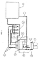
- Fig. 1 shows the fuel supply system for diesel engine in accordance with the invention.
- the system includes fuel tank 1 which acts as reservoir of fuel for fuel supply system.
- Fuel pipe 2 takes the fuel from fuel tank to fuel feed pump 3, which is mounted below the level of fuel tank.
- This specific arrangement of the fuel feed pump below the level of fuel tank enables free flow of fuel to fuel feed pump 3 by gravity hence automatically priming the fuel feed pump.
- the care has been taken to avoid any restriction between fuel tank 1 and fuel feed pump 3.
- fuel filter is mounted between the fuel tank & fuel feed pump, which does not allow free flow of fuel to the fuel fed pump by gravity.
- Fuel pipe 4 takes pressurized fuel from fuel feed pump to fuel filter 5.
- Fuel pipe 6 takes fuel from fuel filter 5 to fuel injection pump 8.
- a banjo bolt 7 facilitates the connection of fuel pipe 6 to fuel injection pump 8.
- Fuel injection pump 8 feeds fuel to engine via injectors 10 at a predetermined pressure.
- Fuel pipe 9 takes fuel from fuel injection pump 8 to the injectors 10.
- a banjo bolt 11 is also fitted on the fuel injection pump 8. This banjo bolt contains a pressure-regulating valve within it, which maintains a predefined pressure in the fuel injection pump 8. When the pressure in the fuel injection pump 8 goes higher than the predefined value the said valve opens against a spring and allows the extra fuel to pass to the fuel tank through the return line 12.
- the advantage of the fuel filter 5 after the fuel feed pump 3 is that it will minimize the chances of starving of engine for fuel in case of filter clogging, as fuel feed pump will always try to force the fuel through the filters.
- the fuel feed pump 3 After refueling the fuel from the fuel tank flows to the fuel feed pump 3 by gravity and primes it. As operator cranks the engine by turning the starting key, the fuel feed pump pressurizes the fuel & forces it through the entire system. The pressurized fuel forces the entrapped air in the system to the fuel injection pump 8.
- the micro-hole provided on the valve seat allows this entrapped air to escape through the return line 12 and hence facilitates automatic self air bleeding.
- the present invention is not limited to the system described above and various modifications can be done without affecting the basic concept explained here.
- the micro-hole provided on the valve seat is for the purpose of removal of air from the pressure side of the system without allowing the fuel to pass through it (because of very small hole size).
- This kind of hole can be provided anywhere on the pressure side of the fuel supply system.
Landscapes
- Engineering & Computer Science (AREA)
- Chemical & Material Sciences (AREA)
- Combustion & Propulsion (AREA)
- Mechanical Engineering (AREA)
- General Engineering & Computer Science (AREA)
- Fuel-Injection Apparatus (AREA)
Claims (4)
- Kraftstoffversorgungssystem, umfassend:- einen Kraftstofftank (1);- eine Kraftstoffförderpumpe (3) zum Fördern von Kraftstoff von dem Kraftstofftank (1),- eine Kraftstoffeinspritzpumpe (8),- Injektoren (10), die der Kraftstoffeinspritzpumpe (8) Kraftstoff entnehmen, und- einen Kraftstofffilter (5), der den Filterungsgrad des der Einspritzpumpe (8) zugeführten Kraftstoffs definiert, und- wobei der Kraftstofffilter (5), der den Filterungsgrad des der Einspritzpumpe (8) zugeführten Kraftstoffs bestimmt, hinter der Kraftstoffförderpumpe (3) angeordnet ist,- wobei das System eine Rückleitung (12) enthält, die dafür ausgelegt ist, von der Kraftstoffförderpumpe (3) geförderten überschüssigen Kraftstoff an den Kraftstofftank (1) zu liefern,- wobei ein Luftaustrittsweg zum Ablassen von hinter der Krafts-offförderpumpe (3) gefangener Luft in Verbindung mit der Rückleitung (12) hergestellt ist und- wobei ein vordefinierter Druck in der Kraftstoffeinspritzpumpe (8) mit Hilfe eines Druckregelventils aufrechterhalten wird,- dadurch gekennzeichnet, dass- die Kraftstoffförderpumpe (3) auf einer Ebene unter dem Kraftstofftank (1) angeordnet ist und dass- der Luftaustrittsweg zum Ablassen von hinter der Kraftstoffförderpumpe (3) gefangener Luft in Verbindung mit der Rückleitung (12) durch ein Mikroloch hergestellt ist, das auf der Druckseite vorgesehen ist zum Zweck des Entfernens von Luft von der Druckseite, ohne dass der Kraftstoff dort hindurchtreten kann.
- Kraftstoffversorgungssystem nach Anspruch 1, wobei das System Teil eines Dieselmotorsystems bildet, wobei der Kraftstofffilter (5) dafür ausgelegt ist, als eine Struktur zu arbeiten, die in dem Kraftstoffweg zwischen dem Kraftstofftank (1) und der Einspritzpumpe (8) den größten Filterungsgrad liefert.
- Kraftstoffversorgungssystem nach Anspruch 1 oder 2, umfassend eine Bypassanordnung, damit hinter der Kraftstoffförderpumpe (3) gefangene Luft durch die Rückleitung (12) mit einem Druckgradienten entweichen kann, der ausreichend klein ist, um ein Anpumpen der Kraftstoffförderpumpe (3) mit dem in einem Kraftstoffrohr (2) vor der Kraftstoffförderpumpe (3) hergestellten hydrostatischen Druck zu ermöglichen,
- Kraftstoffversorgungssystem nach mindestens einem der Ansprüche 1 bis 3, weiterhin umfassend:- eine Hohlschraube (7), die an der Kraftstoffeinspritzpumpe (8) angebracht ist und darin das Druckregelventil enthält, wobei der Ventilsitz des Ventils mit einer Öffnung versehen ist, die als das Mikroloch wirkt.
Applications Claiming Priority (2)
| Application Number | Priority Date | Filing Date | Title |
|---|---|---|---|
| IN548MU2003 | 2003-05-30 | ||
| INMU05482003 | 2003-05-30 |
Publications (2)
| Publication Number | Publication Date |
|---|---|
| EP1538330A1 EP1538330A1 (de) | 2005-06-08 |
| EP1538330B1 true EP1538330B1 (de) | 2010-09-08 |
Family
ID=33446386
Family Applications (1)
| Application Number | Title | Priority Date | Filing Date |
|---|---|---|---|
| EP03022606A Expired - Lifetime EP1538330B1 (de) | 2003-05-30 | 2003-10-06 | Selbstentlüftendes Kraftstoffversorgungssystem für einen Dieselmotor mit einer durch Schwerkraft erstbefüllten Förderpumpe |
Country Status (4)
| Country | Link |
|---|---|
| US (1) | US20040237943A1 (de) |
| EP (1) | EP1538330B1 (de) |
| AT (1) | ATE480709T1 (de) |
| DE (1) | DE60334113D1 (de) |
Families Citing this family (4)
| Publication number | Priority date | Publication date | Assignee | Title |
|---|---|---|---|---|
| JP4046056B2 (ja) * | 2003-09-22 | 2008-02-13 | いすゞ自動車株式会社 | ディーゼルエンジン |
| KR100999624B1 (ko) * | 2008-09-04 | 2010-12-08 | 현대자동차주식회사 | 고압 연료 공급회로 |
| US20130291838A1 (en) * | 2012-05-04 | 2013-11-07 | Ronnie Lee Booth | Diesel bleeder |
| DE102018212640A1 (de) * | 2018-07-30 | 2020-01-30 | Bayerische Motoren Werke Aktiengesellschaft | Vorrichtung und Verfahren zum Abführen von Kraftstoffdampf aus einem Kraftstoffversorgungssystem für einen Verbrennungsmotor |
Citations (1)
| Publication number | Priority date | Publication date | Assignee | Title |
|---|---|---|---|---|
| US4984554A (en) * | 1988-10-17 | 1991-01-15 | Hino Judosha Kogyo Kabushiki Kaisha | Automatic air bleeding device for fuel feed system of diesel engine |
Family Cites Families (16)
| Publication number | Priority date | Publication date | Assignee | Title |
|---|---|---|---|---|
| GB1216653A (en) * | 1966-11-22 | 1970-12-23 | Lucas Industries Ltd | Fuel supply systems for internal combustion engines |
| JPS53147125A (en) * | 1977-05-30 | 1978-12-21 | Ishikawajima Harima Heavy Ind Co Ltd | Priming method of diesel engine fuel oil ststem |
| US4231342A (en) * | 1979-01-29 | 1980-11-04 | General Motors Corporation | Diesel fuel heat recovery system and control valve therefor |
| US4409930A (en) * | 1980-04-24 | 1983-10-18 | David Brown Tractors Ltd. | Venting a liquid supply system |
| US4416225A (en) * | 1981-08-07 | 1983-11-22 | Albert Constantine | Improvements relating to internal combustion engines |
| GB2140091A (en) * | 1983-05-17 | 1984-11-21 | Petter Refrigeration Ltd | Fuel supply system for a diesel engine |
| US5095880A (en) * | 1991-08-22 | 1992-03-17 | Ricks Robert C | Air purging and shut-down system for diesel engines |
| US5881686A (en) * | 1997-09-08 | 1999-03-16 | D.L.S. Cycle Products, Inc. | Crankcase breather valve for engines with synchronous piston movement |
| DE69721002T2 (de) * | 1997-11-06 | 2004-03-11 | Cessna Aircraft Company, Wichita | Brennstoffsysteme für Flugzeugbenzin mit breiter Flüchtigkeit |
| US5899193A (en) * | 1997-11-18 | 1999-05-04 | General Motors Corporation | Diesel engine fuel system and method of priming |
| DE19833932C2 (de) * | 1998-07-28 | 2001-08-16 | Siemens Ag | Kraftstoffversorgungssystem für eine Brennkraftmaschine |
| JP3965645B2 (ja) * | 1998-12-11 | 2007-08-29 | 株式会社ケーヒン | 二輪車用燃料噴射装置における燃料供給装置 |
| US6269801B1 (en) * | 1999-10-29 | 2001-08-07 | Ford Global Technologies, Inc. | System for priming a diesel fuel system |
| US6253741B1 (en) * | 2000-01-19 | 2001-07-03 | Ford Global Technologies, Inc. | System for preventing fuel pump air ingestion |
| US6527947B1 (en) * | 2000-09-18 | 2003-03-04 | Ford Global Technologies, Inc. | Fuel control device |
| DE10157884B4 (de) * | 2000-11-27 | 2013-05-08 | Denso Corporation | Druckspeicherkraftstoffeinspritzsystem zum Vermeiden eines Fehlverhalten eines Entlastungsventils, das durch Druckpulsation bewirkt wird |
-
2003
- 2003-10-06 DE DE60334113T patent/DE60334113D1/de not_active Expired - Lifetime
- 2003-10-06 EP EP03022606A patent/EP1538330B1/de not_active Expired - Lifetime
- 2003-10-06 AT AT03022606T patent/ATE480709T1/de active
- 2003-10-09 US US10/682,375 patent/US20040237943A1/en not_active Abandoned
Patent Citations (1)
| Publication number | Priority date | Publication date | Assignee | Title |
|---|---|---|---|---|
| US4984554A (en) * | 1988-10-17 | 1991-01-15 | Hino Judosha Kogyo Kabushiki Kaisha | Automatic air bleeding device for fuel feed system of diesel engine |
Also Published As
| Publication number | Publication date |
|---|---|
| EP1538330A1 (de) | 2005-06-08 |
| ATE480709T1 (de) | 2010-09-15 |
| DE60334113D1 (de) | 2010-10-21 |
| US20040237943A1 (en) | 2004-12-02 |
Similar Documents
| Publication | Publication Date | Title |
|---|---|---|
| US4984554A (en) | Automatic air bleeding device for fuel feed system of diesel engine | |
| US5263459A (en) | Fuel delivery with self-priming fuel pump | |
| US5095880A (en) | Air purging and shut-down system for diesel engines | |
| US4066386A (en) | Priming systems for pumps | |
| DE102007000141A1 (de) | Kraftstofffördergerät mit einer Kraftstoffpumpe | |
| JP4155402B2 (ja) | 燃焼機関の燃料系用組合せ弁および該燃料系 | |
| WO2007115102A3 (en) | Fuel system with pressure regulation and pressure relief | |
| US6269801B1 (en) | System for priming a diesel fuel system | |
| US5899193A (en) | Diesel engine fuel system and method of priming | |
| US20120180765A1 (en) | Diesel fuel system with advanced priming | |
| EP1851425B1 (de) | Kraftfahrzeug | |
| EP1538330A1 (de) | Selbstentlüftendes Kraftstoffversorgungssystem für einen Dieselmotor mit einer durch Schwerkraft erstbefüllten Förderpumpe | |
| JP4340627B2 (ja) | 内燃機関用燃料噴射装置 | |
| JP2010030622A (ja) | ベーパ回収システム | |
| US4516547A (en) | Fuel supply system | |
| WO2014139813A1 (de) | Im abstellfall druckloser kraftstofffilter mit entlüftung über saugstrahlpumpe oder über entlüftungsventil | |
| JP2005030378A (ja) | 重力充填式燃料供給ポンプを備えるディーゼルエンジンのセルフエア抜き燃料供給システム | |
| JPH06173807A (ja) | エンジンの燃料供給装置 | |
| JPH11117821A (ja) | 燃料供給装置 | |
| US12257535B2 (en) | Filter cartridge for a liquid such as fuel, the upper end plate of which including an automatic degassing valve | |
| JP4410384B2 (ja) | 燃料ポンプモジュール | |
| SE1450877A1 (sv) | Bränslesystem för förbränningsmotor, förbränningsmotor med ett sådant bränslesystem, fordon med ett sådant bränslesystemoch ett förfarande för att dämpa tryckfluktuationer hos enbränslefilteranordni | |
| CN216866867U (zh) | 一种车辆燃油泵总成 | |
| US4345567A (en) | Fuel supply system | |
| SE520676C2 (sv) | Anordning vid bränslesystem för en förbränningsmotor |
Legal Events
| Date | Code | Title | Description |
|---|---|---|---|
| PUAI | Public reference made under article 153(3) epc to a published international application that has entered the european phase |
Free format text: ORIGINAL CODE: 0009012 |
|
| AK | Designated contracting states |
Kind code of ref document: A1 Designated state(s): AT BE BG CH CY CZ DE DK EE ES FI FR GB GR HU IE IT LI LU MC NL PT RO SE SI SK TR |
|
| AX | Request for extension of the european patent |
Extension state: AL LT LV MK |
|
| AKX | Designation fees paid | ||
| 17P | Request for examination filed |
Effective date: 20060227 |
|
| RBV | Designated contracting states (corrected) |
Designated state(s): AT BE BG CH CY CZ DE DK EE ES FI FR GB GR HU IE IT LI LU MC NL PT RO SE SI SK TR |
|
| 17Q | First examination report despatched |
Effective date: 20061205 |
|
| GRAP | Despatch of communication of intention to grant a patent |
Free format text: ORIGINAL CODE: EPIDOSNIGR1 |
|
| GRAS | Grant fee paid |
Free format text: ORIGINAL CODE: EPIDOSNIGR3 |
|
| GRAA | (expected) grant |
Free format text: ORIGINAL CODE: 0009210 |
|
| AK | Designated contracting states |
Kind code of ref document: B1 Designated state(s): AT BE BG CH CY CZ DE DK EE ES FI FR GB GR HU IE IT LI LU MC NL PT RO SE SI SK TR |
|
| REG | Reference to a national code |
Ref country code: GB Ref legal event code: FG4D |
|
| REG | Reference to a national code |
Ref country code: CH Ref legal event code: EP |
|
| REG | Reference to a national code |
Ref country code: IE Ref legal event code: FG4D |
|
| REF | Corresponds to: |
Ref document number: 60334113 Country of ref document: DE Date of ref document: 20101021 Kind code of ref document: P |
|
| REG | Reference to a national code |
Ref country code: NL Ref legal event code: VDEP Effective date: 20100908 |
|
| PG25 | Lapsed in a contracting state [announced via postgrant information from national office to epo] |
Ref country code: FI Free format text: LAPSE BECAUSE OF FAILURE TO SUBMIT A TRANSLATION OF THE DESCRIPTION OR TO PAY THE FEE WITHIN THE PRESCRIBED TIME-LIMIT Effective date: 20100908 |
|
| PG25 | Lapsed in a contracting state [announced via postgrant information from national office to epo] |
Ref country code: CY Free format text: LAPSE BECAUSE OF FAILURE TO SUBMIT A TRANSLATION OF THE DESCRIPTION OR TO PAY THE FEE WITHIN THE PRESCRIBED TIME-LIMIT Effective date: 20100908 Ref country code: SI Free format text: LAPSE BECAUSE OF FAILURE TO SUBMIT A TRANSLATION OF THE DESCRIPTION OR TO PAY THE FEE WITHIN THE PRESCRIBED TIME-LIMIT Effective date: 20100908 |
|
| PG25 | Lapsed in a contracting state [announced via postgrant information from national office to epo] |
Ref country code: NL Free format text: LAPSE BECAUSE OF FAILURE TO SUBMIT A TRANSLATION OF THE DESCRIPTION OR TO PAY THE FEE WITHIN THE PRESCRIBED TIME-LIMIT Effective date: 20100908 Ref country code: SE Free format text: LAPSE BECAUSE OF FAILURE TO SUBMIT A TRANSLATION OF THE DESCRIPTION OR TO PAY THE FEE WITHIN THE PRESCRIBED TIME-LIMIT Effective date: 20100908 Ref country code: GR Free format text: LAPSE BECAUSE OF FAILURE TO SUBMIT A TRANSLATION OF THE DESCRIPTION OR TO PAY THE FEE WITHIN THE PRESCRIBED TIME-LIMIT Effective date: 20101209 |
|
| PG25 | Lapsed in a contracting state [announced via postgrant information from national office to epo] |
Ref country code: EE Free format text: LAPSE BECAUSE OF FAILURE TO SUBMIT A TRANSLATION OF THE DESCRIPTION OR TO PAY THE FEE WITHIN THE PRESCRIBED TIME-LIMIT Effective date: 20100908 Ref country code: PT Free format text: LAPSE BECAUSE OF FAILURE TO SUBMIT A TRANSLATION OF THE DESCRIPTION OR TO PAY THE FEE WITHIN THE PRESCRIBED TIME-LIMIT Effective date: 20110110 Ref country code: RO Free format text: LAPSE BECAUSE OF FAILURE TO SUBMIT A TRANSLATION OF THE DESCRIPTION OR TO PAY THE FEE WITHIN THE PRESCRIBED TIME-LIMIT Effective date: 20100908 Ref country code: CZ Free format text: LAPSE BECAUSE OF FAILURE TO SUBMIT A TRANSLATION OF THE DESCRIPTION OR TO PAY THE FEE WITHIN THE PRESCRIBED TIME-LIMIT Effective date: 20100908 Ref country code: MC Free format text: LAPSE BECAUSE OF NON-PAYMENT OF DUE FEES Effective date: 20101031 Ref country code: SK Free format text: LAPSE BECAUSE OF FAILURE TO SUBMIT A TRANSLATION OF THE DESCRIPTION OR TO PAY THE FEE WITHIN THE PRESCRIBED TIME-LIMIT Effective date: 20100908 |
|
| REG | Reference to a national code |
Ref country code: CH Ref legal event code: PL |
|
| PG25 | Lapsed in a contracting state [announced via postgrant information from national office to epo] |
Ref country code: BE Free format text: LAPSE BECAUSE OF FAILURE TO SUBMIT A TRANSLATION OF THE DESCRIPTION OR TO PAY THE FEE WITHIN THE PRESCRIBED TIME-LIMIT Effective date: 20100908 Ref country code: ES Free format text: LAPSE BECAUSE OF FAILURE TO SUBMIT A TRANSLATION OF THE DESCRIPTION OR TO PAY THE FEE WITHIN THE PRESCRIBED TIME-LIMIT Effective date: 20101219 |
|
| PLBE | No opposition filed within time limit |
Free format text: ORIGINAL CODE: 0009261 |
|
| STAA | Information on the status of an ep patent application or granted ep patent |
Free format text: STATUS: NO OPPOSITION FILED WITHIN TIME LIMIT |
|
| PG25 | Lapsed in a contracting state [announced via postgrant information from national office to epo] |
Ref country code: LI Free format text: LAPSE BECAUSE OF NON-PAYMENT OF DUE FEES Effective date: 20101031 Ref country code: CH Free format text: LAPSE BECAUSE OF NON-PAYMENT OF DUE FEES Effective date: 20101031 |
|
| 26N | No opposition filed |
Effective date: 20110609 |
|
| PG25 | Lapsed in a contracting state [announced via postgrant information from national office to epo] |
Ref country code: DK Free format text: LAPSE BECAUSE OF FAILURE TO SUBMIT A TRANSLATION OF THE DESCRIPTION OR TO PAY THE FEE WITHIN THE PRESCRIBED TIME-LIMIT Effective date: 20100908 |
|
| REG | Reference to a national code |
Ref country code: DE Ref legal event code: R097 Ref document number: 60334113 Country of ref document: DE Effective date: 20110609 |
|
| PG25 | Lapsed in a contracting state [announced via postgrant information from national office to epo] |
Ref country code: IE Free format text: LAPSE BECAUSE OF NON-PAYMENT OF DUE FEES Effective date: 20101006 |
|
| PG25 | Lapsed in a contracting state [announced via postgrant information from national office to epo] |
Ref country code: LU Free format text: LAPSE BECAUSE OF NON-PAYMENT OF DUE FEES Effective date: 20101006 Ref country code: BG Free format text: LAPSE BECAUSE OF FAILURE TO SUBMIT A TRANSLATION OF THE DESCRIPTION OR TO PAY THE FEE WITHIN THE PRESCRIBED TIME-LIMIT Effective date: 20100908 Ref country code: HU Free format text: LAPSE BECAUSE OF FAILURE TO SUBMIT A TRANSLATION OF THE DESCRIPTION OR TO PAY THE FEE WITHIN THE PRESCRIBED TIME-LIMIT Effective date: 20110309 |
|
| PG25 | Lapsed in a contracting state [announced via postgrant information from national office to epo] |
Ref country code: TR Free format text: LAPSE BECAUSE OF FAILURE TO SUBMIT A TRANSLATION OF THE DESCRIPTION OR TO PAY THE FEE WITHIN THE PRESCRIBED TIME-LIMIT Effective date: 20100908 |
|
| REG | Reference to a national code |
Ref country code: FR Ref legal event code: ST Effective date: 20130628 |
|
| REG | Reference to a national code |
Ref country code: FR Ref legal event code: RN Effective date: 20130701 |
|
| PG25 | Lapsed in a contracting state [announced via postgrant information from national office to epo] |
Ref country code: FR Free format text: LAPSE BECAUSE OF NON-PAYMENT OF DUE FEES Effective date: 20121031 |
|
| PG25 | Lapsed in a contracting state [announced via postgrant information from national office to epo] |
Ref country code: BG Free format text: LAPSE BECAUSE OF FAILURE TO SUBMIT A TRANSLATION OF THE DESCRIPTION OR TO PAY THE FEE WITHIN THE PRESCRIBED TIME-LIMIT Effective date: 20101208 |
|
| REG | Reference to a national code |
Ref country code: FR Ref legal event code: D3 Effective date: 20130905 |
|
| PGRI | Patent reinstated in contracting state [announced from national office to epo] |
Ref country code: FR Effective date: 20130905 |
|
| REG | Reference to a national code |
Ref country code: FR Ref legal event code: PLFP Year of fee payment: 14 |
|
| REG | Reference to a national code |
Ref country code: FR Ref legal event code: PLFP Year of fee payment: 15 |
|
| PGFP | Annual fee paid to national office [announced via postgrant information from national office to epo] |
Ref country code: GB Payment date: 20170927 Year of fee payment: 15 |
|
| PGFP | Annual fee paid to national office [announced via postgrant information from national office to epo] |
Ref country code: FR Payment date: 20171024 Year of fee payment: 16 |
|
| PGFP | Annual fee paid to national office [announced via postgrant information from national office to epo] |
Ref country code: IT Payment date: 20171023 Year of fee payment: 15 Ref country code: AT Payment date: 20171020 Year of fee payment: 15 |
|
| REG | Reference to a national code |
Ref country code: AT Ref legal event code: MM01 Ref document number: 480709 Country of ref document: AT Kind code of ref document: T Effective date: 20181006 |
|
| GBPC | Gb: european patent ceased through non-payment of renewal fee |
Effective date: 20181006 |
|
| PG25 | Lapsed in a contracting state [announced via postgrant information from national office to epo] |
Ref country code: FR Free format text: LAPSE BECAUSE OF NON-PAYMENT OF DUE FEES Effective date: 20181031 |
|
| PG25 | Lapsed in a contracting state [announced via postgrant information from national office to epo] |
Ref country code: AT Free format text: LAPSE BECAUSE OF NON-PAYMENT OF DUE FEES Effective date: 20181006 Ref country code: GB Free format text: LAPSE BECAUSE OF NON-PAYMENT OF DUE FEES Effective date: 20181006 Ref country code: IT Free format text: LAPSE BECAUSE OF NON-PAYMENT OF DUE FEES Effective date: 20181006 |
|
| PGFP | Annual fee paid to national office [announced via postgrant information from national office to epo] |
Ref country code: DE Payment date: 20200430 Year of fee payment: 17 |
|
| REG | Reference to a national code |
Ref country code: DE Ref legal event code: R119 Ref document number: 60334113 Country of ref document: DE |
|
| PG25 | Lapsed in a contracting state [announced via postgrant information from national office to epo] |
Ref country code: DE Free format text: LAPSE BECAUSE OF NON-PAYMENT OF DUE FEES Effective date: 20210501 |