EP1538329A2 - Luftfilter für eine Brennkraftmaschine - Google Patents
Luftfilter für eine Brennkraftmaschine Download PDFInfo
- Publication number
- EP1538329A2 EP1538329A2 EP04026359A EP04026359A EP1538329A2 EP 1538329 A2 EP1538329 A2 EP 1538329A2 EP 04026359 A EP04026359 A EP 04026359A EP 04026359 A EP04026359 A EP 04026359A EP 1538329 A2 EP1538329 A2 EP 1538329A2
- Authority
- EP
- European Patent Office
- Prior art keywords
- air filter
- air
- resonator
- internal combustion
- combustion engine
- Prior art date
- Legal status (The legal status is an assumption and is not a legal conclusion. Google has not performed a legal analysis and makes no representation as to the accuracy of the status listed.)
- Granted
Links
- 238000002485 combustion reaction Methods 0.000 title claims description 11
- 239000004744 fabric Substances 0.000 claims abstract description 8
- 230000002209 hydrophobic effect Effects 0.000 claims description 3
- 230000005855 radiation Effects 0.000 claims 1
- 230000005540 biological transmission Effects 0.000 description 2
- 230000005284 excitation Effects 0.000 description 2
- XLYOFNOQVPJJNP-UHFFFAOYSA-N water Substances O XLYOFNOQVPJJNP-UHFFFAOYSA-N 0.000 description 2
- 230000015572 biosynthetic process Effects 0.000 description 1
- 230000001419 dependent effect Effects 0.000 description 1
- 238000011161 development Methods 0.000 description 1
- 230000018109 developmental process Effects 0.000 description 1
- 230000000694 effects Effects 0.000 description 1
- 239000012528 membrane Substances 0.000 description 1
- 238000000034 method Methods 0.000 description 1
Images

Classifications
-
- F—MECHANICAL ENGINEERING; LIGHTING; HEATING; WEAPONS; BLASTING
- F02—COMBUSTION ENGINES; HOT-GAS OR COMBUSTION-PRODUCT ENGINE PLANTS
- F02M—SUPPLYING COMBUSTION ENGINES IN GENERAL WITH COMBUSTIBLE MIXTURES OR CONSTITUENTS THEREOF
- F02M35/00—Combustion-air cleaners, air intakes, intake silencers, or induction systems specially adapted for, or arranged on, internal-combustion engines
- F02M35/14—Combined air cleaners and silencers
-
- F—MECHANICAL ENGINEERING; LIGHTING; HEATING; WEAPONS; BLASTING
- F02—COMBUSTION ENGINES; HOT-GAS OR COMBUSTION-PRODUCT ENGINE PLANTS
- F02M—SUPPLYING COMBUSTION ENGINES IN GENERAL WITH COMBUSTIBLE MIXTURES OR CONSTITUENTS THEREOF
- F02M35/00—Combustion-air cleaners, air intakes, intake silencers, or induction systems specially adapted for, or arranged on, internal-combustion engines
- F02M35/02—Air cleaners
- F02M35/0201—Housings; Casings; Frame constructions; Lids; Manufacturing or assembling thereof
- F02M35/0205—Details, e.g. sensors or measuring devices
- F02M35/0207—Details, e.g. sensors or measuring devices on the clean air side
-
- F—MECHANICAL ENGINEERING; LIGHTING; HEATING; WEAPONS; BLASTING
- F02—COMBUSTION ENGINES; HOT-GAS OR COMBUSTION-PRODUCT ENGINE PLANTS
- F02M—SUPPLYING COMBUSTION ENGINES IN GENERAL WITH COMBUSTIBLE MIXTURES OR CONSTITUENTS THEREOF
- F02M35/00—Combustion-air cleaners, air intakes, intake silencers, or induction systems specially adapted for, or arranged on, internal-combustion engines
- F02M35/12—Intake silencers ; Sound modulation, transmission or amplification
- F02M35/1205—Flow throttling or guiding
- F02M35/1222—Flow throttling or guiding by using adjustable or movable elements, e.g. valves, membranes, bellows, expanding or shrinking elements
-
- F—MECHANICAL ENGINEERING; LIGHTING; HEATING; WEAPONS; BLASTING
- F02—COMBUSTION ENGINES; HOT-GAS OR COMBUSTION-PRODUCT ENGINE PLANTS
- F02M—SUPPLYING COMBUSTION ENGINES IN GENERAL WITH COMBUSTIBLE MIXTURES OR CONSTITUENTS THEREOF
- F02M35/00—Combustion-air cleaners, air intakes, intake silencers, or induction systems specially adapted for, or arranged on, internal-combustion engines
- F02M35/12—Intake silencers ; Sound modulation, transmission or amplification
- F02M35/1255—Intake silencers ; Sound modulation, transmission or amplification using resonance
Definitions
- the invention relates to an air filter for internal combustion engine according to the features of Preamble of claim 1.
- an air filter for an internal combustion engine in which in the air filter housing an insert made of an air-permeable and fine-meshed textured fabric or a thin-walled sound element in the air filter housing covered opening covers. This can over the protected housing opening to Generating attractive exterior and interior noise on the vehicle Sound components off be emitted to the intake system.
- the object of the invention is even better at the effect of the sound device to adapt to the respective operating state of the internal combustion engine.
- the resonator volume which can be switched on or off by the resonator is advantageous and way integrated in the clean air bowl and is about a pipe section with a pipeline leading to the intake tract of the internal combustion engine, wherein in the pipe section a resonator volume on or off switchable Control is arranged.
- the controlling body is for example as formed vacuum-controlled flap element. Other embodiments of the Control body, such.
- the Resonatorvolumen controlling valves or membranes are also possible.
- tissue or the sound element is accommodated in a frame, which as Insert is secured in the housing opening introduced in the air filter housing.
- the resonator is disabled in the lower and middle speed range to the excitation of the higher engine orders for sound transmission with a discrete Frequency in the interior to use.
- the resonator active to lower the interior noise level, as in this area Resonance phenomena by the dominant gas exchange orders particularly strong emerge.
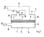
- the air filter housing 2 shown schematically in Fig. 1 consists of a Rohluftschale 4 and a clean air tray 6, both of which are tightly interconnected.
- an air filter 8 is arranged between these two shells 4 and 6, between these two shells 4 and 6, an air filter 8 is arranged.
- the feeder of unfiltered air LR in the housing 2 via a with the raw air space 4a in conjunction standing supply line 10 and then via the air filter 8 in the clean air space 6a and from there from the clean air LM via a supply line 12 to the intake of the Internal combustion engine supplied.
- an opening 13 is introduced into which a with a fabric structure provided insert member 14 is attached.
- the frame-like Insert 14 has a plurality of window-like openings 14a to 14e, of the technical tissue are covered.
- the technical fabric can be used on the Insert 14 sprayed on, welded, glued or clamped to the frame of Insert 14 to be attached.
- the insert 14 in turn can by means of a screw or Clip connection 16 to be attached to the clean air tray 4.
- the fabric ensures that by the swinging of the air column in the intake tract of the internal combustion engine On the other hand, it prevents sound components from being conducted to the outside Water, dirt or the like. From the outside via the opening 13 in the air filter housing. 2 can get.
- the tissue can optionally additionally be coated hydrophobic.
- the housing opening 13 through a thin-walled sound element is covered, the same or similar characteristics as having the tissue.
- the fabric or the sound element can oscillate in the process Insert 14 to be attached.
- a resonator 18 is integrated, the volume 20 via a pipe section 22 with the intake tract of the internal combustion engine leading supply line 12 is in communication.
- a Shut-off 24 arranged in the present embodiment as a flap formed and in its open position the resonator 20 with the Feed line 12 connects and in the closed state, the resonator 20 of the supply line 12 and thus separated from the intake of the engine.
- the flap member 24 via a linkage 26 with a Vacuum box 28 connected.
- the vacuum unit 28 is connected via a pressure line 30 with a vacuum accumulator, not shown, connected by a in the Pressure line 30 arranged switching valve 32, the connection between the pressure box 28th and vacuum reservoir is switched on or off.
- the resonator volume 20 is in the lower and middle speed range by closing the flap 24 separated from the intake of the engine to the excitation of the higher engine orders for sound transmission at a discrete frequency in the Interior to use.
- the flap 24 is opened and thus the resonator activates to the outgoing sound or sound level lower in this speed range due to resonance phenomena, stimulated by the dominant gas exchange regulations, especially in the intake system is highly trained.
Landscapes
- Engineering & Computer Science (AREA)
- Chemical & Material Sciences (AREA)
- Combustion & Propulsion (AREA)
- Mechanical Engineering (AREA)
- General Engineering & Computer Science (AREA)
- Analytical Chemistry (AREA)
- Manufacturing & Machinery (AREA)
- Filtering Of Dispersed Particles In Gases (AREA)
- Exhaust Silencers (AREA)
Abstract
Description
- Fig. 1
- eine schematische Darstellung eines Luftfiltergehäuses mit integriertem Resonator,
- Fig. 2
- eine Draufsicht auf das Luftfiltergehäuse,
- Fig. 3
- einen Schnitt entlang der Linie III - III in Fig. 2 und
- Fig. 4
- eine Innenansicht auf die Reinluftschale des Luftfiltergehäuses
Claims (6)
- Luftfilter für eine Brennkraftmaschine, mit einem Gehäuse, in dem ein Luftfilterelement angeordnet ist, welches zwischen einem Rohlufteinlass in einer Rohluftschale und einem Reinluftauslass in einer Reinluftschale angeordnet ist, sowie mit einer im Luftfiltergehäuse vorgesehenen Öffnung, die durch ein luftdurchlässiges und feinmaschiges Gewebe oder durch ein dünnwandiges Schallelement abgedeckt ist, dadurch gekennzeichnet, dass zur Optimierung der Schallabstrahlung auf der Reinluftseite ein Resonator (18) vorgesehen ist, der in Abhängigkeit vorgebbarer Motorparameter zu- bzw. abschaltbar ist.
- Luftfilter nach Anspruch 1, dadurch gekennzeichnet, dass das Resonatorvolumen (20) in der Reinluftschale (6) integriert und über einen Rohrleitungsabschnitt (22) mit einer zum Ansaugtrakt der Brennkraftmaschine führenden Rohrleitung (12) verbunden ist, wobei in dem Rohrleitungsabschnitt (22) ein Absperrelement (24) angeordnet ist.
- Luftfilter nach Anspruch 2, dadurch gekennzeichnet, dass das Absperrelement (24) als unterdruckgesteuertes Klappenelement ausgebildet ist.
- Luftfilter nach einem der vorhergehenden Ansprüche, dadurch gekennzeichnet, dass das die Öffnung (13) abdeckende Gewebe oder das Schallelement hydrophob beschichtet ist.
- Luftfilter nach einem der vorhergehenden Ansprüche, dadurch gekennzeichnet, dass das Gewebe oder das Schallelement von einem Rahmen umschlossen ist, der als Einsatzteil (14) in der Gehäuseöffnung (13) eingesetzt ist.
- Luftfilter nach Anspruch 1, dadurch gekennzeichnet, dass im unteren und mittleren Drehzahlbereich der Resonator (18) deaktiviert und im oberen Drehzahlbereich aktiviert ist.
Applications Claiming Priority (2)
| Application Number | Priority Date | Filing Date | Title |
|---|---|---|---|
| DE10356583 | 2003-12-04 | ||
| DE10356583A DE10356583A1 (de) | 2003-12-04 | 2003-12-04 | Luftfilter für eine Brennkraftmaschine |
Publications (3)
| Publication Number | Publication Date |
|---|---|
| EP1538329A2 true EP1538329A2 (de) | 2005-06-08 |
| EP1538329A3 EP1538329A3 (de) | 2010-12-01 |
| EP1538329B1 EP1538329B1 (de) | 2014-07-09 |
Family
ID=34442432
Family Applications (1)
| Application Number | Title | Priority Date | Filing Date |
|---|---|---|---|
| EP20040026359 Not-in-force EP1538329B1 (de) | 2003-12-04 | 2004-11-05 | Luftfilter für eine Brennkraftmaschine |
Country Status (2)
| Country | Link |
|---|---|
| EP (1) | EP1538329B1 (de) |
| DE (1) | DE10356583A1 (de) |
Cited By (1)
| Publication number | Priority date | Publication date | Assignee | Title |
|---|---|---|---|---|
| DE102017009492A1 (de) | 2017-10-12 | 2019-04-18 | Daimler Ag | Verfahren zur Einstellung einer Motorakustik einer Verbrennungskraftmaschine |
Families Citing this family (2)
| Publication number | Priority date | Publication date | Assignee | Title |
|---|---|---|---|---|
| DE102007026416B4 (de) | 2007-06-06 | 2014-09-04 | Audi Ag | Vorrichtung zur Beeinflussung des Ansauggeräusches einer Brennkraftmaschine |
| DE102019210078A1 (de) * | 2019-07-09 | 2021-01-14 | Mahle International Gmbh | Luftfiltermodul |
Citations (1)
| Publication number | Priority date | Publication date | Assignee | Title |
|---|---|---|---|---|
| EP1350945A2 (de) | 2002-03-27 | 2003-10-08 | Dr.Ing. h.c.F. Porsche Aktiengesellschaft | Luftfilter für eine Brennkraftmaschine |
Family Cites Families (4)
| Publication number | Priority date | Publication date | Assignee | Title |
|---|---|---|---|---|
| US4538556A (en) * | 1983-07-11 | 1985-09-03 | Toyota Jidosha Kabushiki Kaisha | Air intake device of an internal combustion engine |
| JPS6161910A (ja) * | 1984-08-31 | 1986-03-29 | Nippon Denso Co Ltd | 内燃機関用空気清浄器 |
| JP2564867B2 (ja) * | 1987-12-26 | 1996-12-18 | 日本電装株式会社 | 内燃機関の消音装置 |
| JP3846569B2 (ja) * | 2002-03-29 | 2006-11-15 | 株式会社デンソー | 吸気装置 |
-
2003
- 2003-12-04 DE DE10356583A patent/DE10356583A1/de not_active Withdrawn
-
2004
- 2004-11-05 EP EP20040026359 patent/EP1538329B1/de not_active Not-in-force
Patent Citations (1)
| Publication number | Priority date | Publication date | Assignee | Title |
|---|---|---|---|---|
| EP1350945A2 (de) | 2002-03-27 | 2003-10-08 | Dr.Ing. h.c.F. Porsche Aktiengesellschaft | Luftfilter für eine Brennkraftmaschine |
Cited By (1)
| Publication number | Priority date | Publication date | Assignee | Title |
|---|---|---|---|---|
| DE102017009492A1 (de) | 2017-10-12 | 2019-04-18 | Daimler Ag | Verfahren zur Einstellung einer Motorakustik einer Verbrennungskraftmaschine |
Also Published As
| Publication number | Publication date |
|---|---|
| DE10356583A1 (de) | 2005-07-07 |
| EP1538329B1 (de) | 2014-07-09 |
| EP1538329A3 (de) | 2010-12-01 |
Similar Documents
| Publication | Publication Date | Title |
|---|---|---|
| EP1350945B1 (de) | Luftfilter für eine Brennkraftmaschine | |
| DE102008005085B4 (de) | Verstellbare Helmholtz-Resonatoranordnung | |
| DE102011107677B4 (de) | Fahrzeugsitz | |
| DE4017074A1 (de) | Druckregelventil fuer die kurbelgehaeuseentlueftung an einer brennkraftmaschine | |
| WO2001081734A1 (de) | Schalldämpferanlage eines kraftfahrzeuges mit variabler dämpfungscharakteristik | |
| DE112015003965B4 (de) | Kraftstoffversorgungsvorrichtung | |
| WO2018077348A1 (de) | Vorrichtung zur verteilung von waschwasser mit multiventil | |
| DE102012000806A1 (de) | Resonatorsystem | |
| DE102008002314A1 (de) | Schallqualitätssteuerungsgerät für eine Brennkraftmaschine | |
| DE102005021797B4 (de) | Ansaugsystem eines Mehrzylindermotors | |
| DE102006058326B4 (de) | Variables Ansaugsystem eines Fahrzeuges | |
| EP1649918B1 (de) | Reinigungssystem für Entstaubungsfilter | |
| EP1538329B1 (de) | Luftfilter für eine Brennkraftmaschine | |
| DE102005052340B4 (de) | Kurbelgehäusedrucksteuerventil mit einem gebogenen Stutzen | |
| DE102007026416B4 (de) | Vorrichtung zur Beeinflussung des Ansauggeräusches einer Brennkraftmaschine | |
| EP0569714A1 (de) | Luftansaugvorrichtung für eine Brennkraftmaschine | |
| WO1995017593A1 (de) | Verfahren und anlage zur tankentlüftung | |
| DE69911922T2 (de) | Kraftstofffilter | |
| DE10304028A1 (de) | Luftfilter für eine Brennkraftmaschine | |
| DE19843772A1 (de) | Sauganlage für eine Brennkraftmaschine | |
| DE102005020442A1 (de) | Entlüftungseinrichtung für ein Kurbelgehäuse einer Brennkraftmaschine | |
| DE102012010690B4 (de) | Kraftfahrzeugsitz | |
| EP1172547B1 (de) | Ansaugsystem für ein Kraftfahrzeug | |
| EP1335124A1 (de) | Luftfilter für eine Brennkraftmaschine | |
| DE10062472C1 (de) | Abgas-System eines Kraftfahrzeuges |
Legal Events
| Date | Code | Title | Description |
|---|---|---|---|
| PUAI | Public reference made under article 153(3) epc to a published international application that has entered the european phase |
Free format text: ORIGINAL CODE: 0009012 |
|
| AK | Designated contracting states |
Kind code of ref document: A2 Designated state(s): AT BE BG CH CY CZ DE DK EE ES FI FR GB GR HU IE IS IT LI LU MC NL PL PT RO SE SI SK TR |
|
| AX | Request for extension of the european patent |
Extension state: AL HR LT LV MK YU |
|
| RAP1 | Party data changed (applicant data changed or rights of an application transferred) |
Owner name: DR. ING. H.C. F. PORSCHE AKTIENGESELLSCHAFT |
|
| RAP1 | Party data changed (applicant data changed or rights of an application transferred) |
Owner name: DR. ING. H.C. F. PORSCHE AKTIENGESELLSCHAFT |
|
| RAP1 | Party data changed (applicant data changed or rights of an application transferred) |
Owner name: DR. ING. H.C. F. PORSCHE AG |
|
| PUAL | Search report despatched |
Free format text: ORIGINAL CODE: 0009013 |
|
| AK | Designated contracting states |
Kind code of ref document: A3 Designated state(s): AT BE BG CH CY CZ DE DK EE ES FI FR GB GR HU IE IS IT LI LU MC NL PL PT RO SE SI SK TR |
|
| AX | Request for extension of the european patent |
Extension state: AL HR LT LV MK YU |
|
| RIC1 | Information provided on ipc code assigned before grant |
Ipc: F02B 27/02 20060101ALI20101025BHEP Ipc: F02M 35/14 20060101AFI20050413BHEP |
|
| 17P | Request for examination filed |
Effective date: 20110601 |
|
| AKX | Designation fees paid |
Designated state(s): DE FR GB IT |
|
| 17Q | First examination report despatched |
Effective date: 20111019 |
|
| GRAP | Despatch of communication of intention to grant a patent |
Free format text: ORIGINAL CODE: EPIDOSNIGR1 |
|
| INTG | Intention to grant announced |
Effective date: 20140128 |
|
| GRAS | Grant fee paid |
Free format text: ORIGINAL CODE: EPIDOSNIGR3 |
|
| GRAA | (expected) grant |
Free format text: ORIGINAL CODE: 0009210 |
|
| AK | Designated contracting states |
Kind code of ref document: B1 Designated state(s): DE FR GB IT |
|
| REG | Reference to a national code |
Ref country code: GB Ref legal event code: FG4D Free format text: NOT ENGLISH |
|
| REG | Reference to a national code |
Ref country code: DE Ref legal event code: R096 Ref document number: 502004014673 Country of ref document: DE Effective date: 20140814 |
|
| REG | Reference to a national code |
Ref country code: DE Ref legal event code: R097 Ref document number: 502004014673 Country of ref document: DE |
|
| PG25 | Lapsed in a contracting state [announced via postgrant information from national office to epo] |
Ref country code: IT Free format text: LAPSE BECAUSE OF FAILURE TO SUBMIT A TRANSLATION OF THE DESCRIPTION OR TO PAY THE FEE WITHIN THE PRESCRIBED TIME-LIMIT Effective date: 20140709 |
|
| PLBE | No opposition filed within time limit |
Free format text: ORIGINAL CODE: 0009261 |
|
| STAA | Information on the status of an ep patent application or granted ep patent |
Free format text: STATUS: NO OPPOSITION FILED WITHIN TIME LIMIT |
|
| 26N | No opposition filed |
Effective date: 20150410 |
|
| REG | Reference to a national code |
Ref country code: FR Ref legal event code: PLFP Year of fee payment: 12 |
|
| REG | Reference to a national code |
Ref country code: FR Ref legal event code: PLFP Year of fee payment: 13 |
|
| REG | Reference to a national code |
Ref country code: FR Ref legal event code: PLFP Year of fee payment: 14 |
|
| PGFP | Annual fee paid to national office [announced via postgrant information from national office to epo] |
Ref country code: FR Payment date: 20181123 Year of fee payment: 15 Ref country code: GB Payment date: 20181120 Year of fee payment: 15 |
|
| PGFP | Annual fee paid to national office [announced via postgrant information from national office to epo] |
Ref country code: DE Payment date: 20191024 Year of fee payment: 16 |
|
| GBPC | Gb: european patent ceased through non-payment of renewal fee |
Effective date: 20191105 |
|
| PG25 | Lapsed in a contracting state [announced via postgrant information from national office to epo] |
Ref country code: GB Free format text: LAPSE BECAUSE OF NON-PAYMENT OF DUE FEES Effective date: 20191105 Ref country code: FR Free format text: LAPSE BECAUSE OF NON-PAYMENT OF DUE FEES Effective date: 20191130 |
|
| REG | Reference to a national code |
Ref country code: DE Ref legal event code: R119 Ref document number: 502004014673 Country of ref document: DE |
|
| PG25 | Lapsed in a contracting state [announced via postgrant information from national office to epo] |
Ref country code: DE Free format text: LAPSE BECAUSE OF NON-PAYMENT OF DUE FEES Effective date: 20210601 |