EP1538128A2 - Abschlusskappe für eine Elektrolysezelle - Google Patents
Abschlusskappe für eine Elektrolysezelle Download PDFInfo
- Publication number
- EP1538128A2 EP1538128A2 EP04257495A EP04257495A EP1538128A2 EP 1538128 A2 EP1538128 A2 EP 1538128A2 EP 04257495 A EP04257495 A EP 04257495A EP 04257495 A EP04257495 A EP 04257495A EP 1538128 A2 EP1538128 A2 EP 1538128A2
- Authority
- EP
- European Patent Office
- Prior art keywords
- section
- end cap
- cell
- cylindrical
- membrane
- Prior art date
- Legal status (The legal status is an assumption and is not a legal conclusion. Google has not performed a legal analysis and makes no representation as to the accuracy of the status listed.)
- Granted
Links
Images


Classifications
-
- C—CHEMISTRY; METALLURGY
- C25—ELECTROLYTIC OR ELECTROPHORETIC PROCESSES; APPARATUS THEREFOR
- C25B—ELECTROLYTIC OR ELECTROPHORETIC PROCESSES FOR THE PRODUCTION OF COMPOUNDS OR NON-METALS; APPARATUS THEREFOR
- C25B9/00—Cells or assemblies of cells; Constructional parts of cells; Assemblies of constructional parts, e.g. electrode-diaphragm assemblies; Process-related cell features
-
- C—CHEMISTRY; METALLURGY
- C02—TREATMENT OF WATER, WASTE WATER, SEWAGE, OR SLUDGE
- C02F—TREATMENT OF WATER, WASTE WATER, SEWAGE, OR SLUDGE
- C02F1/00—Treatment of water, waste water, or sewage
- C02F1/46—Treatment of water, waste water, or sewage by electrochemical methods
- C02F1/461—Treatment of water, waste water, or sewage by electrochemical methods by electrolysis
- C02F1/46104—Devices therefor; Their operating or servicing
-
- C—CHEMISTRY; METALLURGY
- C25—ELECTROLYTIC OR ELECTROPHORETIC PROCESSES; APPARATUS THEREFOR
- C25B—ELECTROLYTIC OR ELECTROPHORETIC PROCESSES FOR THE PRODUCTION OF COMPOUNDS OR NON-METALS; APPARATUS THEREFOR
- C25B9/00—Cells or assemblies of cells; Constructional parts of cells; Assemblies of constructional parts, e.g. electrode-diaphragm assemblies; Process-related cell features
- C25B9/17—Cells comprising dimensionally-stable non-movable electrodes; Assemblies of constructional parts thereof
- C25B9/19—Cells comprising dimensionally-stable non-movable electrodes; Assemblies of constructional parts thereof with diaphragms
-
- C—CHEMISTRY; METALLURGY
- C25—ELECTROLYTIC OR ELECTROPHORETIC PROCESSES; APPARATUS THEREFOR
- C25B—ELECTROLYTIC OR ELECTROPHORETIC PROCESSES FOR THE PRODUCTION OF COMPOUNDS OR NON-METALS; APPARATUS THEREFOR
- C25B9/00—Cells or assemblies of cells; Constructional parts of cells; Assemblies of constructional parts, e.g. electrode-diaphragm assemblies; Process-related cell features
- C25B9/60—Constructional parts of cells
- C25B9/63—Holders for electrodes; Positioning of the electrodes
-
- C—CHEMISTRY; METALLURGY
- C02—TREATMENT OF WATER, WASTE WATER, SEWAGE, OR SLUDGE
- C02F—TREATMENT OF WATER, WASTE WATER, SEWAGE, OR SLUDGE
- C02F1/00—Treatment of water, waste water, or sewage
- C02F1/28—Treatment of water, waste water, or sewage by sorption
- C02F1/283—Treatment of water, waste water, or sewage by sorption using coal, charred products, or inorganic mixtures containing them
-
- C—CHEMISTRY; METALLURGY
- C02—TREATMENT OF WATER, WASTE WATER, SEWAGE, OR SLUDGE
- C02F—TREATMENT OF WATER, WASTE WATER, SEWAGE, OR SLUDGE
- C02F1/00—Treatment of water, waste water, or sewage
- C02F1/46—Treatment of water, waste water, or sewage by electrochemical methods
- C02F1/461—Treatment of water, waste water, or sewage by electrochemical methods by electrolysis
- C02F1/46104—Devices therefor; Their operating or servicing
- C02F1/46109—Electrodes
-
- C—CHEMISTRY; METALLURGY
- C02—TREATMENT OF WATER, WASTE WATER, SEWAGE, OR SLUDGE
- C02F—TREATMENT OF WATER, WASTE WATER, SEWAGE, OR SLUDGE
- C02F1/00—Treatment of water, waste water, or sewage
- C02F1/46—Treatment of water, waste water, or sewage by electrochemical methods
- C02F1/461—Treatment of water, waste water, or sewage by electrochemical methods by electrolysis
- C02F1/467—Treatment of water, waste water, or sewage by electrochemical methods by electrolysis by electrochemical disinfection; by electrooxydation or by electroreduction
- C02F1/4672—Treatment of water, waste water, or sewage by electrochemical methods by electrolysis by electrochemical disinfection; by electrooxydation or by electroreduction by electrooxydation
- C02F1/4674—Treatment of water, waste water, or sewage by electrochemical methods by electrolysis by electrochemical disinfection; by electrooxydation or by electroreduction by electrooxydation with halogen or compound of halogens, e.g. chlorine, bromine
-
- C—CHEMISTRY; METALLURGY
- C02—TREATMENT OF WATER, WASTE WATER, SEWAGE, OR SLUDGE
- C02F—TREATMENT OF WATER, WASTE WATER, SEWAGE, OR SLUDGE
- C02F1/00—Treatment of water, waste water, or sewage
- C02F1/48—Treatment of water, waste water, or sewage with magnetic or electric fields
-
- C—CHEMISTRY; METALLURGY
- C02—TREATMENT OF WATER, WASTE WATER, SEWAGE, OR SLUDGE
- C02F—TREATMENT OF WATER, WASTE WATER, SEWAGE, OR SLUDGE
- C02F1/00—Treatment of water, waste water, or sewage
- C02F1/46—Treatment of water, waste water, or sewage by electrochemical methods
- C02F1/461—Treatment of water, waste water, or sewage by electrochemical methods by electrolysis
- C02F1/46104—Devices therefor; Their operating or servicing
- C02F1/46109—Electrodes
- C02F2001/46133—Electrodes characterised by the material
- C02F2001/46138—Electrodes comprising a substrate and a coating
-
- C—CHEMISTRY; METALLURGY
- C02—TREATMENT OF WATER, WASTE WATER, SEWAGE, OR SLUDGE
- C02F—TREATMENT OF WATER, WASTE WATER, SEWAGE, OR SLUDGE
- C02F2201/00—Apparatus for treatment of water, waste water or sewage
- C02F2201/002—Construction details of the apparatus
- C02F2201/003—Coaxial constructions, e.g. a cartridge located coaxially within another
-
- C—CHEMISTRY; METALLURGY
- C02—TREATMENT OF WATER, WASTE WATER, SEWAGE, OR SLUDGE
- C02F—TREATMENT OF WATER, WASTE WATER, SEWAGE, OR SLUDGE
- C02F2201/00—Apparatus for treatment of water, waste water or sewage
- C02F2201/46—Apparatus for electrochemical processes
- C02F2201/461—Electrolysis apparatus
- C02F2201/46105—Details relating to the electrolytic devices
- C02F2201/46115—Electrolytic cell with membranes or diaphragms
-
- C—CHEMISTRY; METALLURGY
- C02—TREATMENT OF WATER, WASTE WATER, SEWAGE, OR SLUDGE
- C02F—TREATMENT OF WATER, WASTE WATER, SEWAGE, OR SLUDGE
- C02F2201/00—Apparatus for treatment of water, waste water or sewage
- C02F2201/46—Apparatus for electrochemical processes
- C02F2201/461—Electrolysis apparatus
- C02F2201/46105—Details relating to the electrolytic devices
- C02F2201/4612—Controlling or monitoring
- C02F2201/46145—Fluid flow
-
- C—CHEMISTRY; METALLURGY
- C02—TREATMENT OF WATER, WASTE WATER, SEWAGE, OR SLUDGE
- C02F—TREATMENT OF WATER, WASTE WATER, SEWAGE, OR SLUDGE
- C02F2209/00—Controlling or monitoring parameters in water treatment
- C02F2209/04—Oxidation reduction potential [ORP]
-
- C—CHEMISTRY; METALLURGY
- C02—TREATMENT OF WATER, WASTE WATER, SEWAGE, OR SLUDGE
- C02F—TREATMENT OF WATER, WASTE WATER, SEWAGE, OR SLUDGE
- C02F2209/00—Controlling or monitoring parameters in water treatment
- C02F2209/06—Controlling or monitoring parameters in water treatment pH
Definitions
- This invention relates to an insulating end cap construction for a cylindrical electrolysis cell of the type comprising at least two tubular electrodes arranged coaxially, one within the other, with a cylindrical membrane arranged coaxially between them.
- Cells of the type to which the invention relates can be used for example for sanitising water through electrolysis for drinking purposes, or electrolysing brine solutions to make a powerful biocide.
- Many types of electrochemical activation and electrolysis cells exist for this purpose, and generally comprise two concentric cylindrical electrodes, one of which acts as a cathode and the other as an anode, an ion-permeable membrane being located coaxially between them to separate the space between the electrodes into anode and cathode compartments.
- An electrolyte such as brine is passed through the anode and cathode compartments, separately or successively.
- EP-A-922788 discloses an electrolytic cell in which the two concentric electrodes and the membrane are received in unitary end bushes, each having a central aperture for passage of the inner electrode with surrounding concentric seatings for the membrane and the outer electrode.
- Cells of this type function quite well, but a problem arises in their construction. A high degree of craft skill is required to assemble them, and in particular to assemble the cell components in the end bushes, and there is a high breakage rate. With brittle ceramic cylindrical membranes, damage rates can be as high as 1 in 5.
- Another problem to which the present invention is addressed is that of making the cylindrical cell leak-free and pressure-resistant.
- Many existing cells start leaking over a period of time as component parts are mechanically sealed with gaskets. During the lifetime of a cell, component parts become brittle, shrink or expand, causing leakages.
- the present invention provides an insulating end cap for a cylindrical electrolysis cell of the type comprising at least two tubular electrodes arranged coaxially one within the other with a cylindrical membrane arranged coaxially between them, said end cap comprising:
- the assembly of the cell can be greatly simplified, avoiding damage to components and allowing easier visual inspection at all stages of construction. Craft skills are not necessary, and sealants can more easily be used, avoiding the need for mechanical gasket or O-ring seals. The use of such non-toxic sealants helps to avoid leakages and imparts increased pressure resistance.
- the sealants and the end caps can be made of a plastics material that is approved for medical purposes, and can be in contact with drinking water.
- the preferred sealants are two-part epoxy sealants which possess a high chemical resistance as well as a high degree of flexibility, so that seals are maintained even when components shrink or expand during the electrolysis process.
- the second annular section is preferably secured to the first by means of a screw thread. This means that the end cap can be assembled and secured to the cylindrical cell components without the need to apply force to overcome friction.
- a third annular section is secured to the second section, this third section having a central circular aperture of similar diameter to that of the aperture in the second section and serving to enhance a sealing engagement between the end cap and an inner cylindrical electrode passing through said apertures of the second and third sections.
- This third section is preferably secured to the second section by means of a screw thread, for the same reasons as discussed above in connection with the first and second sections.
- first and second sections of the end cap may be provided with lateral inlets through their outer walls, for the passage of electrolyte into or out of the cell compartments defined between the electrodes and the membrane.
- the inlets can be provided axially between the seating for the first electrode and the circular aperture through which the membrane passes.
- the inlet can be provided axially between the first and second ends.
- the lateral inlets are preferably arranged for tangential feed into the cell compartments so that a spiral flow pattern of the electrolyte through the anode or cathode chamber is achieved.
- the electrolyte inlets are preferably equipped with John Guest fittings for sealing connections to electrolyte inlet or outlet pipes.
- a cylindrical electrolysis cell comprising at least two tubular electrodes arranged coaxially, one within the other, with a cylindrical ion-permeable membrane arranged coaxially between them, wherein there is provided at at least one end of the cell an insulating end cap as defined above, one end of a radially outer electrode of the cell being located in the circular seating at the first end of the first annular section, one end of the cylindrical membrane being located in the circular aperture at the second end of the first section and one end of an inner tubular electrode being located in the central aperture of the second section.
- This arrangement is preferably provided at both ends of the cell.
- the cell membrane is preferably a ceramic ion-permeable membrane, more preferably comprising alumina and/or zirconia.
- One preferred type of membrane comprises Al 2 O 3 particles with a mean particle size of 3 to 5 ⁇ m and ZrO 2 particles with a mean particle size of 0.3 to 0.8 ⁇ m.
- the end cap construction of the present invention means that relatively fragile membranes can be used.
- the membrane preferably has a thickness of 1-2 mm.
- the membrane can be made as a slip and fixed in cylindrical form.
- both the anode and the cathode can be made from titanium, and at least the anode is preferably coated with a mixed oxide for enhanced performance.
- both the anode and the cathode are made from titanium and coated with a mixed oxide.
- the preferred coating structures are made from platinum or platinum metal oxides, which may be mixed with other transition metal oxides. Preferred coatings will be discussed in more detail below.
- biocidal liquids can be produced in the electrolysis cells of the present invention, depending on the pipework configuration (flow pattern through the cell).
- the electrolyte can be fed to the anode and cathode compartments and the electrolysed liquid can then be collected from each of these compartments separately.
- the electrolyte can be fed through both electrode chambers successively.
- Other factors which can be used to vary the biocidal liquid include the voltage applied to the electrodes, the electrical power absorbed, the electrode coating and physical size of the electrode, the shape of the electrodes and distances between them and the spacing and material of the membrane.
- the membrane material is also an important feature since it affects the mobility of ions passing between the electrodes.
- the preferred mixed oxide coated electrodes comprise a titanium base activated with a coating structure which may comprise platinum, preferably in finely divided form such as platinum black, or platinum metal oxide mixed with oxides of one or more other transition metal oxides such as those of titanium, tantalum, niobilum, iridium, ruthenium, rhodium or palladium oxides, or mixtures thereof.
- a coating structure which may comprise platinum, preferably in finely divided form such as platinum black, or platinum metal oxide mixed with oxides of one or more other transition metal oxides such as those of titanium, tantalum, niobilum, iridium, ruthenium, rhodium or palladium oxides, or mixtures thereof.
- the particular coating selected will depend on the application. By depositing a number of layers, one upon the other, a noble metal mixed oxide coating can be obtained on the titanium substrate. Each layer may be less than 1 ⁇ m thick.
- the metal compounds are dissolved in organic solvents, applied to the surface and decomposed after
- the preferred coating is a ruthenium mixed metal oxide or a platinum-iridium oxide coating on the titanium anode, depending on for example the temperature of the sea water and its salinity.
- the electrolyte feed liquid comprises a brine feed of mains water mixed with sodium chloride for the production of biocidal liquids
- a ruthenium mixed metal oxide coating is preferably applied to the titanium electrode. This is to ensure an optimal conversion of electrolyte into biocidal liquid. Deposits of electrolyte or brine in the biocidal liquid are minimised, and the content of active chlorine is maximised.
- the preferred electrodes are coated with a platinum-iridium oxide coating or a ruthenium mixed metal oxide coating. This is to ensure the maximum production of oxygen within the electrolytic cell.
- the biocidal liquids produced in the electrolytic cell can have a pH varying from 2 to 8.5 and an essentially positive redox potential, typically in the range from +600 to +1200 mV.
- a wetting alkaline liquid can be produced with a strongly negative redox potential, typically in the range from -800 mV to -1100 mV, depending on the conditions applied to the cell.
- the negatively charged alkaline liquids are not stable and last only for about 48 hours before losing their charge. They have been used as a powerful anti-oxidant within the bodies of fish and mammals to boost the immune system. They have many other uses.
- the positively charged biocidal liquids can be sustained in what are stable solutions for up to two years given certain production conditions within the electrolytic cell. Although many large users of biocides may find it advantageous to manufacture fresh biocidal liquids, it can be shown that a sporicidal effect can be achieved with biocidal liquid blends for up to five months.
- This invention sets out to produce an electrolytic cell with some unique features that address the problems of robustness, general reliability, cost, performance, ease of manufacture and quality control (traceability and usage of approved materials).
- a method of electrolysing water or brine in an electrolysis cell comprising anode and cathode compartments separated by an ion-permeable membrane, wherein the cell has an anode and a cathode made of titanium having thereon a coating structure made from platinum mixed with at least one oxide of another transition metal.
- the system used allows for two things to happen:
- Sanitising water for drinking purposes is achieved using a diaphramatic electrolyses cell and an active-coal filter, in which water is purified in several stages:
- First stage is the oxidation of water and its substances. Bacteria, viruses and organic substances are destroyed (oxidised).
- the water is saturated with short-lived oxidants, such as HClO, ClO 2 , O 3 , O 2 , H 2 O 2 , OH.
- the second stage takes place in a reaction chamber, where oxidation processes continue.
- the third stage consists of catalytic destruction of active chlorine compounds; removal of organic substances, taste and taint using activated coal as a sorbent.
- the final stage consists of reduction of tap water and its substances. Toxic heavy metal ions and hazardous organic substances such as herbicides, pesticides, phenols and dioxins are transformed into non-toxic hydroxyls.
- the water is saturated with anti-oxidants: OH - , HO 2 - and O 2 .
- Electrolysis of water take place at the surface of mixed-oxide noble metal coated electrodes within the electrolytic cell. Free radicals are released during electrolysis like hydroxyls, oxidants, such as oxygen and ozone to sanitize the water passing through the anode and cathode chamber of an electrolytic cell. In order to "plate” out metals and break down organic molecules into harmless components an anthracite and activated carbon chamber are fitted next to the electrolytic cell. Part of this sanitizing process puts a predominantly negative charge on the water. This property makes the water an anti-oxidant. Anti-oxidants have many uses.
- This invention seeks to use a standard cylindrical electrolysis cell which has been developed for water or brine electrolysis. Take advantage of the modular nature of the electrolytic cell and try to create an electrochemical activation process which can be tailored to address the many diverse applications.
- This electrochemical activation of a brine solution is achieved using a cylindrical diaphragm electrolysis cell (an electrolytic cell).
- the electrolytic cell can produce various biocidal liquids, depending on the electrical power supply, the current drawn, brine feed and flow pattern convention.
- Electrochemically received anolyte and catholyte leave the electrolysis cell by separate channels in the upper part of the electrolysis cell.
- the disadvantage of these electrolysis cells is the possibility of gas-filled zones forming in the upper part of electrode chambers, so that considerable losses of electricity occur which are due to counter-flow of electrochemically obtained gases and electrolytes.
- water to be electrolysed is preferably supplied to both chambers in the lower part of an electrolytic cell, and the anolyte and catholyte received are removed separately from the upper parts of the separated chambers.
- a spiral feed of electrolyte into the anode and cathode chambers leads to turbulization of the electrolytes in the chambers of the electrical cell, prolongs influence of electrolysis over elementary amounts of the processed water solutions, simplifies removal of gaseous and liquid products of electrolysis and reduces possible formation of gas-filled zones in the upper points of electrode chambers.
- outer cylindrical electrode and membrane, and between membrane and inner cylindrical electrode form separated electrode chambers whose geometric dimensions preferably satisfy the following:
- the relation between the anode and the cathode should preferably be roughly 1:1.40 - 1:1.50 respectively with a spacing between the electrodes (separated from the membrane) of 9mm to 21mm depending on the capacity of the electrolytic cell and the product requirements.
- the length of the ion exchange area can be varied depending on the volume required.
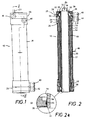
- a cylindrical electrolysis cell generally indicated by 10 comprises an outer cylindrical anode 12 enclosed on its outer surface by a cylindrical protective and insulating sleeve 14.
- This electrode is preferably made of titanium, coated on its inner surface with a transition metal oxide coating as described above.
- An inner cylindrical cathode 16 also preferably made of titanium and with a transition metal oxide coating on its outer surface, is arranged co-axially within the cylindrical anode, and a cylindrical ion-permeable membrane 18 is arranged co-axially between the electrodes in such a way as to define a space 20 between the anode and the membrane, which in use acts as an anolyte compartment, and a space 22 between the membrane and the cathode, which in use becomes the catholyte compartment.
- the ion-permeable membrane 18 is preferably a ceramic membrane, and is suitably made from allumina.
- An insulating end cap 23 is provided at each end of the cell, the end caps each comprising three annular sections which are co-axial with one another and secured together by means of screw threads.
- the three sections 24, 32 and 36 can best be seen in Figure 2.
- the first annular section 24 has three circular apertures 26, 28 and 30.
- the aperture 26 is surrounded by an annular end face 27, against which bears one end of the insulating sleeve 14.
- the aperture 26 has an inner diameter which matches the outer diameter of the cylindrical anode 12, and is separated from the aperture 28 by an annular shoulder 27, lying in a plane perpendicular to the longitudinal axis of the cell, and which acts as a seating for one end of the cylindrical anode 12.
- the innermost circular aperture 30 of the first annular section has an inner diameter such as to match the outer diameter of the membrane 18, such that the membrane can be slid into this section without the need to overcome substantial friction but without significant play when it is in position.
- a second annular section 32 of insulating material is detachably secured by a screw thread 33 to an end of the first section 24 which is remote from the seating 27 for the anode.
- This annular section has a circular recess within it, which is of larger diameter than the membrane 18, so that the second section can be screwed onto the first without touching the membrane, which may be projecting axially beyond the first section.
- the second section of the end cap has a circular aperture 34 which accommodates one axial end of the cylindrical cathode 16.
- the third annular section 36 is detachably secured to the second annular section 32 by means of a screw thread 39, and has a central circular aperture 38 of similar diameter to that of the second section.
- the third annular section serves to enhance a ceiling engagement between the end cap 23 and the cathode 16.
- the central circular aperture 34 of the second annular section 32 has a circumferential channel 41 accommodating a ceiling ring 43 to enhance the seal between the second section and the cathode 16.
- a radially projecting terminal 48 is provided for the anode 12, about half way along its axial length, and a similarly shaped terminal 50 is provided at one axial end of the cathode 16.
- the two end cap assemblies at opposite ends of the cell are essentially the same, and each has a pair of John Guest fitting for ceiling connections of inlet and outlet pipes for electrolytes. Each of these fittings connects to a lateral inlet through one of the annular sections of the end caps, transverse to the longitudinal direction of the cell and offset from the central axis of the cell.
- an inlet fitting 40 passes through the first annular section of the end cap to the space 20 which forms the anode chamber.
- a corresponding fitting 44 is provided as an outlet connection from the anode chamber.
- a John Guest fitting 42 at the lower end of the cell provides an inlet connection through the second end cap section 32 to the anode chamber, and at the upper end of the cell a corresponding fitting 46 provides an outlet connection from the anode chamber.
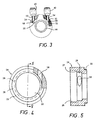
- FIG. 3 The bottom plan view of Figure 3 shows the electrolyte inlets in more detail.
- the John Guest fitting 40 connects to an inlet tube 52 which passes tangentially through the first section 24 of the lower end cap to communicate with the anode chamber 20 through an aperture 56.
- John Guest fitting 42 connects to an inlet pipe 54 through an aperture 58 in the second section 32 of the end cap, to feed electrolyte into the cathode chamber 22.
- a similar arrangement at the upper end of the cathode chamber 22 provides an outlet from the chamber through a John Guest fitting 46.
- the inlet tubes 52 and 54 enter the respective anode and cathode chambers tangentially to impart a spiral motion to the electrolyte passing through each of the chambers. This enhances mixing of the electrolyte, with consequent benefit to the electrolysis process.
- first section 24 of the end cap is shown in more detail in Figures 4 and 5, which show the screw thread 33 at the second end of the section, the three co-axial apertures 26, 28 and 30 and the shape of the tangential inlet ball 56 where it enters the aperture 28. Also illustrated is the shoulder 27 which acts as a seating for the axial end of the anode.
- Figures 6 and 7 show a plan view of the second end cap section 32, from the side which connects to the first section. This shows the inside of the screw thread 33 and the inner aperture 34, as well as the tangential inlet 58 for the electrolyte.
- the cross-sectional view 7 also shows the screw thread 39 to which the third end cap section is attached.
- a two pack epoxy sealant is used to seal around the axial ends of the anode 12 where it seats in the end cap first section 24, around the outside of the axial ends of the membrane where they are received in the aperture 30 of the end cap first sections and around the axial ends of the cathode 16 where they are received in the apertures 34 of the second end cap sections.
- the ceramic ion permeable membrane should preferably have a low hydraulic resistance and a high mechanical strength.
- the porosity and the pore size of the ceramic are important for electrolysis and depend on the nature of the particles in the slurry.
- ceramic ion permeable membranes can be manufactured by cast forming a slurry of a mixture of non-metallic and/or metallic particles in a porous mould.
- a slurry contains fine particles, but the majority are coarse particles. Most commonly used materials for the particles are alumina, mullite and zirconium-dioxide, but other materials can be used to give the membrane specific characteristics.
- the slurry is applied to a porous mould, the slurry is fired at a temperature between 1100-1300 °C. Firing is executed in a controlled environment in order to sinter the membrane without formation of cracks due to shrinkage and differences in the thermal expansion coefficient of the particles.
- FIG 8 shows an example of an electrolyser system and a typical flow through such a system.
- the process of the present invention may be operated as illustrated by and with reference to Figure 8 as follows:
- a water supply 70 such as towns water, is fed via an optional pre-heater 72 which is typically controlled at from 30 to 40 °C through feed lines around which are wound aerials of a low band frequency radio wave transmitter 74.
- the water is optionally passed through a hard salt deioniser 76.
- the towns water supply feeds both the mixer column 78, and the brine tank 80.
- the towns water supply to the mixer column 78 is used to dilute the brine solution feed.
- the towns water supply to the brine tank is used to prepare the brine solution, typically from sodium chloride and towns water.
- the towns water feed line has a T-connector 75 to direct the towns water feed to the mixer column and to the brine tank.
- a first valve 77 in a first feed line after the T-connector in the towns water feed line controls the flow of towns water to the mixer column 78;
- a second valve 79 in a second feed line after the T-connector 75, in the towns water feed line controls the flow of towns water to the brine tank. Regulation of these valves controls the flow of towns water to the mixer column and to the brine tank.
- a second T-connector 81 is situated downstream of the valve 77 between the towns water supply and the mixer column.
- Regulation of the first and third valves allows the concentration of brine fed to and exiting from the mixer column to be controlled. It will be appreciated that closing the third valve 82 will isolate the brine feed to the mixer column and result in only towns water being fed into the mixer column.
- the first, second and third valves may be automated and controlled in response to a suitable signal from the electrolyser system.
- the second valve 79 may be controlled by a level detector 83 in the brine tank, the valve closing when a particular pre-set level is reached.
- the first and third valves 79, 82 may be controlled by a suitable means such as a conductivity detector 84 situated before or after the mixer column which adjusts the relative flows of towns water to obtain a pre-set range of conductivity. Further the first and third valves may be controlled by a redox meter or pH meter measuring the redox or pH value of the liquid medium exiting the electrolyser(s) (E). In this example the feed liquid exiting the mixer column 78 is caused to flow into the anode chamber 85 of the first electrolyser 90 and from the anode chamber to the cathode chamber 88 of the first electrolyser.
- the liquid exiting the cathode chamber 88 of the first electrolyser is caused to flow into the anode chamber 92 of a second electrolyser 91 and from the anode chamber to the cathode chamber 94 of the second electrolyser.
- the feed liquid On its way from the mixer column to the first electrolyser the feed liquid is subjected to further radio waves from a generator 86.
- the liquid medium exiting the electrolyser, or if more than one electrolyser the last electrolyser 91, is caused to flow into a gas entrainment column 95 where gases such as hydrogen, oxygen, ozone and chlorine which are produced in the process are disengaged.
- the gas entrainment column is typically made of glass or plastics material which is packed with an inert support, such as plastics rings.
- a non-foaming non-ionic surfactant held in a surfactant tank 100 may be fed into the liquid medium exiting the electrolyser 90 either before or after the gas entrainment column 95 (shown as before in Figure 8).
- the surfactant may be fed into the liquid medium via a T-connector 102 and using a suitable pump, such as a peristaltic pump, to transfer the surfactant.
- the liquid medium exiting the gas entrainment column is ready for use as a broad spectrum biocide in sterilization, disinfection, and bio-film removal applications and the like.
- a central power supply and control unit 150 controls the power supply to the electrolysers 90, 92 via transformers 152, 154, and also controls the operation of the valves and radio wave generators. It will be appreciated that any number of electrolysers may be operated in series or in parallel as part of the electrolyser system. It will be further appreciated that the pipework connecting the electrolysers may be arranged in different ways to provide liquid media with different characteristics.
- the liquid medium exiting the anode chamber is collected via an outlet from the anode chamber (not shown in Figure 8).
- part of the liquid medium exiting the anode chamber is collected and part is fed into the cathode chamber via a T-connector and outlet (not shown in Figure 8).
- the feed liquid exiting the mixer column 78 is fed via a manifold device into electrolysers connected in parallel.
- the resulting solution is known as "hanolyte neutral catholyte (ANK) solution".
- ANK n-butane neutral catholyte
- This typically has a pH between 7 and 8.9, preferably 7.7 +/- 0.5.
- ANK n-butane neutral catholyte
- ANK n-butane neutral catholyte
- ANK n-butane neutral catholyte
- ANK a rectified square wave direct current is applied across the electrodes.
- the electrical system applies a steady current based on the saline content of the brine flowing through the cell. This is set to certain working perimeters.
- the current is preferably at least 20 amps, depending on the volume and length of the cell, to ensure a good sporicidal liquid flow.
- Minimum brine concentrations ensure that the residues in the product are at a minimum.
- the running temperature that is generated should be below 55°C.
- the electrical system is self monitoring in terms of working perimeters and also has a reverse polarity feature. This enables any surface contamination to be removed, and can be activated as desired, especially when running in a neutral product mode.
- a mineralised water feed with a TDS of about 300 microsiemens (0.3 g/l) is enough to draw sufficient current (at least 2.5 amps) to ensure that the product is germ free and negatively charged to -100 milli-volts on the redox metre.
- the voltage applied can be varied according to the mineralisation of the water, which should not be less than 250 microsiemens (0.25 g/l).
Landscapes
- Chemical & Material Sciences (AREA)
- Organic Chemistry (AREA)
- Chemical Kinetics & Catalysis (AREA)
- Electrochemistry (AREA)
- Engineering & Computer Science (AREA)
- Materials Engineering (AREA)
- Metallurgy (AREA)
- Life Sciences & Earth Sciences (AREA)
- General Chemical & Material Sciences (AREA)
- Hydrology & Water Resources (AREA)
- Environmental & Geological Engineering (AREA)
- Water Supply & Treatment (AREA)
- Electrolytic Production Of Non-Metals, Compounds, Apparatuses Therefor (AREA)
- Water Treatment By Electricity Or Magnetism (AREA)
- Electrodes For Compound Or Non-Metal Manufacture (AREA)
Applications Claiming Priority (2)
| Application Number | Priority Date | Filing Date | Title |
|---|---|---|---|
| GB0328124 | 2003-12-04 | ||
| GBGB0328124.3A GB0328124D0 (en) | 2003-12-04 | 2003-12-04 | Membrane electrolyser with a two part end design |
Publications (3)
| Publication Number | Publication Date |
|---|---|
| EP1538128A2 true EP1538128A2 (de) | 2005-06-08 |
| EP1538128A3 EP1538128A3 (de) | 2005-11-09 |
| EP1538128B1 EP1538128B1 (de) | 2017-07-26 |
Family
ID=29764573
Family Applications (1)
| Application Number | Title | Priority Date | Filing Date |
|---|---|---|---|
| EP04257495.4A Expired - Lifetime EP1538128B1 (de) | 2003-12-04 | 2004-12-02 | Abschlusskappe für eine Elektrolysezelle |
Country Status (3)
| Country | Link |
|---|---|
| US (2) | US7691249B2 (de) |
| EP (1) | EP1538128B1 (de) |
| GB (2) | GB0328124D0 (de) |
Cited By (10)
| Publication number | Priority date | Publication date | Assignee | Title |
|---|---|---|---|---|
| EP1860209A2 (de) | 2006-05-25 | 2007-11-28 | Aquastel International B.V. | Elektrolysezellenanordnung |
| WO2007115179A3 (en) * | 2006-03-31 | 2008-05-22 | Potable Water Systems Ltd | Process and apparatus for sewage water purification |
| WO2011073714A1 (en) * | 2009-12-16 | 2011-06-23 | Cm Ventures Ltd. | Multi-chamber electrolytic cell and methods of use |
| WO2011082784A1 (de) * | 2009-12-15 | 2011-07-14 | Finatep Ag | Flüssigkeitsaufbereitungsgerät zur elektrochemischen behandlung von flüssigkeiten und verfahren hierzu |
| GB2483555A (en) * | 2010-09-09 | 2012-03-14 | Valeri Iltshenko | Diaphragm Electrolyser for Disinfectant Production |
| US8152990B2 (en) | 2006-03-31 | 2012-04-10 | Potable Water Systems Ltd. | Water purification using conveyor sweep |
| EP2631334A1 (de) * | 2012-02-24 | 2013-08-28 | Caliopa AG | Elektrolysezelle, insbesondere zur Verwendung in einer Anlage zur Erzeugung einer elektrochemisch aktivierten Kochsalzlösung, sowie Anlage mit einer Anzahl derartiger Elektrolysezellen |
| WO2013090560A3 (en) * | 2011-12-13 | 2013-12-19 | Aquaox Inc. | Dual diaphragm electrolysis cell assembly and method for generating a cleaning solution without any salt residues and simultaneously generating a sanitizing solution having a predetermined level of available free chlorine and ph |
| WO2014113178A1 (en) * | 2012-12-18 | 2014-07-24 | Aquaox, Inc. | Apparatus and method for generating a stabilized sanitizing solution |
| US9139459B2 (en) | 2013-05-27 | 2015-09-22 | LUSIA KLING MILLER, Trustee of the Miller Family Trust and Luisa Kling Miller Survivor's Trust | Process and system for removal of naphthenic acid from an aqueous solution |
Families Citing this family (50)
| Publication number | Priority date | Publication date | Assignee | Title |
|---|---|---|---|---|
| JP5140218B2 (ja) | 2001-09-14 | 2013-02-06 | 有限会社コヒーレントテクノロジー | 表面洗浄・表面処理に適した帯電アノード水の製造用電解槽及びその製造法、並びに使用方法 |
| CA2468856C (en) | 2001-12-05 | 2011-07-26 | Osao Sumita | Method and apparatus for producing negative and positive oxidative reductive potential (orp) water |
| US9168318B2 (en) | 2003-12-30 | 2015-10-27 | Oculus Innovative Sciences, Inc. | Oxidative reductive potential water solution and methods of using the same |
| BRPI0609429B8 (pt) | 2005-03-23 | 2021-07-20 | Invekra S A P I De C V | uso de uma solução aquosa com potencial de oxirredução (orp) |
| CN101189017B (zh) | 2005-05-02 | 2013-04-03 | 奥古露丝创新科学公司 | 在牙科应用中使用氧化还原电位水溶液的方法 |
| EP1993571B1 (de) | 2006-01-20 | 2018-07-25 | Sonoma Pharmaceuticals, Inc. | Verfahren zur behandlung oder prävention von entzündungen und allergien mit einer wasserlösung mit redoxpotenzial |
| US20080116144A1 (en) | 2006-10-10 | 2008-05-22 | Spicer Randolph, Llc | Methods and compositions for reducing chlorine demand, decreasing disinfection by-products and controlling deposits in drinking water distribution systems |
| EE05447B1 (et) * | 2007-04-30 | 2011-08-15 | Ilt�enko Valeri | Kahekambrilise koaksiaalse elektrolseri protsessiseadis |
| US9486481B2 (en) | 2007-10-30 | 2016-11-08 | Reoxcyn Discoveries Group, Inc. | Method of modulating fatty acid mobilization and oxidation |
| EE05494B1 (et) * | 2008-04-23 | 2011-12-15 | Valeri Iltshenko | Silindriline diafragma-elektrolser koostatava anoodi ja diafragmaga |
| WO2010011927A1 (en) | 2008-07-25 | 2010-01-28 | Noventis, Inc. | Compositions and methods for the prevention and treatment of cardiovascular diseases |
| US9315907B2 (en) * | 2008-11-14 | 2016-04-19 | Mohammed Khodabakhsh | Gas collection device and method for use thereof |
| CA2703316A1 (en) * | 2009-05-06 | 2010-11-06 | Stuart A. Emmons | Electrolytic cell diaphragm/membrane |
| US10342825B2 (en) | 2009-06-15 | 2019-07-09 | Sonoma Pharmaceuticals, Inc. | Solution containing hypochlorous acid and methods of using same |
| US9777383B2 (en) * | 2010-01-08 | 2017-10-03 | Clarentis Holding, Inc. | Cell and system for preparation of antimicrobial solutions |
| EP2521455A4 (de) * | 2010-01-08 | 2014-10-01 | Clenox Man Llc | System und verfahren zur herstellung antimikrobieller lösungen |
| JP2013532661A (ja) | 2010-07-22 | 2013-08-19 | リベン ファーマシューティカルズ インコーポレイテッド | 磁気双極子安定化溶液の使用を含む疾患を処置または改善する方法および行動を向上させる方法 |
| DE102010054643A1 (de) * | 2010-12-15 | 2012-06-21 | Bayer Material Science Ag | Elektrolyseur mit spiralförmigem Einlaufschlauch |
| EE05608B1 (et) * | 2010-12-30 | 2012-12-17 | Ilt�enko Valeri | Meetod ja seade desinfektsioonivahendi saamiseks |
| WO2012166997A2 (en) | 2011-05-31 | 2012-12-06 | Clean Chemistry, Llc | Electrochemical reactor and process |
| EP2718482B1 (de) * | 2011-06-10 | 2019-10-09 | Lumetta, Michael | System und verfahren zur erzeugung einer chlorhaltigen verbindung |
| US20130146472A1 (en) * | 2011-12-13 | 2013-06-13 | Aquaox Inc. | Apparatus and method for generating a stabilized sanitizing solution |
| US9556526B2 (en) * | 2012-06-29 | 2017-01-31 | Tennant Company | Generator and method for forming hypochlorous acid |
| CA2900460C (en) | 2012-09-07 | 2021-08-31 | Clean Chemistry, Llc | Systems and methods for generation of reactive oxygen species and applications thereof |
| US20140328945A1 (en) | 2013-05-03 | 2014-11-06 | Aquaxo, Inc. | METHOD FOR STABILIZING AN ELECTROCHEMICALLY GENERATED SANITIZING SOLUTION HAVING A PREDETERMINED LEVEL OF FREE AVAILABLE CHLORINE AND pH |
| US8617403B1 (en) | 2013-06-25 | 2013-12-31 | Blue Earth Labs, Llc | Methods and stabilized compositions for reducing deposits in water systems |
| US20150099010A1 (en) | 2013-10-07 | 2015-04-09 | Reoxcyn Discoveries Group, Inc | Redox signaling gel formulation |
| WO2015061753A1 (en) | 2013-10-24 | 2015-04-30 | Reoxcyn Discoveries Group, Inc. | Redox signaling gel formulation |
| US10259729B2 (en) | 2014-09-04 | 2019-04-16 | Clean Chemistry, Inc. | Systems and method of water treatment utilizing reactive oxygen species and applications thereof |
| EP3202956B1 (de) * | 2014-09-10 | 2019-07-17 | Tan, Yan | Elektrode, herstellungsverfahren dafür und verwendungen davon |
| WO2016100876A1 (en) | 2014-12-19 | 2016-06-23 | Aquaox Inc. | Dual diaphragm electrolysis cell assembly and method for generating a cleaning solution without any salt residues and simultaneously generating a sanitizing solution having a predetermined level of available free chlorine and ph |
| US20160330968A1 (en) * | 2015-02-02 | 2016-11-17 | David Owens | Sanitizing product creation system |
| US10472265B2 (en) | 2015-03-26 | 2019-11-12 | Clean Chemistry, Inc. | Systems and methods of reducing a bacteria population in high hydrogen sulfide water |
| US10883224B2 (en) | 2015-12-07 | 2021-01-05 | Clean Chemistry, Inc. | Methods of pulp fiber treatment |
| WO2017100284A1 (en) | 2015-12-07 | 2017-06-15 | Clean Chemistry, Inc. | Methods of microbial control |
| US12318404B2 (en) | 2016-01-19 | 2025-06-03 | Reoxcyn LLC | Hypochlorite formulations for wound healing |
| US11214879B2 (en) | 2016-05-06 | 2022-01-04 | H2Enviro Llc | Electrochemical apparatus for producing disinfectant |
| US11857674B2 (en) | 2016-05-18 | 2024-01-02 | Reoxcyn, Llc | Lubricant formulations |
| US9474768B1 (en) | 2016-05-18 | 2016-10-25 | Reoxcyn Discoveries Group, Inc. | Lubricant formulations |
| US11136714B2 (en) | 2016-07-25 | 2021-10-05 | Clean Chemistry, Inc. | Methods of optical brightening agent removal |
| CA3057850A1 (en) * | 2017-04-14 | 2018-10-18 | Evoqua Water Technologies Llc | Novel flow features for self-cleaning concentric tubular electrochemical cells |
| CN107162118B (zh) * | 2017-06-19 | 2020-08-25 | 同济大学 | 一种适用于水源水污染物去除的阴阳极内置式陶瓷微滤膜反应器 |
| US11311012B1 (en) | 2017-09-07 | 2022-04-26 | Clean Chemistry, Inc. | Bacterial control in fermentation systems |
| US11001864B1 (en) | 2017-09-07 | 2021-05-11 | Clean Chemistry, Inc. | Bacterial control in fermentation systems |
| RU2681039C1 (ru) * | 2018-03-27 | 2019-03-01 | Федеральное государственное бюджетное научное учреждение "Федеральный научный центр агроэкологии, комплексных мелиораций и защитного лесоразведения Российской академии наук" | Установка для электрохимической активации воды |
| RU2687432C1 (ru) * | 2018-06-28 | 2019-05-13 | Федеральное государственное бюджетное научное учреждение "Федеральный научный центр агроэкологии, комплексных мелиораций и защитного лесоразведения Российской академии наук" | Устройство для электроактивации воды |
| US11668017B2 (en) | 2018-07-30 | 2023-06-06 | Water Star, Inc. | Current reversal tolerant multilayer material, method of making the same, use as an electrode, and use in electrochemical processes |
| WO2023039106A1 (en) * | 2021-09-09 | 2023-03-16 | Downunder Geosolutions (America) Llc | Water electrolysis apparatus and method |
| WO2024237983A2 (en) * | 2023-01-31 | 2024-11-21 | The Regents Of The University Of California | Oxygen-selective anodes |
| WO2025072412A1 (en) * | 2023-09-28 | 2025-04-03 | The Regents Of The University Of California | Cylindrical electrolyzer for water electrolysis |
Family Cites Families (9)
| Publication number | Priority date | Publication date | Assignee | Title |
|---|---|---|---|---|
| GB2107353B (en) * | 1981-10-02 | 1985-05-15 | Univ Moskovsk | Selective recovery of metals from leaching liquors |
| US4900408A (en) * | 1988-02-01 | 1990-02-13 | E. I. Du Pont De Nemours & Co. | Membrane electrolytic process for producing concentrated caustic |
| US4964970A (en) * | 1988-10-05 | 1990-10-23 | Hoh Water Technology Corp. | Compact low volume water purification apparatus |
| JPH07509536A (ja) * | 1992-04-03 | 1995-10-19 | バヒル,ビトルド ミハイロビチ | 水の電気化学処理装置 |
| US5871623A (en) * | 1995-05-31 | 1999-02-16 | Rscecat, Usa, Inc. | Apparatus for electrochemical treatment of water and/or water solutions |
| US5783052A (en) * | 1996-03-11 | 1998-07-21 | Rscecat, Usa, Inc. | Electrochemical cell |
| RU2104961C1 (ru) * | 1997-03-11 | 1998-02-20 | Харрисон Инвестментс Лтд. | Электрохимическая установка |
| RU2132821C1 (ru) * | 1997-06-25 | 1999-07-10 | Стерилокс Текнолоджиз, Инк. | Устройство для электролитической обработки воды |
| DE10253483A1 (de) * | 2002-11-18 | 2004-05-27 | Bayer Ag | Vorrichtung und Verfahren zur präparativen Elektrophorese |
-
2003
- 2003-12-04 GB GBGB0328124.3A patent/GB0328124D0/en not_active Ceased
-
2004
- 2004-12-01 GB GB0426362A patent/GB2409465B/en not_active Expired - Lifetime
- 2004-12-02 EP EP04257495.4A patent/EP1538128B1/de not_active Expired - Lifetime
- 2004-12-03 US US11/004,252 patent/US7691249B2/en active Active
-
2010
- 2010-02-18 US US12/708,138 patent/US8002955B2/en not_active Expired - Lifetime
Cited By (14)
| Publication number | Priority date | Publication date | Assignee | Title |
|---|---|---|---|---|
| US8157984B2 (en) | 2006-03-31 | 2012-04-17 | Potable Water Systems Ltd. | Process for sewage water purification |
| WO2007115179A3 (en) * | 2006-03-31 | 2008-05-22 | Potable Water Systems Ltd | Process and apparatus for sewage water purification |
| US8778166B2 (en) | 2006-03-31 | 2014-07-15 | Potable Water Systems Ltd. | Process for sewage water purification |
| US8152990B2 (en) | 2006-03-31 | 2012-04-10 | Potable Water Systems Ltd. | Water purification using conveyor sweep |
| EP1860209A3 (de) * | 2006-05-25 | 2008-10-22 | Aquastel International B.V. | Elektrolysezellenanordnung |
| EP1860209A2 (de) | 2006-05-25 | 2007-11-28 | Aquastel International B.V. | Elektrolysezellenanordnung |
| WO2011082784A1 (de) * | 2009-12-15 | 2011-07-14 | Finatep Ag | Flüssigkeitsaufbereitungsgerät zur elektrochemischen behandlung von flüssigkeiten und verfahren hierzu |
| WO2011073714A1 (en) * | 2009-12-16 | 2011-06-23 | Cm Ventures Ltd. | Multi-chamber electrolytic cell and methods of use |
| GB2483555A (en) * | 2010-09-09 | 2012-03-14 | Valeri Iltshenko | Diaphragm Electrolyser for Disinfectant Production |
| WO2013090560A3 (en) * | 2011-12-13 | 2013-12-19 | Aquaox Inc. | Dual diaphragm electrolysis cell assembly and method for generating a cleaning solution without any salt residues and simultaneously generating a sanitizing solution having a predetermined level of available free chlorine and ph |
| EP2631334A1 (de) * | 2012-02-24 | 2013-08-28 | Caliopa AG | Elektrolysezelle, insbesondere zur Verwendung in einer Anlage zur Erzeugung einer elektrochemisch aktivierten Kochsalzlösung, sowie Anlage mit einer Anzahl derartiger Elektrolysezellen |
| WO2013124076A1 (de) * | 2012-02-24 | 2013-08-29 | Caliopa Ag | Elektrolysezelle, insbesondere zur verwendung in einer anlage zur erzeugung einer elektrochemisch aktivierten kochsalzlösung, sowie anlage mit einer anzahl derartiger elektrolysezellen |
| WO2014113178A1 (en) * | 2012-12-18 | 2014-07-24 | Aquaox, Inc. | Apparatus and method for generating a stabilized sanitizing solution |
| US9139459B2 (en) | 2013-05-27 | 2015-09-22 | LUSIA KLING MILLER, Trustee of the Miller Family Trust and Luisa Kling Miller Survivor's Trust | Process and system for removal of naphthenic acid from an aqueous solution |
Also Published As
| Publication number | Publication date |
|---|---|
| GB2409465A (en) | 2005-06-29 |
| EP1538128B1 (de) | 2017-07-26 |
| IE20040816A1 (en) | 2005-09-21 |
| EP1538128A3 (de) | 2005-11-09 |
| US8002955B2 (en) | 2011-08-23 |
| US20100140080A1 (en) | 2010-06-10 |
| GB2409465B (en) | 2008-07-09 |
| GB0426362D0 (en) | 2005-01-05 |
| US20050183949A1 (en) | 2005-08-25 |
| GB0328124D0 (en) | 2004-01-07 |
| US7691249B2 (en) | 2010-04-06 |
Similar Documents
| Publication | Publication Date | Title |
|---|---|---|
| EP1538128B1 (de) | Abschlusskappe für eine Elektrolysezelle | |
| US5427667A (en) | Apparatus for electrochemical treatment of water | |
| TWI447990B (zh) | 臭氧水製造裝置,臭氧水製造方法,殺菌方法,廢水和廢液處理方法 | |
| KR101450992B1 (ko) | 막-전극 접합체, 이것을 이용하는 전해 셀, 오존수 제조장치, 오존수 제조방법, 살균방법 및 폐수·폐액 처리방법 | |
| JP3349710B2 (ja) | 電解槽および電解水生成装置 | |
| JP7010529B2 (ja) | 水電解装置及び水電解装置を用いた殺菌洗浄方法並びに有害物質分解・除去方法 | |
| JPWO1999010286A1 (ja) | 電解槽および電解水生成装置 | |
| JPH07969A (ja) | 廃水処理法 | |
| WO2013090560A2 (en) | Dual diaphragm electrolysis cell assembly and method for generating a cleaning solution without any salt residues and simultaneously generating a sanitizing solution having a predetermined level of available free chlorine and ph | |
| RU2040477C1 (ru) | Устройство для обеззараживания и очистки воды | |
| KR20120015298A (ko) | 밸러스트수 처리용 전해 장치 및 이를 이용한 처리 시스템 | |
| CN103936111A (zh) | 净水器辅助净化装置 | |
| RU2204530C2 (ru) | Переносное устройство для электрохимической обработки жидкости | |
| US20130146474A1 (en) | Mesh electrode electrolysis apparatus and method for generating a sanitizing solution | |
| CN203833684U (zh) | 净水器辅助净化装置 | |
| EA013774B1 (ru) | Устройство для электрохимической обработки воды или водных растворов | |
| RU2729184C1 (ru) | Электрохимический реактор и установка для электрохимического синтеза смеси оксидантов | |
| JP4904367B2 (ja) | 4つのチャンバを有する膜電解反応器システム | |
| RU2042639C1 (ru) | Устройство для электрохимической обработки воды | |
| IE85791B1 (en) | End cap for an electrolytic cell | |
| RU69075U1 (ru) | Устройство для очистки и обеззараживания воды | |
| KR101644275B1 (ko) | 전기분해장치 및 이를 이용한 수처리방법 | |
| RU2454489C1 (ru) | Электрохимическая ячейка для обработки растворов электролитов | |
| JP2007289838A (ja) | 電解水生成装置 | |
| RU2321681C1 (ru) | Способ электрохимического получения продуктов анодного окисления раствора хлорида щелочного металла |
Legal Events
| Date | Code | Title | Description |
|---|---|---|---|
| PUAI | Public reference made under article 153(3) epc to a published international application that has entered the european phase |
Free format text: ORIGINAL CODE: 0009012 |
|
| AK | Designated contracting states |
Kind code of ref document: A2 Designated state(s): AT BE BG CH CY CZ DE DK EE ES FI FR GR HU IS IT LI LT LU MC NL PL PT RO SE SI SK TR |
|
| AX | Request for extension of the european patent |
Extension state: AL BA HR LV MK YU |
|
| PUAL | Search report despatched |
Free format text: ORIGINAL CODE: 0009013 |
|
| AK | Designated contracting states |
Kind code of ref document: A3 Designated state(s): AT BE BG CH CY CZ DE DK EE ES FI FR GR HU IS IT LI LT LU MC NL PL PT RO SE SI SK TR |
|
| AX | Request for extension of the european patent |
Extension state: AL BA HR LV MK YU |
|
| 17P | Request for examination filed |
Effective date: 20060317 |
|
| AKX | Designation fees paid |
Designated state(s): AT BE BG CH CY CZ DE DK EE ES FI FR GR HU IS IT LI LT LU MC NL PL PT RO SE SI SK TR |
|
| RAP1 | Party data changed (applicant data changed or rights of an application transferred) |
Owner name: AQUASTEL INTERNATIONAL B.V. |
|
| 17Q | First examination report despatched |
Effective date: 20140530 |
|
| GRAP | Despatch of communication of intention to grant a patent |
Free format text: ORIGINAL CODE: EPIDOSNIGR1 |
|
| INTG | Intention to grant announced |
Effective date: 20170109 |
|
| GRAS | Grant fee paid |
Free format text: ORIGINAL CODE: EPIDOSNIGR3 |
|
| GRAJ | Information related to disapproval of communication of intention to grant by the applicant or resumption of examination proceedings by the epo deleted |
Free format text: ORIGINAL CODE: EPIDOSDIGR1 |
|
| GRAL | Information related to payment of fee for publishing/printing deleted |
Free format text: ORIGINAL CODE: EPIDOSDIGR3 |
|
| INTC | Intention to grant announced (deleted) | ||
| GRAR | Information related to intention to grant a patent recorded |
Free format text: ORIGINAL CODE: EPIDOSNIGR71 |
|
| GRAA | (expected) grant |
Free format text: ORIGINAL CODE: 0009210 |
|
| INTG | Intention to grant announced |
Effective date: 20170614 |
|
| AK | Designated contracting states |
Kind code of ref document: B1 Designated state(s): AT BE BG CH CY CZ DE DK EE ES FI FR GR HU IS IT LI LT LU MC NL PL PT RO SE SI SK TR |
|
| REG | Reference to a national code |
Ref country code: CH Ref legal event code: EP |
|
| REG | Reference to a national code |
Ref country code: AT Ref legal event code: REF Ref document number: 912196 Country of ref document: AT Kind code of ref document: T Effective date: 20170815 |
|
| REG | Reference to a national code |
Ref country code: DE Ref legal event code: R096 Ref document number: 602004051578 Country of ref document: DE |
|
| REG | Reference to a national code |
Ref country code: NL Ref legal event code: FP |
|
| REG | Reference to a national code |
Ref country code: LT Ref legal event code: MG4D |
|
| REG | Reference to a national code |
Ref country code: FR Ref legal event code: PLFP Year of fee payment: 14 |
|
| REG | Reference to a national code |
Ref country code: AT Ref legal event code: MK05 Ref document number: 912196 Country of ref document: AT Kind code of ref document: T Effective date: 20170726 |
|
| PG25 | Lapsed in a contracting state [announced via postgrant information from national office to epo] |
Ref country code: FI Free format text: LAPSE BECAUSE OF FAILURE TO SUBMIT A TRANSLATION OF THE DESCRIPTION OR TO PAY THE FEE WITHIN THE PRESCRIBED TIME-LIMIT Effective date: 20170726 Ref country code: LT Free format text: LAPSE BECAUSE OF FAILURE TO SUBMIT A TRANSLATION OF THE DESCRIPTION OR TO PAY THE FEE WITHIN THE PRESCRIBED TIME-LIMIT Effective date: 20170726 Ref country code: AT Free format text: LAPSE BECAUSE OF FAILURE TO SUBMIT A TRANSLATION OF THE DESCRIPTION OR TO PAY THE FEE WITHIN THE PRESCRIBED TIME-LIMIT Effective date: 20170726 Ref country code: SE Free format text: LAPSE BECAUSE OF FAILURE TO SUBMIT A TRANSLATION OF THE DESCRIPTION OR TO PAY THE FEE WITHIN THE PRESCRIBED TIME-LIMIT Effective date: 20170726 |
|
| PG25 | Lapsed in a contracting state [announced via postgrant information from national office to epo] |
Ref country code: IS Free format text: LAPSE BECAUSE OF FAILURE TO SUBMIT A TRANSLATION OF THE DESCRIPTION OR TO PAY THE FEE WITHIN THE PRESCRIBED TIME-LIMIT Effective date: 20171126 Ref country code: BG Free format text: LAPSE BECAUSE OF FAILURE TO SUBMIT A TRANSLATION OF THE DESCRIPTION OR TO PAY THE FEE WITHIN THE PRESCRIBED TIME-LIMIT Effective date: 20171026 Ref country code: PL Free format text: LAPSE BECAUSE OF FAILURE TO SUBMIT A TRANSLATION OF THE DESCRIPTION OR TO PAY THE FEE WITHIN THE PRESCRIBED TIME-LIMIT Effective date: 20170726 Ref country code: ES Free format text: LAPSE BECAUSE OF FAILURE TO SUBMIT A TRANSLATION OF THE DESCRIPTION OR TO PAY THE FEE WITHIN THE PRESCRIBED TIME-LIMIT Effective date: 20170726 Ref country code: GR Free format text: LAPSE BECAUSE OF FAILURE TO SUBMIT A TRANSLATION OF THE DESCRIPTION OR TO PAY THE FEE WITHIN THE PRESCRIBED TIME-LIMIT Effective date: 20171027 |
|
| PG25 | Lapsed in a contracting state [announced via postgrant information from national office to epo] |
Ref country code: CZ Free format text: LAPSE BECAUSE OF FAILURE TO SUBMIT A TRANSLATION OF THE DESCRIPTION OR TO PAY THE FEE WITHIN THE PRESCRIBED TIME-LIMIT Effective date: 20170726 Ref country code: RO Free format text: LAPSE BECAUSE OF FAILURE TO SUBMIT A TRANSLATION OF THE DESCRIPTION OR TO PAY THE FEE WITHIN THE PRESCRIBED TIME-LIMIT Effective date: 20170726 Ref country code: DK Free format text: LAPSE BECAUSE OF FAILURE TO SUBMIT A TRANSLATION OF THE DESCRIPTION OR TO PAY THE FEE WITHIN THE PRESCRIBED TIME-LIMIT Effective date: 20170726 |
|
| REG | Reference to a national code |
Ref country code: DE Ref legal event code: R097 Ref document number: 602004051578 Country of ref document: DE |
|
| PG25 | Lapsed in a contracting state [announced via postgrant information from national office to epo] |
Ref country code: SK Free format text: LAPSE BECAUSE OF FAILURE TO SUBMIT A TRANSLATION OF THE DESCRIPTION OR TO PAY THE FEE WITHIN THE PRESCRIBED TIME-LIMIT Effective date: 20170726 Ref country code: IT Free format text: LAPSE BECAUSE OF FAILURE TO SUBMIT A TRANSLATION OF THE DESCRIPTION OR TO PAY THE FEE WITHIN THE PRESCRIBED TIME-LIMIT Effective date: 20170726 Ref country code: EE Free format text: LAPSE BECAUSE OF FAILURE TO SUBMIT A TRANSLATION OF THE DESCRIPTION OR TO PAY THE FEE WITHIN THE PRESCRIBED TIME-LIMIT Effective date: 20170726 |
|
| PLBE | No opposition filed within time limit |
Free format text: ORIGINAL CODE: 0009261 |
|
| STAA | Information on the status of an ep patent application or granted ep patent |
Free format text: STATUS: NO OPPOSITION FILED WITHIN TIME LIMIT |
|
| 26N | No opposition filed |
Effective date: 20180430 |
|
| REG | Reference to a national code |
Ref country code: CH Ref legal event code: PL |
|
| PG25 | Lapsed in a contracting state [announced via postgrant information from national office to epo] |
Ref country code: SI Free format text: LAPSE BECAUSE OF FAILURE TO SUBMIT A TRANSLATION OF THE DESCRIPTION OR TO PAY THE FEE WITHIN THE PRESCRIBED TIME-LIMIT Effective date: 20170726 |
|
| PG25 | Lapsed in a contracting state [announced via postgrant information from national office to epo] |
Ref country code: LU Free format text: LAPSE BECAUSE OF NON-PAYMENT OF DUE FEES Effective date: 20171202 |
|
| PG25 | Lapsed in a contracting state [announced via postgrant information from national office to epo] |
Ref country code: CH Free format text: LAPSE BECAUSE OF NON-PAYMENT OF DUE FEES Effective date: 20171231 Ref country code: LI Free format text: LAPSE BECAUSE OF NON-PAYMENT OF DUE FEES Effective date: 20171231 |
|
| PG25 | Lapsed in a contracting state [announced via postgrant information from national office to epo] |
Ref country code: MC Free format text: LAPSE BECAUSE OF FAILURE TO SUBMIT A TRANSLATION OF THE DESCRIPTION OR TO PAY THE FEE WITHIN THE PRESCRIBED TIME-LIMIT Effective date: 20170726 Ref country code: HU Free format text: LAPSE BECAUSE OF FAILURE TO SUBMIT A TRANSLATION OF THE DESCRIPTION OR TO PAY THE FEE WITHIN THE PRESCRIBED TIME-LIMIT; INVALID AB INITIO Effective date: 20041202 |
|
| PG25 | Lapsed in a contracting state [announced via postgrant information from national office to epo] |
Ref country code: CY Free format text: LAPSE BECAUSE OF NON-PAYMENT OF DUE FEES Effective date: 20170726 |
|
| PG25 | Lapsed in a contracting state [announced via postgrant information from national office to epo] |
Ref country code: TR Free format text: LAPSE BECAUSE OF FAILURE TO SUBMIT A TRANSLATION OF THE DESCRIPTION OR TO PAY THE FEE WITHIN THE PRESCRIBED TIME-LIMIT Effective date: 20170726 |
|
| PG25 | Lapsed in a contracting state [announced via postgrant information from national office to epo] |
Ref country code: PT Free format text: LAPSE BECAUSE OF FAILURE TO SUBMIT A TRANSLATION OF THE DESCRIPTION OR TO PAY THE FEE WITHIN THE PRESCRIBED TIME-LIMIT Effective date: 20170726 |
|
| PGFP | Annual fee paid to national office [announced via postgrant information from national office to epo] |
Ref country code: FR Payment date: 20201214 Year of fee payment: 17 Ref country code: DE Payment date: 20201203 Year of fee payment: 17 |
|
| PGFP | Annual fee paid to national office [announced via postgrant information from national office to epo] |
Ref country code: BE Payment date: 20201207 Year of fee payment: 17 |
|
| PGFP | Annual fee paid to national office [announced via postgrant information from national office to epo] |
Ref country code: NL Payment date: 20201209 Year of fee payment: 17 |
|
| REG | Reference to a national code |
Ref country code: DE Ref legal event code: R119 Ref document number: 602004051578 Country of ref document: DE |
|
| REG | Reference to a national code |
Ref country code: NL Ref legal event code: MM Effective date: 20220101 |
|
| REG | Reference to a national code |
Ref country code: BE Ref legal event code: MM Effective date: 20211231 |
|
| PG25 | Lapsed in a contracting state [announced via postgrant information from national office to epo] |
Ref country code: NL Free format text: LAPSE BECAUSE OF NON-PAYMENT OF DUE FEES Effective date: 20220101 |
|
| PG25 | Lapsed in a contracting state [announced via postgrant information from national office to epo] |
Ref country code: DE Free format text: LAPSE BECAUSE OF NON-PAYMENT OF DUE FEES Effective date: 20220701 |
|
| PG25 | Lapsed in a contracting state [announced via postgrant information from national office to epo] |
Ref country code: FR Free format text: LAPSE BECAUSE OF NON-PAYMENT OF DUE FEES Effective date: 20211231 Ref country code: BE Free format text: LAPSE BECAUSE OF NON-PAYMENT OF DUE FEES Effective date: 20211231 |