US11668017B2 - Current reversal tolerant multilayer material, method of making the same, use as an electrode, and use in electrochemical processes - Google Patents
Current reversal tolerant multilayer material, method of making the same, use as an electrode, and use in electrochemical processes Download PDFInfo
- Publication number
- US11668017B2 US11668017B2 US16/049,284 US201816049284A US11668017B2 US 11668017 B2 US11668017 B2 US 11668017B2 US 201816049284 A US201816049284 A US 201816049284A US 11668017 B2 US11668017 B2 US 11668017B2
- Authority
- US
- United States
- Prior art keywords
- oxide
- layer
- metal
- electrode
- substrate
- Prior art date
- Legal status (The legal status is an assumption and is not a legal conclusion. Google has not performed a legal analysis and makes no representation as to the accuracy of the status listed.)
- Active, expires
Links
Images


Classifications
-
- C—CHEMISTRY; METALLURGY
- C25—ELECTROLYTIC OR ELECTROPHORETIC PROCESSES; APPARATUS THEREFOR
- C25B—ELECTROLYTIC OR ELECTROPHORETIC PROCESSES FOR THE PRODUCTION OF COMPOUNDS OR NON-METALS; APPARATUS THEREFOR
- C25B1/00—Electrolytic production of inorganic compounds or non-metals
- C25B1/01—Products
- C25B1/13—Ozone
-
- C—CHEMISTRY; METALLURGY
- C25—ELECTROLYTIC OR ELECTROPHORETIC PROCESSES; APPARATUS THEREFOR
- C25B—ELECTROLYTIC OR ELECTROPHORETIC PROCESSES FOR THE PRODUCTION OF COMPOUNDS OR NON-METALS; APPARATUS THEREFOR
- C25B11/00—Electrodes; Manufacture thereof not otherwise provided for
- C25B11/04—Electrodes; Manufacture thereof not otherwise provided for characterised by the material
- C25B11/051—Electrodes formed of electrocatalysts on a substrate or carrier
- C25B11/073—Electrodes formed of electrocatalysts on a substrate or carrier characterised by the electrocatalyst material
- C25B11/091—Electrodes formed of electrocatalysts on a substrate or carrier characterised by the electrocatalyst material consisting of at least one catalytic element and at least one catalytic compound; consisting of two or more catalytic elements or catalytic compounds
- C25B11/093—Electrodes formed of electrocatalysts on a substrate or carrier characterised by the electrocatalyst material consisting of at least one catalytic element and at least one catalytic compound; consisting of two or more catalytic elements or catalytic compounds at least one noble metal or noble metal oxide and at least one non-noble metal oxide
-
- C—CHEMISTRY; METALLURGY
- C02—TREATMENT OF WATER, WASTE WATER, SEWAGE, OR SLUDGE
- C02F—TREATMENT OF WATER, WASTE WATER, SEWAGE, OR SLUDGE
- C02F1/00—Treatment of water, waste water, or sewage
- C02F1/46—Treatment of water, waste water, or sewage by electrochemical methods
- C02F1/461—Treatment of water, waste water, or sewage by electrochemical methods by electrolysis
- C02F1/467—Treatment of water, waste water, or sewage by electrochemical methods by electrolysis by electrochemical disinfection; by electrooxydation or by electroreduction
- C02F1/4672—Treatment of water, waste water, or sewage by electrochemical methods by electrolysis by electrochemical disinfection; by electrooxydation or by electroreduction by electrooxydation
-
- C—CHEMISTRY; METALLURGY
- C02—TREATMENT OF WATER, WASTE WATER, SEWAGE, OR SLUDGE
- C02F—TREATMENT OF WATER, WASTE WATER, SEWAGE, OR SLUDGE
- C02F1/00—Treatment of water, waste water, or sewage
- C02F1/72—Treatment of water, waste water, or sewage by oxidation
- C02F1/722—Oxidation by peroxides
-
- C—CHEMISTRY; METALLURGY
- C02—TREATMENT OF WATER, WASTE WATER, SEWAGE, OR SLUDGE
- C02F—TREATMENT OF WATER, WASTE WATER, SEWAGE, OR SLUDGE
- C02F1/00—Treatment of water, waste water, or sewage
- C02F1/72—Treatment of water, waste water, or sewage by oxidation
- C02F1/78—Treatment of water, waste water, or sewage by oxidation with ozone
-
- C—CHEMISTRY; METALLURGY
- C02—TREATMENT OF WATER, WASTE WATER, SEWAGE, OR SLUDGE
- C02F—TREATMENT OF WATER, WASTE WATER, SEWAGE, OR SLUDGE
- C02F1/00—Treatment of water, waste water, or sewage
- C02F1/46—Treatment of water, waste water, or sewage by electrochemical methods
- C02F1/461—Treatment of water, waste water, or sewage by electrochemical methods by electrolysis
- C02F1/46104—Devices therefor; Their operating or servicing
- C02F1/46109—Electrodes
- C02F2001/46133—Electrodes characterised by the material
- C02F2001/46138—Electrodes comprising a substrate and a coating
- C02F2001/46142—Catalytic coating
-
- C—CHEMISTRY; METALLURGY
- C02—TREATMENT OF WATER, WASTE WATER, SEWAGE, OR SLUDGE
- C02F—TREATMENT OF WATER, WASTE WATER, SEWAGE, OR SLUDGE
- C02F2201/00—Apparatus for treatment of water, waste water or sewage
- C02F2201/46—Apparatus for electrochemical processes
- C02F2201/461—Electrolysis apparatus
- C02F2201/46105—Details relating to the electrolytic devices
- C02F2201/46115—Electrolytic cell with membranes or diaphragms
-
- C—CHEMISTRY; METALLURGY
- C02—TREATMENT OF WATER, WASTE WATER, SEWAGE, OR SLUDGE
- C02F—TREATMENT OF WATER, WASTE WATER, SEWAGE, OR SLUDGE
- C02F2303/00—Specific treatment goals
- C02F2303/22—Eliminating or preventing deposits, scale removal, scale prevention
-
- Y—GENERAL TAGGING OF NEW TECHNOLOGICAL DEVELOPMENTS; GENERAL TAGGING OF CROSS-SECTIONAL TECHNOLOGIES SPANNING OVER SEVERAL SECTIONS OF THE IPC; TECHNICAL SUBJECTS COVERED BY FORMER USPC CROSS-REFERENCE ART COLLECTIONS [XRACs] AND DIGESTS
- Y02—TECHNOLOGIES OR APPLICATIONS FOR MITIGATION OR ADAPTATION AGAINST CLIMATE CHANGE
- Y02E—REDUCTION OF GREENHOUSE GAS [GHG] EMISSIONS, RELATED TO ENERGY GENERATION, TRANSMISSION OR DISTRIBUTION
- Y02E60/00—Enabling technologies; Technologies with a potential or indirect contribution to GHG emissions mitigation
- Y02E60/30—Hydrogen technology
- Y02E60/50—Fuel cells
Definitions
- the present invention relates generally to electrodes. More particularly, this invention relates to an electrode that is tolerant to current reversal. The present invention also provides methods of manufacturing such an electrode, methods of using such an electrode in various electrochemical processes, and an electrochemical cell equipped with such an electrode.
- Electrodes are known for use in electrochemical cells. Some electrodes have a multilayer composition. For example, various coated electrodes having one or more mixed metal oxide layers are known. Multilayer electrodes have been used in different electrochemical applications, and further development of new electrode coatings could open the door to using such electrodes in even more applications.
- a coated electrode that is tolerant to current reversal. Additionally or alternatively, it would be desirable to provide a coated electrode that can be used in a cell containing hard cations. In some cases, it would be desirable to provide a coated electrode that can generate ozone. It would also be desirable to provide a coated electrode that is tolerant to current reversal, but is less expensive and more flexible in form than BDD anodes. Further, it would be desirable to provide an electrode of this nature that can be manufactured at relatively low temperatures.
- Certain embodiments of the present invention provide an electrode comprising a substrate and a coating on the substrate.
- the coating comprises a plurality of layers.
- the plurality of layers comprises the following in sequence moving outwardly from the substrate: a base layer; a lower layer; and a mixed oxide primary layer.
- the base layer comprises an oxide of a valve metal and preferably is devoid of any platinum group metal oxide.
- the lower layer comprises an oxide of a platinum group metal and/or an oxide of a precious metal and preferably is devoid of any valve metal oxide.
- the mixed oxide primary layer comprises both: (i) an oxide of a platinum group metal and/or an oxide of a precious metal, and (ii) an oxide of a valve metal and/or an oxide of a group 15 metal.
- the invention provides a method of manufacturing an electrode.
- the method involves depositing a coating comprising a plurality of layers on a substrate.
- Depositing the coating comprises depositing, on the substrate, a base layer comprising an oxide of a valve metal.
- the base layer preferably is devoid of any platinum group metal oxide.
- Depositing the base layer involves applying one or more coats of a base solution on the substrate, and drying and thermally treating each coat of the base solution in an atmosphere containing oxygen.
- the base solution comprises a salt of a valve metal.
- Depositing the coating further comprises depositing, on the base layer, a lower layers comprising an oxide of a platinum group metal and/or an oxide of a precious metal.
- the lower layer preferably is devoid of any valve metal oxide.
- Depositing the lower layer involves applying one or more coats of a lower solution on the substrate, and drying and thermally treating each coat of the lower solution in an atmosphere containing oxygen.
- the lower solution comprises a salt of a platinum group metal and/or a salt of a precious metal.
- Depositing the coating further comprises depositing, on the lower layer, a mixed oxide primary layer.
- Depositing the mixed oxide primary layer involves applying one or more coats of a primary solution on the substrate, and drying and thermally treating each coat of the primary solution in an atmosphere containing oxygen.
- the primary solution comprises both (i) a salt of a platinum group metal and/or a salt of a precious metal, and (ii) a salt of a valve metal and/or a salt of a group 15 metal.
- Some embodiments of the invention provide a method of using an electrochemical cell to perform an electrochemical process.
- the electrochemical cell comprises an electrode immersed in an electrolyte.
- the electrode comprises a substrate and a coating on the substrate.
- the method comprises operating the electrochemical cell so as to reverse a polarity of electrical current flow through the electrode.
- the coating comprises a plurality of layers.
- the plurality of layers comprises the following in sequence moving outwardly from the substrate: a mixed oxide primary layer; an intermediate layer; and a mixed oxide upper layer.
- the mixed oxide primary layer comprises both: (i) an oxide of a platinum group metal and/or an oxide of a precious metal, and (ii) an oxide of a valve metal and/or an oxide of a group 15 metal.
- the intermediate layer comprises an oxide of a platinum group metal and/or an oxide of a precious metal.
- the intermediate layer preferably is devoid of any valve metal oxide.
- the mixed oxide upper layer comprises both: (i) an oxide of a platinum group metal and/or an oxide of a precious metal, and (ii) an oxide of a valve metal and/or an oxide of a group 15 metal.
- the invention provides an electrode comprising a substrate and a coating on the substrate.
- the coating comprises a plurality of layers.
- the plurality of layers comprises the following in sequence moving outwardly from the substrate: a base layer; a lower layer; a mixed oxide primary layer; an intermediate layer; and a mixed oxide upper layer.
- the base layer comprises an oxide of a valve metal.
- the base layer preferably is devoid of any platinum group metal oxide.
- the lower layer comprises an oxide of a platinum group metal and/or an oxide of a precious metal.
- the lower layer preferably is devoid of any valve metal oxide.
- the mixed oxide primary layer comprises both: (i) an oxide of a platinum group metal and/or an oxide of a precious metal, and (ii) an oxide of a valve metal and/or an oxide of a group 15 metal.
- the intermediate layer comprises an oxide of a platinum group metal and/or an oxide of a precious metal.
- the intermediate layer preferably is devoid of any valve metal oxide.
- the mixed oxide upper layer comprises both: (i) an oxide of a platinum group metal and/or an oxide of a precious metal, and (ii) an oxide of a valve metal and/or an oxide of a group 15 metal.
- FIG. 1 is a schematic cross-sectional view of an electrode in accordance with certain embodiments of the present disclosure.
- FIG. 2 is a schematic cross-sectional view of an electrode in accordance with other embodiments of the present disclosure.
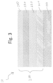
- FIG. 3 is a schematic cross-sectional view of an electrode in accordance with certain other embodiments of the present disclosure.
- FIG. 4 is a schematic cross-sectional view of an electrode in accordance with still other embodiments of the present disclosure.
- FIG. 5 is a schematic diagram of an electrode in accordance with certain embodiments of the present disclosure.
- FIG. 6 is a schematic cross-sectional view of an electrode in accordance with certain other embodiments of the present disclosure.
- FIG. 7 is a schematic cross-sectional view of an electrode in accordance with certain embodiments of the present disclosure.
- FIG. 8 is a schematic side view of an electrochemical cell in accordance with certain embodiments of the present disclosure.
- FIG. 9 is a schematic cross-section view of an electrode in accordance with certain other embodiments of the present disclosure.
- FIG. 1 there is shown one embodiment of an electrode generally represented by reference numeral 10 .
- the electrode 10 can be used in a variety of electrochemical applications.
- the electrode 10 is tolerant to current reversal. It can therefore be used in an electrochemical cell that contains hard water (e.g., hard cations). In such cases, the electrode 10 helps mitigate the buildup of scale.
- the electrode 10 can be used (e.g., is configured) to generate ozone when immersed in an electrochemical cell containing an aqueous electrolyte comprising hard water.
- the electrode 10 of the present invention comprises a substrate 100 having a coating 200 deposited thereon.
- the substrate 100 comprises a valve metal, and can optionally be formed of an alloy or other combination of two or more valve metals.
- valve metal refers to titanium, tantalum, hafnium, tungsten, aluminum, vanadium, zirconium, niobium, or any combination thereof. Titanium is often a preferred choice for the substrate 100 , based upon its cost, availability, workability and known corrosion resistance in aggressive, aqueous environments.
- the substrate 100 can be provided in any of a variety of forms, such as a plate, a perforated plate, a mesh, a tubular or cylindrical structure, or a rod-like structure.
- the substrate 100 will be a titanium plate or a titanium mesh.
- the substrate will be a carbon cloth.
- the coating 200 comprises a plurality of layers (i.e., it is a multi-layer coating).
- the coating 200 is formed by at least three layers.
- the coating 200 comprises five layers. It is to be understood, however, that the total number of layers and sublayers can vary depending upon the intended application. Thus, the number of layers and sublayers of the coating 200 noted in the examples herein is by no means limiting to the scope of the invention.
- the electrode 10 comprises, in sequence, the substrate 100 , a base layer 210 , a lower layer 220 , and a mixed oxide primary layer 230 .
- the base layer 210 is in contact with the substrate 100
- the lower layer 220 is in contact with the base layer 210
- the mixed oxide primary layer 230 is in contact with the lower layer 220 . This, however, is not required.
- the base layer 210 comprises an oxide of a valve metal.
- the valve metal of the base layer 210 can be any valve metal, and this layer can optionally comprise a combination of two or more valve metals.
- the base layer 210 i.e., the, or each, sublayer thereof
- preferably is devoid of any platinum group metal oxide, and preferably functions as a passive protective layer of the coating.
- passive we mean the layer is a non-catalytic layer of the coating.
- the base layer 210 preferably is a corrosion resistant valve metal oxide layer.
- each sublayer can have the same composition, or a different composition, as any other sublayer of the base layer.
- the base layer 210 can optionally comprise a plurality of sublayers that all have the same, or substantially the same, composition. In such cases, all the sublayers of the base layer may have the same composition.
- the base layer 210 comprises at least two sublayers, or even more than two sublayers, while optionally having less than seven sublayers. For example, it may consist of 4-6 sublayers.
- the base layer 210 (i.e., the, or each, sublayer thereof) consists or consists essentially of tantalum oxide, titanium oxide, niobium oxide, or zirconium oxide. In one example, the base layer consists or consists essentially of Ta 2 O 5-x . This, however, is by no means limiting.
- the lower layer 220 is located further from the substrate 100 than is the base layer 210 .
- the lower layer 220 comprises an oxide of a platinum group metal and/or an oxide of a precious metal.
- the precious metals are gold and silver
- the platinum group metals are platinum, ruthenium, rhodium, palladium, osmium, and iridium.
- the layer includes gold, silver, or any combination thereof.
- the lower layer 220 comprises a platinum group metal oxide
- the layer includes platinum, ruthenium, rhodium, palladium, osmium, iridium, or any combination thereof.
- the lower layer 220 i.e., the, or each, sublayer thereof
- each sublayer can have the same composition as, or a different composition from, any other sublayer of the lower layer.
- the lower layer 220 can optionally comprise a plurality of sublayers that all have the same, or substantially the same, composition. In such cases, all the sublayers of the base layer may have the same composition.
- the lower layer 220 comprises at least two sublayers, or even more than two sublayers, while optionally having less than six sublayers. For example, it may consist of five sublayers.
- the lower layer 220 i.e., the, or each, sublayer thereof
- platinum oxide such as PtO 2
- the coating 200 can optionally be devoid of any layer comprising both an oxide of a valve metal and an oxide of a platinum group metal that is located between the base layer and the lower layer.
- the lower layer is in contact with the base layer.
- the mixed oxide primary layer 230 comprises both: (i) an oxide of a platinum group metal and/or an oxide of a precious metal, and (ii) an oxide of a valve metal and/or an oxide of a group 15 metal.
- the mixed oxide primary layer 230 comprises an oxide of a platinum group metal, any one or more of the platinum group metals can be used.
- the mixed oxide primary layer 230 comprises a precious metal, gold, silver, or a combination thereof can be used.
- the mixed oxide primary layer 230 comprises an oxide of a valve metal, any one or more valve metals can be used.
- the mixed oxide primary layer 230 comprises an oxide of a group 15 metal
- the group 15 metal is bismuth or antimony.
- the oxide of the group 15 metal preferably is bismuth oxide. If desired, the mixed oxide primary layer 230 can include both bismuth and antimony.
- the mixed oxide primary layer 230 (i.e., the, or each, sublayer thereof) comprises both platinum and tantalum. This, however, is by no means required.
- each such sublayer can have the same composition as, or a different composition from, any other sublayer of the mixed oxide primary layer 230 .
- the mixed oxide primary layers 220 can optionally comprise a plurality of sublayers that all have the same, or substantially the same, composition. In such cases, all the sublayers of the mixed oxide primary layer may have the same composition.
- the mixed oxide primary layer 230 consists of a single sublayer.
- the coating 200 comprises more than three layers, such as at least four layers. Furthermore, each layer of the coating can be formed by one or more sublayers, as described above with reference to the base layer, lower layer, and mixed oxide primary layer, which are present in certain embodiments of the coating 200 .
- the plurality of layers further comprises an intermediate layer 240 .
- the intermediate layer 240 is located further from the substrate 100 than is the mixed oxide primary layer 230 .
- the intermediate layer 240 comprises an oxide of a platinum group metal and/or an oxide of a precious metal. Where the intermediate layer 240 comprises an oxide of a platinum group metal, any one or more of the platinum group metals can be used. Where the intermediate layer 240 comprises an oxide of a precious metal, gold, silver, or a combination thereof can be used.
- the intermediate layer 240 i.e., the, or each, sublayer thereof
- the intermediate layer 240 can have the same composition as, or a different composition from, the lower layer 220 .
- each such sublayer can have the same composition as, or a different composition from, any other sublayer of the intermediate layer.
- the intermediate layer 240 can optionally comprise a plurality of sublayers that all have the same, or substantially the same, composition. In such cases, all the sublayers of the intermediate layer may have the same composition.
- the intermediate layer 240 comprises (e.g., consists of) 1-5 sublayers. In some cases, it comprises at least two sublayers, or even more than two sublayers, while optionally having less than six sublayers.
- the intermediate layer 240 (i.e., the, or each, sublayer thereof) consists, or consists essentially of, a mixed oxide of platinum and tantalum, such a PtO 2 +Ta 2 O 5-x . This, however, is not limiting.
- the plurality of layers of the coating 200 comprises five layers, including the base layer 210 , the lower layer 220 , the mixed oxide primary layer 230 , and the intermediate layer 240 .
- at least three layers of the coating preferably have different compositions from one another.
- the coating includes five layers that are each contiguous to one or two layers of different composition.
- the coating 200 includes a mixed oxide upper layer 250 .
- the mixed oxide upper layer 250 is located further from the substrate 100 than is the intermediate layer 240 .
- the coating 200 has an outermost (e.g., exposed) face that is defined by the mixed oxide upper layer 250 .
- the mixed oxide upper layer 250 comprises both: (i) an oxide of a platinum group metal and/or an oxide of a precious metal, and (ii) an oxide of a valve metal and/or an oxide of a group 15 metal.
- the mixed oxide upper layer 250 comprises an oxide of a platinum group metal, any one or more of the platinum group metals can be used.
- the mixed oxide upper layer 250 comprises an oxide of a precious metal, gold, silver, or a combination thereof can be used.
- the mixed oxide upper layer 250 comprises an oxide of a valve metal, any one or more valve metals can be used.
- the mixed oxide upper layer 250 comprises an oxide of a group 15 metal, bismuth, antimony, or a combination thereof can be used.
- the oxide of the group 15 metal preferably is bismuth oxide. If desired, both bismuth and antimony can be used.
- the coating 200 includes one or more of the optional group 15 metal oxides in the mixed oxide upper layer 250 , the overvoltage of the electrode 100 can be increased, while also potentially improving the durability of the electrode 100 .
- the mixed oxide upper layer 250 can have the same composition as, or a different composition from, the mixed oxide primary layer 230 . In some non-limiting examples, all the sublayers of both the mixed oxide upper layer 250 and the mixed oxide primary layer 230 have the same, or substantially the same, composition.
- each such sublayer can have the same composition as, or a different composition from, any other sublayer of the mixed oxide upper layer.
- the mixed oxide upper layer 250 can optionally comprise a plurality of sublayers that all have the same, or substantially the same, composition. In such cases, all the sublayers of the mixed oxide upper layer 250 may have the same, composition.
- the mixed oxide upper layer 250 comprises at least two sublayers, or even more than ten sublayers, while optionally having less than 100 sublayers or less than 50 sublayers. For example, it may consist of 15-35 sublayers.
- the mixed oxide upper layer 250 (i.e., the, or each, sublayer thereof) consists, or consists essentially of, a mixed oxide of platinum and tantalum, such as PtO 2 +Ta 2 O 5-x . This, however, is by no means required.
- the coating 200 comprises the following layers: a base layer 210 comprising an oxide of tantalum; a lower layer 220 comprising an oxide of platinum; a mixed oxide primary layer 230 comprising both platinum and tantalum; an intermediate layer 240 comprising an oxide of platinum; and a mixed oxide upper layer 250 comprising both platinum and tantalum.
- the plurality of layers includes a barrier layer 260 in contact with (i.e., touching) the substrate 100 .
- a barrier layer 260 is located beneath the base layer 210 .
- the barrier layer 260 can have various compositions. Preferably, it comprises an oxide of one or more valve metals, and is devoid of any platinum group metal or precious metal. For example, it can comprise (or consist of, or consist essentially of) one or more valve metal oxides.
- the barrier layer is formed of an oxide of tantalum.
- the barrier layer 260 can optionally be provided in any embodiment of the present disclosure.
- FIG. 6 shows a preferred configuration of the coating 200 having all the layers mentioned above.
- FIG. 6 provides, in sequence: the substrate 100 ; the barrier layer 260 ; the base layer 210 ; the lower layer 220 ; the mixed oxide primary layer 230 ; the intermediate layer 240 ; and the mixed oxide upper layer 250 .
- the arrangement and compositions of the lower layer and the mixed oxide primary layer, and/or the mixed oxide primary layer and the intermediate layer, or all three of these layers contribute to the durability characteristics of the electrode 10 under current reversal or non-current reversal conditions.
- the lower layer 220 may be susceptible to eroding at high overvoltage operating conditions if not sufficiently protected.
- the mixed oxide primary layer 230 and/or the intermediate layer 240 protect the lower layer 220 against such erosion.
- each layer of the coating 200 is formed by one or more sublayers. Although certain layers are shown in the figures as being a single sublayer, the total number of sublayers in the different layers can be varied to suit a variety of applications. This makes it possible to fine-tune the overall conductivity and overpotential of the electrode 10 , as desired for a given electrochemical application.
- an electrode 10 that is tolerant to current reversal can be manufactured to operate at high anodic potentials in aqueous electrolytes to generate strong oxidants (e.g., ozone, peracetic acid, or persulfuric acid), or generate chlorate (oxidize Cr(III) to Cr(VI)).
- FIG. 7 shows a non-limiting example of the coating 200 wherein the base layer 210 , the lower layer 220 , and the mixed oxide upper layer 250 are each formed by multiple sublayers. Specifically, FIG. 7 shows the mixed oxide upper layer 250 as formed by four sublayers, while each of the base layer 210 and the lower layer 220 is formed by three sublayers. It is to be understood that this example is by no means limiting.
- the electrode 10 offers the ability to fine-tune oxygen overvoltage and oxidizing ability at low current densities such that the electrode is tolerant to current reversal.
- the present electrode composition maintains, or at least substantially maintains, its high overpotential under current reversal for long periods of time.
- the overpotential of the electrode deteriorates rapidly within a few cycles of current reversal and may lose its catalytic activity and, e.g., evolve oxygen instead of ozone.
- severe deterioration of catalyst active species may occur, such that the electrode ultimately leads to cell failure.
- high current density is required to achieve high SEP values or overpotential required for ozone generation, which in turn may lead to low current efficiency for ozone generation. This is therefore an issue related to energy consumption and durability.
- the present electrode maintains, or at least substantially maintains its initial high overpotential (e.g., does not experience a change of more than 15%, such as experiencing no change or a change of no more than 10%) throughout at least five cycles of current reversal, at least 10 cycles of current reversal, at least 100 cycles of current reversal, or even through at least 1,000 cycles of current reversal.
- initial high overpotential e.g., does not experience a change of more than 15%, such as experiencing no change or a change of no more than 10%
- the present electrode maintains, or at least substantially maintains its initial high overpotential (e.g., does not experience a change of more than 15%, such as experiencing no change or a change of no more than 10%) throughout at least five cycles of current reversal, at least 10 cycles of current reversal, at least 100 cycles of current reversal, or even through at least 1,000 cycles of current reversal.
- the present coated electrode does not lose multiple layers (e.g., it preferably retains all its layers) through any one or more numbers of current reversal cycles noted in the preceding paragraph (i.e., at least five, at least 10, at least 100, or even at least 1,000). Additionally or alternatively, the present coated electrode preferably maintains, or at least substantially maintains, its initial high overpotential through any one or more such numbers of current reversal cycles, and thus may continue to evolve O 3 during the process. In some cases, the present layered electrode composition can endure several thousand (e.g., at least 3,000, at least 5,000, or even at least 7,000) current reversal cycles.
- the invention provides a method of manufacturing an electrode 10 .
- the method involves depositing a coating 200 comprising a plurality of layers on a substrate 100 .
- the substrate 100 and coating 200 used for this method can be the same substrate and coating described above.
- the surface of the substrate 100 is degreased and cleaned before being etched or sand-blasted to create a desired surface roughness.
- the substrate 100 is then coated with a solution, as described in greater detail below.
- the coated substrate 100 is dried prior to heating in an oxygen-containing atmosphere to form oxides.
- the solution coating, drying, and thermal processing steps are repeated for each successive layer in order to form the multi-layered coating 200 .
- the total number of sublayers formed as the different layers of the coating depends on the intended application.
- the preparation of the electrode 10 for a particular application or process can be controlled and monitored by measuring the electrode potential.
- depositing the coating 200 comprises depositing a base layer 210 on (optionally directly on) the substrate 100 .
- the base layer 210 comprises an oxide of a valve metal.
- the base layer 210 preferably is devoid of any platinum group metal.
- the base layer 210 is deposited by: (a) applying one or more coats of a base solution on the substrate 100 ; and (b) drying and thermally treating each coat of the base solution in an atmosphere containing oxygen.
- the base solution comprises a salt of a valve metal, such as titanium or tantalum (e.g., TiCl 4 or TaCl 5 ).
- depositing the coating 200 comprises depositing the lower layer 220 on (optionally directly on) the base layer 210 .
- the lower layer 220 comprises an oxide of a platinum group metal and/or an oxide of a precious metal.
- the lower layer 220 preferably is devoid of any valve metal.
- the lower layer 220 is deposited by: (a) applying one or more coats of a lower solution on the substrate 100 ; and (b) drying and thermally treating each coat of the lower solution in an atmosphere containing oxygen.
- the lower solution comprises a salt of a platinum group metal, such as iridium chloride (i.e., IrCl 3 ), and/or a salt of a precious metal.
- depositing the coating 200 comprises depositing the mixed oxide primary layer 230 on the lower layer 220 .
- the mixed oxide primary layer 230 is deposited by: (a) applying one or more coats of a primary solution on the substrate 100 ; and (b) drying and thermally treating each coat of the primary solution in an atmosphere containing oxygen.
- the primary solution comprises both (i) a salt of a platinum group metal and/or a salt of a precious metal, and (ii) a salt of a valve metal and/or a salt of a group 15 metal.
- depositing the coating 200 comprises depositing at least five layers, including the base layer 210 , the lower layer 220 , and the mixed oxide primary layer 230 .
- at least three of the five layers have different compositions from one another.
- the coating deposition is conducted such that each of the noted five layers is contiguous to one or two layers of different composition.
- depositing the coating 200 further comprises depositing an intermediate layer 240 on (optionally directly on) the mixed oxide primary layer 230 .
- the intermediate layer 240 comprises an oxide of a platinum group metal and/or an oxide of a precious metal.
- the intermediate layer 240 preferably is devoid of any valve metal.
- the intermediate layer 240 is deposited by: (a) applying one or more coats of an intermediate solution on the substrate; and (b) drying and thermally treating each coat of the intermediate solution in an atmosphere containing oxygen.
- the intermediate solution comprises a salt of a platinum group metal and/or a salt of a precious metal.
- depositing the coating further involves depositing a mixed oxide upper layer 250 on (optionally directly on) the intermediate layer 240 .
- the mixed oxide upper layer 250 is deposited by: (a) applying one or more coats of an upper solution on the substrate; and (b) drying and thermally treating each coat of the upper solution in an atmosphere containing oxygen.
- the upper solution comprises both (i) a salt of a platinum group metal and/or a salt of a precious metal, and (ii) a salt of a valve metal and/or a salt of a group 15 metal.
- the coating deposition results in the coating 200 having an outermost (e.g., exposed) face that is defined by the mixed oxide upper layer 250 .
- depositing the coating 200 further comprises depositing a barrier layer 260 directly on the substrate 100 , i.e., such that the barrier layer is in contact with the substrate.
- the optional barrier layer 260 is located directly beneath (i.e., so as to contact) the base layer 210 .
- the barrier layer 260 is deposited by: (a) applying one or more coats of a barrier solution on the substrate; and (b) drying and thermally treating each coat of the barrier solution in an atmosphere containing oxygen.
- the barrier solution comprises a salt of a valve metal.
- the barrier layer deposition is conducted such that it consists of (or consists essentially of) one or more valve metal oxides, such as tantalum oxide.
- the coating deposition is conducted such that the base layer 210 comprises an oxide of tantalum; the lower layer 220 comprises an oxide of platinum; the mixed oxide primary layer 230 comprises both an oxide of platinum and an oxide of tantalum; the intermediate layer 240 comprises an oxide of platinum; and the mixed oxide upper layer comprises both an oxide of platinum and an oxide of tantalum.
- each of these layers can consist, or consist essentially of, the materials noted in this paragraph.
- the electrode 10 of the present invention when the substrate 10 is provided in plate form, either one or both of its faces can have the coating 200 deposited thereon.
- a counter electrode i.e., in a monopolar configuration
- only one face of the substrate 100 will typically have the coating 200 .
- both faces of the substrate 100 will typically have the coating 200 .
- the surface of the substrate 100 may be polished to remove any dirt, grease or oily deposits and any oxide films that may be present.
- the polishing process may involve using sandpaper or blasting the surface with sand or grit particles.
- the polished surface may then be rinsed with an organic solvent, such as acetone, to remove any residual organic contaminants. It is then preferably etched in concentrated hydrochloric acid (20%) at 85-90° C.
- Other etching solutions such as oxalic acid, sulfuric acid or hydrofluoric acid, may also be used.
- the etching process can be continued until a predetermined surface condition (e.g., topography) is obtained. While etching is preferred, it may not be done in some cases.
- the etched surface of the substrate 100 is subsequently coated with a thin layer of coating solution dissolved in either water or an organic solvent (e.g., isopropanol or n-butanol).
- a thin layer of coating solution dissolved in either water or an organic solvent (e.g., isopropanol or n-butanol).
- the etched substrate 100 is sequentially coated with multiple, thin coats of the different coating solutions. Each coat is dried and then thermally cured at a temperature between 480° C. and 510° C. for approximately 10 minutes, before an additional coat is applied.
- a small amount of concentrated hydrochloric acid can optionally be added to the coating solution, whether the solution is water or alcohol based. It is advantageous to coat the substrate 100 by applying a thin layer of diluted coating solution. This can provide uniform distribution of the metal salts in the coating 200 , thereby yielding uniform distribution of the oxides in the layer after thermal treatment.
- the coating solutions described herein may be applied to the substrate 100 by any method used to apply liquids to a solid surface. Such methods include application with a brush or roller, spray coating, dip spin and dip drain techniques, spin coating and spray coating, such as electrostatic spray coating. Moreover, combinations of these coating methods can be used, e.g., dip drain with spray application.
- the substrate 100 is allowed to dry at room temperature for several minutes and is then heated, in an atmosphere containing oxygen, to a temperature between 150° C. and 250° C., preferably between 210° C. and 230° C., for approximately ten minutes.
- a further thermal treatment is then carried out, heating the coated substrate 100 , again in an atmosphere containing oxygen, to a temperature between 450° C. and 550° C., preferably between 480° C. and 510° C., for approximately another ten minutes to completely decompose the metal salts. It is preferable to avoid higher temperatures for the thermal treatment to prevent the possible crystallization of the valve metal oxide, which can result in the formation of cracks and pores in the coating 200 .
- the electrode coating can optionally result from a manufacturing process that is devoid of any heat treatment involving temperatures of greater than 550° C.
- the coated substrate 200 is allowed to cool to room temperature before applying any additional coats of coating solution to the substrate 100 , and repeating the drying and heating steps described above for each additional coat.
- the foregoing approach allows control of both the thickness of the coating 200 and the loading (i.e., the specific amount of metal per unit area) in the coating 200 .
- the loading of the metals oxides usually expressed in terms of grams per square meter of geometric area, can be readily controlled by the concentration of the salt in the coating solutions and the number of coats applied to the substrate 100 .
- a plurality of thin coats is desirable to avoid forming powdery deposits. Multiple thin coats produce a more compact, less cracked and more durable electrode 10 .
- the number of coats for each layer may be dictated by the desired loading.
- Some embodiments of the invention provide a method of using an electrochemical cell 300 to perform an electrochemical process.
- the method involves operating the electrochemical cell 300 so as to reverse a polarity of electrical current flow through an electrode 10 immersed in electrolyte within the cell.
- the electrode 10 has a coating 200 that is durable to reversing polarity. This is in contrast to many conventional electrodes, which cannot tolerate current reversal.
- the electrochemical process generates a strong oxidant selected from the group consisting of ozone, peracetic acid, and persulfuric acid. In certain cases, the electrochemical process generates ozone.
- the basic construction of the electrochemical cell 300 can be like that of various conventional electrochemical cells. As shown in FIG. 8 , the electrochemical cell 300 comprises a housing 310 , an electrolyte 320 contained in the housing 310 , and an electrode 10 immersed in the electrolyte 320 .
- the electrolyte 320 is a liquid electrolyte, such as an aqueous electrolyte.
- the electrolyte 320 comprises hard water (e.g., hard cations).
- Hard water is generally defined as water having high mineral content, specifically a high content of calcium and magnesium carbonates. Water hardness is caused not only by compounds of calcium and magnesium, but also by a variety of other metals. For example, hard water can include elevated levels of iron, aluminum, and/or manganese. Water hardness is affected by the precise mixture of minerals dissolved in a given water supply, as well as other factors, including the temperature and pH of the water.
- the electrolyte comprises water that is moderately hard, hard, or very hard pursuant to the noted standard. In certain cases, the electrolyte comprises water that is either hard or very hard pursuant to the noted standard.
- the present method involves operating the electrode 10 while it is immersed in an electrolyte comprising water that is at least hard, or at least moderately hard, pursuant to the noted standard (and thus comprises hard cations). In such cases, reversing the polarity of electrical current flow through the electrode 10 blasts mineral scale buildup from the electrode 10 . Thus, in certain embodiments, the method involves reversing the polarity of electric current flow through the electrode and thereby removing scale buildup from the electrode.
- the electrode 10 used in the present method generally comprises a substrate 100 and a coating 200 on the substrate 100 .
- the substrate 100 can be the same as the substrate described elsewhere in the present disclosure.
- the electrochemical cell 300 comprises two electrodes, e.g., an anode and a cathode. This arrangement allows electricity to flow from one electrode 10 to the other.
- a membrane 330 can be positioned between the two electrodes 10 to partition an inside of the housing 310 into anode and cathode sides.
- the coating 200 used in the present method comprises the following plurality of layers in sequence moving outwardly from the substrate 100 : a mixed oxide primary layer 230 ; an intermediate layer 240 ; and a mixed oxide upper layer 250 .
- the mixed oxide primary layer 230 comprises both: (i) an oxide of a platinum group metal and/or an oxide of a precious metal, and (ii) an oxide of a valve metal and/or an oxide of a group 15 metal.
- the intermediate layer 240 comprises an oxide of a platinum group metal and/or an oxide of a precious metal.
- the intermediate layer 240 preferably is devoid of any valve metal oxide.
- the mixed oxide upper layer 250 comprises both: (i) an oxide of a platinum group metal and/or an oxide of a precious metal, and (ii) an oxide of a valve metal and/or an oxide of a group 15 metal.
- the coating 200 has an outermost (e.g., exposed) face that is defined by the mixed oxide upper layer 250 (see FIG. 9 ).
- the mixed oxide primary layer 230 (i.e., the, or each, sublayer thereof) can optionally have the same, or substantially the same, composition as the mixed oxide upper layer 250 (e.g., as one or more sublayers thereof). In some cases, all the sublayers of the mixed oxide primary layer and the mixed oxide upper layer have the same composition.
- the mixed oxide primary layer 230 used in the present method can have the same composition as the mixed oxide primary layer 230 described above for other embodiments of the present disclosure.
- the intermediate layer 240 used in the present method can have the same composition as the intermediate layer 240 described above for other embodiments.
- the mixed oxide upper layer 250 used in the present method can have the same composition as the mixed oxide upper layer 250 described above for other embodiments.
- the coating 200 used in the present method can include one or more additional layers.
- it can further comprise a lower layer 220 that is located closer to the substrate 100 than is the mixed oxide primary layer 230 .
- the lower layer 220 comprises an oxide of a platinum group metal and/or an oxide of a precious metal.
- the optional lower layer 220 preferably is devoid of any valve metal oxide.
- the lower layer 220 used in the present method can have the same composition as the lower layer 220 described above for other embodiments.
- the lower layer 220 (i.e., the, or each, sublayer thereof) can optionally have the same, or substantially the same, composition as the intermediate layer 240 . In some cases, all the sublayers of the lower layer and the intermediate layer have the same composition.
- the coating 200 used in the present method includes five layers, including the mixed oxide primary layer 230 , the intermediate layer 240 , and the mixed oxide upper layer 250 .
- at least three of the five layers preferably have different compositions from one another.
- each of the noted five layers is contiguous to one or two layers of different composition.
- the coating used in the present method can further comprise a base layer 210 .
- the base layer 210 is located closer to the substrate 100 than is the lower layer 220 .
- the base layer 210 comprises an oxide of a valve metal.
- the base layer 210 preferably is devoid of any platinum group metal oxide.
- the base layer 210 used in the present method can have the same composition as the base layer 210 described above for other embodiments.
- the coating used in the present method further includes a barrier layer 260 .
- the barrier layer 260 is in contact with the substrate 100 .
- the optional barrier layer 260 comprises one or more valve metal oxides, and preferably is devoid of any platinum group metal oxide.
- the barrier layer 260 used in the present method can have the same composition as the barrier layer 260 described above for other embodiments.
- the invention provides or involves an electrochemical cell 300 containing an electrolyte 320 and equipped with an electrode 10 of the nature described herein.
- anodes according to the invention can be made by a method of manufacturing that preferably includes cleaning a titanium substrate.
- the titanium substrate can be grit blasted to enhance the surface roughness and preferably by etching in acid bath to remove undesired surface oxides and other surface components.
- solutions of the desired metal compounds and compositions can be applied to the substrate, layer wise.
- current reversal stable mixed metal oxide electrodes can be prepared according to the following procedure. Five different coating solutions can all be used to make various preferred versions of the coating, as described below.
- valve metal based anodes such as solid rolled massive titanium plates, perforated plates, slitted, reticulated, titanium plates, titanium mesh and rolled titanium mesh, woven titanium wire, or screen or similar titanium plates.
- the coating can be applied on valve metals by different methods. For example, it can be painted on, dipped, sprayed, screen printed, ink-jet printed or curtain coatings baked on a titanium anode base. Other methods of application, including electrophoretic deposition or electrodeposition, may be used.
Abstract
Description
| Number of | Ta | Pt | Bi | |
| Layer | coats per | (g/m2)/ | (g/m2)/ | (g/m2)/ |
| No. | layer | coat | coat | coat |
| 1 | 4-6 | 1 | — | — |
| 2 | 5 | — | 1-5 | — |
| 3 | 1 | 1-4 | 0.01-0.25 | 0.01-0.05 |
| 4 | 1-5 | — | 1-5 | |
| 5 | 15-35 | 1-4 | 0.01-0.35 | 0.01-0.1 |
Platinum salt or precursor: Hexachloro platinic acid or any Pt salt that dissolves in butanol and acid solution
Tantalum salt or precursor: Tantalum pentachloride
Bismuth salt or precursor: Bismuth chloride
Solvent used to prepare layer 1: Butanol (100%)
Solvent used to prepare layers 3 and layer 5: ethanol:acid (95:5)
Solvent used to prepare layer 2 and 4: Butanol:acid (38:1)
Baking temperatures for layer 1: 455-475° C.
Baking temperature for layer 2 and layer 4: 450-500° C.
Baking temperature for layer 3 and layer 5: 525-575° C.
Claims (25)
Priority Applications (2)
| Application Number | Priority Date | Filing Date | Title |
|---|---|---|---|
| US16/049,284 US11668017B2 (en) | 2018-07-30 | 2018-07-30 | Current reversal tolerant multilayer material, method of making the same, use as an electrode, and use in electrochemical processes |
| US18/308,398 US20230257893A1 (en) | 2018-07-30 | 2023-04-27 | Current Reversal Tolerant Multilayer Material, Method of Making the Same, Use as an Electrode, and Use in Electrochemical Processes |
Applications Claiming Priority (1)
| Application Number | Priority Date | Filing Date | Title |
|---|---|---|---|
| US16/049,284 US11668017B2 (en) | 2018-07-30 | 2018-07-30 | Current reversal tolerant multilayer material, method of making the same, use as an electrode, and use in electrochemical processes |
Related Child Applications (1)
| Application Number | Title | Priority Date | Filing Date |
|---|---|---|---|
| US18/308,398 Continuation US20230257893A1 (en) | 2018-07-30 | 2023-04-27 | Current Reversal Tolerant Multilayer Material, Method of Making the Same, Use as an Electrode, and Use in Electrochemical Processes |
Publications (2)
| Publication Number | Publication Date |
|---|---|
| US20200032407A1 US20200032407A1 (en) | 2020-01-30 |
| US11668017B2 true US11668017B2 (en) | 2023-06-06 |
Family
ID=69179100
Family Applications (2)
| Application Number | Title | Priority Date | Filing Date |
|---|---|---|---|
| US16/049,284 Active 2039-06-08 US11668017B2 (en) | 2018-07-30 | 2018-07-30 | Current reversal tolerant multilayer material, method of making the same, use as an electrode, and use in electrochemical processes |
| US18/308,398 Pending US20230257893A1 (en) | 2018-07-30 | 2023-04-27 | Current Reversal Tolerant Multilayer Material, Method of Making the Same, Use as an Electrode, and Use in Electrochemical Processes |
Family Applications After (1)
| Application Number | Title | Priority Date | Filing Date |
|---|---|---|---|
| US18/308,398 Pending US20230257893A1 (en) | 2018-07-30 | 2023-04-27 | Current Reversal Tolerant Multilayer Material, Method of Making the Same, Use as an Electrode, and Use in Electrochemical Processes |
Country Status (1)
| Country | Link |
|---|---|
| US (2) | US11668017B2 (en) |
Citations (108)
| Publication number | Priority date | Publication date | Assignee | Title |
|---|---|---|---|---|
| US2972572A (en) | 1958-12-09 | 1961-02-21 | Westinghouse Electric Corp | Acid copper addition agent |
| US3234110A (en) | 1959-02-06 | 1966-02-08 | Amalgamated Curacao Patents Co | Electrode and method of making same |
| US3265526A (en) | 1961-07-06 | 1966-08-09 | Amalgamated Curacao Patents Co | Method of chemically plating base layers with precious metals of the platinum group |
| US3267010A (en) | 1962-04-16 | 1966-08-16 | Udylite Corp | Electrodeposition of copper from acidic baths |
| US3293167A (en) * | 1962-10-08 | 1966-12-20 | Engelhard Ind Inc | Platinum bismuth alloy coated electrodes |
| GB1147442A (en) | 1965-05-12 | 1969-04-02 | Henri Bernard Beer | Improvements in or relating to electrodes for electrolysis |
| GB1195871A (en) | 1967-02-10 | 1970-06-24 | Chemnor Ag | Improvements in or relating to the Manufacture of Electrodes. |
| US3616445A (en) | 1967-12-14 | 1971-10-26 | Electronor Corp | Titanium or tantalum base electrodes with applied titanium or tantalum oxide face activated with noble metals or noble metal oxides |
| US3657102A (en) | 1968-12-23 | 1972-04-18 | Engelhard Min & Chem | Electrolytic anode |
| US3711397A (en) | 1970-11-02 | 1973-01-16 | Ppg Industries Inc | Electrode and process for making same |
| US3711385A (en) | 1970-09-25 | 1973-01-16 | Chemnor Corp | Electrode having platinum metal oxide coating thereon,and method of use thereof |
| US3718550A (en) | 1969-12-05 | 1973-02-27 | Alusuisse | Process for the electrolytic production of aluminum |
| US3751296A (en) | 1967-02-10 | 1973-08-07 | Chemnor Ag | Electrode and coating therefor |
| US3773554A (en) | 1970-03-18 | 1973-11-20 | Ici Ltd | Electrodes for electrochemical processes |
| US3778307A (en) | 1967-02-10 | 1973-12-11 | Chemnor Corp | Electrode and coating therefor |
| GB1344540A (en) | 1970-03-23 | 1974-01-23 | Electronor Corp | Electrodes for electrochemical process |
| US3788968A (en) | 1971-01-08 | 1974-01-29 | Metallgesellschaft Ag | Layered electrode |
| US3840443A (en) | 1967-02-10 | 1974-10-08 | Chemnor Corp | Method of making an electrode having a coating comprising a platinum metal oxide |
| US3869312A (en) | 1971-03-18 | 1975-03-04 | Ici Ltd | Electrodes and electrochemical processes |
| US3875043A (en) | 1973-04-19 | 1975-04-01 | Electronor Corp | Electrodes with multicomponent coatings |
| US3878083A (en) | 1972-05-18 | 1975-04-15 | Electronor Corp | Anode for oxygen evolution |
| US3882002A (en) | 1974-08-02 | 1975-05-06 | Hooker Chemicals Plastics Corp | Anode for electrolytic processes |
| US3926751A (en) | 1972-05-18 | 1975-12-16 | Electronor Corp | Method of electrowinning metals |
| US3933616A (en) | 1967-02-10 | 1976-01-20 | Chemnor Corporation | Coating of protected electrocatalytic material on an electrode |
| US3940323A (en) | 1974-08-02 | 1976-02-24 | Hooker Chemicals & Plastics Corporation | Anode for electrolytic processes |
| US3950240A (en) | 1975-05-05 | 1976-04-13 | Hooker Chemicals & Plastics Corporation | Anode for electrolytic processes |
| US4005003A (en) | 1975-04-15 | 1977-01-25 | Olin Corporation | Multi-component metal electrode |
| US4039400A (en) | 1974-10-29 | 1977-08-02 | Marston Excelsior Limited | Method of forming electrodes |
| US4086157A (en) | 1974-01-31 | 1978-04-25 | C. Conradty | Electrode for electrochemical processes |
| GB2007712A (en) | 1977-11-09 | 1979-05-23 | Noranda Mines Ltd | Stable electrode for electrochemical applications |
| US4272354A (en) | 1978-03-28 | 1981-06-09 | Diamond Shamrock Technologies, S.A. | Electrodes for electrolytic processes |
| US4310391A (en) | 1979-12-21 | 1982-01-12 | Bell Telephone Laboratories, Incorporated | Electrolytic gold plating |
| US4318795A (en) | 1967-12-14 | 1982-03-09 | Diamond Shamrock Technologies S.A. | Valve metal electrode with valve metal oxide semi-conductor face and methods of carrying out electrolysis reactions |
| US4411761A (en) | 1980-06-28 | 1983-10-25 | Basf Aktiengesellschaft | Spinel-containing electrode and process for its production |
| US4426262A (en) | 1982-04-29 | 1984-01-17 | Engelhard Corporation | Promotion of Pt-Ir catalytic electrodes with lead, tantalum, ruthenium and oxygen |
| US4437948A (en) | 1981-10-16 | 1984-03-20 | Bell Telephone Laboratories, Incorporated | Copper plating procedure |
| US4469564A (en) | 1982-08-11 | 1984-09-04 | At&T Bell Laboratories | Copper electroplating process |
| US4517068A (en) | 1981-12-28 | 1985-05-14 | Eltech Systems Corporation | Electrocatalytic electrode |
| US4528084A (en) | 1980-08-18 | 1985-07-09 | Eltech Systems Corporation | Electrode with electrocatalytic surface |
| US4530742A (en) | 1983-01-26 | 1985-07-23 | Ppg Industries, Inc. | Electrode and method of preparing same |
| US4585540A (en) | 1984-09-13 | 1986-04-29 | Eltech Systems Corporation | Composite catalytic material particularly for electrolysis electrodes and method of manufacture |
| US4589969A (en) | 1984-10-12 | 1986-05-20 | Yurkov Leonid I | Electrode for electrolysis of solutions of electrolytes and process for producing same |
| EP0090425B1 (en) | 1982-03-31 | 1987-10-07 | Ishifuku Metal Industry Co., Ltd. | Electrolysis electrode and production method thereof |
| US5006321A (en) | 1989-01-04 | 1991-04-09 | The Perkin-Elmer Corporation | Thermal spray method for producing glass mold plungers |
| US5098546A (en) | 1989-12-22 | 1992-03-24 | Tdk Corporation | Oxygen-generating electrode |
| JPH0499294A (en) | 1990-08-09 | 1992-03-31 | Daiso Co Ltd | Oxygen generating anode and its production |
| EP0495468A2 (en) | 1991-01-16 | 1992-07-22 | Circuit Foil U.S.A. Incorporated | Method of producing treated copper foil, products thereof and electrolyte useful in such method |
| US5156726A (en) | 1987-03-24 | 1992-10-20 | Tdk Corporation | Oxygen-generating electrode and method for the preparation thereof |
| US5167788A (en) | 1989-06-30 | 1992-12-01 | Eltech Systems Corporation | Metal substrate of improved surface morphology |
| EP0538955A1 (en) | 1991-10-21 | 1993-04-28 | Magneto-Chemie B.V. | Anodes with extended service life and methods for their manufacturing |
| US5262040A (en) | 1989-06-30 | 1993-11-16 | Eltech Systems Corporation | Method of using a metal substrate of improved surface morphology |
| US5294317A (en) | 1992-03-11 | 1994-03-15 | Tdk Corporation | Oxygen generating electrode |
| EP0598517A1 (en) | 1992-11-06 | 1994-05-25 | Permelec Electrode Ltd | Production process of metallic foil by electrolysis |
| US5324407A (en) | 1989-06-30 | 1994-06-28 | Eltech Systems Corporation | Substrate of improved plasma sprayed surface morphology and its use as an electrode in an electrolytic cell |
| US5334293A (en) | 1990-08-31 | 1994-08-02 | Imperial Chemical Industries Public Limited Company | Electrode comprising a coated valve metal substrate |
| US5407556A (en) | 1992-11-11 | 1995-04-18 | Permelec Electrode Ltd. | Process of producing metallic foil by electrolysis |
| US5489368A (en) | 1992-01-28 | 1996-02-06 | Permelec Electrode, Ltd. | Insoluble electrode structural material |
| US5531875A (en) | 1993-08-24 | 1996-07-02 | Permelec Electrode Co., Ltd. | Electrode substrate for electrolysis and production method thereof |
| JPH09125291A (en) | 1995-11-01 | 1997-05-13 | Permelec Electrode Ltd | Electrode substrate |
| US5783050A (en) | 1995-05-04 | 1998-07-21 | Eltech Systems Corporation | Electrode for electrochemical cell |
| US5908540A (en) | 1997-08-07 | 1999-06-01 | International Business Machines Corporation | Copper anode assembly for stabilizing organic additives in electroplating of copper |
| US6071570A (en) | 1989-06-30 | 2000-06-06 | Eltech Systems Corporation | Electrodes of improved service life |
| US6103093A (en) | 1997-09-17 | 2000-08-15 | De Nora S.P.A. | Anode for oxygen evolution in electrolytes containing manganese and fluorides |
| EP0867527B1 (en) | 1997-02-27 | 2001-03-21 | Aragonesas Industrias Y Energia, S.A. | Electrode with catalytic coating for electrochemical processes and manufacture thereof |
| US6217729B1 (en) * | 1999-04-08 | 2001-04-17 | United States Filter Corporation | Anode formulation and methods of manufacture |
| US6231731B1 (en) | 1998-04-24 | 2001-05-15 | Tdk Corporation | Electrolyzing electrode and process for the production thereof |
| US6251254B1 (en) | 1998-09-30 | 2001-06-26 | Permelec Electrode Ltd. | Electrode for chromium plating |
| US6352625B1 (en) | 1998-03-02 | 2002-03-05 | Atofina | Specific cathode, used for preparing an alkaline metal chlorate and method for making same |
| US20020139689A1 (en) | 2001-02-01 | 2002-10-03 | Vadim Zolotarsky | Electrode coating and method of use in a reverse polarity electrolytic cell |
| US6527924B1 (en) | 1999-08-20 | 2003-03-04 | Atofina | Cathode for electrolyzing aqueous solutions |
| US6527939B1 (en) | 1999-06-28 | 2003-03-04 | Eltech Systems Corporation | Method of producing copper foil with an anode having multiple coating layers |
| US6572758B2 (en) | 2001-02-06 | 2003-06-03 | United States Filter Corporation | Electrode coating and method of use and preparation thereof |
| US20040031692A1 (en) | 1999-06-28 | 2004-02-19 | Kenneth Hardee | Coatings for the inhibition of undesirable oxidation in an electrochemical cell |
| US6802948B2 (en) | 1998-05-06 | 2004-10-12 | Eltech Systems Corporation | Copper electrowinning |
| US20050211553A1 (en) | 2002-05-24 | 2005-09-29 | Corrado Mojana | Electrode for gas evolution and method for its production |
| US7156962B2 (en) | 2001-06-21 | 2007-01-02 | Sanyo Electric Co., Ltd. | Electrolyzing electrode and production method therefor and electrolysis method using electrolyzing electrode and electrolysis solution producing device |
| US20070000774A1 (en) | 2005-06-29 | 2007-01-04 | Oleh Weres | Electrode with surface comprising oxides of titanium and bismuth and water purification process using this electrode |
| US7258778B2 (en) | 2003-03-24 | 2007-08-21 | Eltech Systems Corporation | Electrocatalytic coating with lower platinum group metals and electrode made therefrom |
| US7378005B2 (en) | 2004-08-31 | 2008-05-27 | Sanyo Electric Co., Ltd. | Electrode for electrolysis and method of manufacturing electrode for electrolysis |
| US7566389B2 (en) | 2003-10-08 | 2009-07-28 | Akzo Nobel N.V. | Electrode |
| US20090288958A1 (en) | 2008-05-24 | 2009-11-26 | Phelps Dodge Corporation | Electrochemically active composition, methods of making, and uses thereof |
| US7632535B2 (en) | 2003-05-07 | 2009-12-15 | De Nora Tech, Inc. | Smooth surface morphology chlorate anode coating |
| US20100096260A1 (en) | 2008-10-16 | 2010-04-22 | Finnchem Usa Inc | Water chlorinator having dual functioning electrodes |
| US20100187122A1 (en) | 2007-04-05 | 2010-07-29 | Vadim Zolotarsky | Method and system of electrolytic treatment |
| US7811426B2 (en) * | 2006-05-09 | 2010-10-12 | Daiki Ataka Engineering Co., Ltd. | Oxygen evolution electrode |
| US7884044B2 (en) | 2004-09-01 | 2011-02-08 | Eltech Systems Corporation | Pd-containing coatings for low chlorine overvoltage |
| US7976989B2 (en) | 2003-10-29 | 2011-07-12 | Umicore Ag & Co. Kg | Precious metal oxide catalyst for water electrolysis |
| US7985327B2 (en) | 2006-06-19 | 2011-07-26 | Clarizon Limited | Electrode, method of manufacture and use thereof |
| US8002955B2 (en) | 2003-12-04 | 2011-08-23 | Clenox, L.L.C. | Cylindrical electrolysis cell |
| US20110226634A1 (en) | 2009-06-19 | 2011-09-22 | Sai Bhavaraju | Bismuth metal oxide pyrochlores as electrode materials for electrolytic ozone and perchlorate generation |
| US20110290642A1 (en) * | 2010-05-25 | 2011-12-01 | Permelec Electrode Ltd. | Anode for electrolysis and manufacturing method thereof |
| US8070924B2 (en) | 2007-03-23 | 2011-12-06 | Permelec Electrode Ltd. | Electrode for generation of hydrogen |
| US20120085571A1 (en) * | 2010-10-08 | 2012-04-12 | Water Star, Inc. | Multi-layer mixed metal oxide electrode and method for making same |
| US20120091007A1 (en) | 2009-05-07 | 2012-04-19 | Daiso Co., Ltd. | Anode for oxygen generation |
| US20120125785A1 (en) * | 2009-07-28 | 2012-05-24 | Industrie De Nora S.P.A. | Cathode for Electrolytic Processes |
| US20130087450A1 (en) | 2010-06-17 | 2013-04-11 | Industrie De Nora S.P.A. | Electrode for electrochlorination |
| US20130175165A1 (en) | 2010-09-17 | 2013-07-11 | Tanaka Kikinzoku Kogyo K.K. | Electrolytic electrode, anode for electrolytic production of ozone, anode for electrolytic production of persulfuric acid and anode for electrolytic oxidation of chromium |
| US20140353168A1 (en) | 2012-02-07 | 2014-12-04 | Industrie De Nora S.P.A. | Electrode for electrochemical abatement of chemical oxygen demand of industrial wastes |
| US20150041410A1 (en) | 2013-08-07 | 2015-02-12 | Water Star, Inc. | Point of use electrolysis system |
| US20150096896A1 (en) | 2012-05-21 | 2015-04-09 | Industrie De Nora S.P.A. | Electrode for evolution of gaseous products and method of manufacturing thereof |
| US20150136591A1 (en) | 2011-12-21 | 2015-05-21 | Global Water Holding, Llc | Electrolytic cell with advanced oxidation process and electro catalytic paddle electrode |
| US20150144499A1 (en) * | 2012-06-18 | 2015-05-28 | Industrie De Nora S.P.A. | Electrolytic cell equipped with concentric electrode pairs |
| US9090981B2 (en) | 2011-05-03 | 2015-07-28 | Industrie De Nora S.P.A. | Electrode for electrolytic processes and method of manufacturing thereof |
| US20150308004A1 (en) | 2012-11-29 | 2015-10-29 | Industrie De Nora S.P.A. | Cathode for electrolytic evolution of hydrogen |
| US20160002076A1 (en) * | 2013-03-15 | 2016-01-07 | Hydronovation, Inc. | Electrochemical water softening system |
| US20160251763A1 (en) | 2013-12-03 | 2016-09-01 | Industrie De Nora S.P.A. | Electrolytic Cell Equipped With Concentric Electrode Pairs |
| US20170267552A1 (en) * | 2016-03-15 | 2017-09-21 | Elchemtech Co., Ltd. | 3-dimensional porous mono-polar electrode body, electric sterilization filter including 3-dimensional porous mono-polar electrode body, and water treatment method using 3-dimensional porous mono-polar electrode body |
| US20200148559A1 (en) * | 2017-07-12 | 2020-05-14 | Axine Water Technologies Inc. | Method of operating a wastewater treatment system |
-
2018
- 2018-07-30 US US16/049,284 patent/US11668017B2/en active Active
-
2023
- 2023-04-27 US US18/308,398 patent/US20230257893A1/en active Pending
Patent Citations (118)
| Publication number | Priority date | Publication date | Assignee | Title |
|---|---|---|---|---|
| US2972572A (en) | 1958-12-09 | 1961-02-21 | Westinghouse Electric Corp | Acid copper addition agent |
| US3234110A (en) | 1959-02-06 | 1966-02-08 | Amalgamated Curacao Patents Co | Electrode and method of making same |
| US3265526A (en) | 1961-07-06 | 1966-08-09 | Amalgamated Curacao Patents Co | Method of chemically plating base layers with precious metals of the platinum group |
| US3267010A (en) | 1962-04-16 | 1966-08-16 | Udylite Corp | Electrodeposition of copper from acidic baths |
| US3293167A (en) * | 1962-10-08 | 1966-12-20 | Engelhard Ind Inc | Platinum bismuth alloy coated electrodes |
| GB1147442A (en) | 1965-05-12 | 1969-04-02 | Henri Bernard Beer | Improvements in or relating to electrodes for electrolysis |
| US3632498A (en) | 1967-02-10 | 1972-01-04 | Chemnor Ag | Electrode and coating therefor |
| US3840443A (en) | 1967-02-10 | 1974-10-08 | Chemnor Corp | Method of making an electrode having a coating comprising a platinum metal oxide |
| GB1195871A (en) | 1967-02-10 | 1970-06-24 | Chemnor Ag | Improvements in or relating to the Manufacture of Electrodes. |
| US3751296A (en) | 1967-02-10 | 1973-08-07 | Chemnor Ag | Electrode and coating therefor |
| US3778307A (en) | 1967-02-10 | 1973-12-11 | Chemnor Corp | Electrode and coating therefor |
| US3933616A (en) | 1967-02-10 | 1976-01-20 | Chemnor Corporation | Coating of protected electrocatalytic material on an electrode |
| US3616445A (en) | 1967-12-14 | 1971-10-26 | Electronor Corp | Titanium or tantalum base electrodes with applied titanium or tantalum oxide face activated with noble metals or noble metal oxides |
| US4318795A (en) | 1967-12-14 | 1982-03-09 | Diamond Shamrock Technologies S.A. | Valve metal electrode with valve metal oxide semi-conductor face and methods of carrying out electrolysis reactions |
| US3948751A (en) | 1967-12-14 | 1976-04-06 | Oronzio De Nora Impianti Elettrochimici S.P.A. | Valve metal electrode with valve metal oxide semi-conductive face |
| US3657102A (en) | 1968-12-23 | 1972-04-18 | Engelhard Min & Chem | Electrolytic anode |
| US3718550A (en) | 1969-12-05 | 1973-02-27 | Alusuisse | Process for the electrolytic production of aluminum |
| US3773554A (en) | 1970-03-18 | 1973-11-20 | Ici Ltd | Electrodes for electrochemical processes |
| GB1344540A (en) | 1970-03-23 | 1974-01-23 | Electronor Corp | Electrodes for electrochemical process |
| US3711385A (en) | 1970-09-25 | 1973-01-16 | Chemnor Corp | Electrode having platinum metal oxide coating thereon,and method of use thereof |
| US3711397A (en) | 1970-11-02 | 1973-01-16 | Ppg Industries Inc | Electrode and process for making same |
| US3788968A (en) | 1971-01-08 | 1974-01-29 | Metallgesellschaft Ag | Layered electrode |
| US3869312A (en) | 1971-03-18 | 1975-03-04 | Ici Ltd | Electrodes and electrochemical processes |
| US3878083A (en) | 1972-05-18 | 1975-04-15 | Electronor Corp | Anode for oxygen evolution |
| US3926751A (en) | 1972-05-18 | 1975-12-16 | Electronor Corp | Method of electrowinning metals |
| US3875043A (en) | 1973-04-19 | 1975-04-01 | Electronor Corp | Electrodes with multicomponent coatings |
| US4086157A (en) | 1974-01-31 | 1978-04-25 | C. Conradty | Electrode for electrochemical processes |
| US3882002A (en) | 1974-08-02 | 1975-05-06 | Hooker Chemicals Plastics Corp | Anode for electrolytic processes |
| US3940323A (en) | 1974-08-02 | 1976-02-24 | Hooker Chemicals & Plastics Corporation | Anode for electrolytic processes |
| US4039400A (en) | 1974-10-29 | 1977-08-02 | Marston Excelsior Limited | Method of forming electrodes |
| US4005003A (en) | 1975-04-15 | 1977-01-25 | Olin Corporation | Multi-component metal electrode |
| US3950240A (en) | 1975-05-05 | 1976-04-13 | Hooker Chemicals & Plastics Corporation | Anode for electrolytic processes |
| CA1088026A (en) | 1977-11-09 | 1980-10-21 | Raouf O. Loutfy | Stable electrode for electrochemical applications |
| GB2007712A (en) | 1977-11-09 | 1979-05-23 | Noranda Mines Ltd | Stable electrode for electrochemical applications |
| US4272354A (en) | 1978-03-28 | 1981-06-09 | Diamond Shamrock Technologies, S.A. | Electrodes for electrolytic processes |
| US4310391A (en) | 1979-12-21 | 1982-01-12 | Bell Telephone Laboratories, Incorporated | Electrolytic gold plating |
| US4411761A (en) | 1980-06-28 | 1983-10-25 | Basf Aktiengesellschaft | Spinel-containing electrode and process for its production |
| US4528084A (en) | 1980-08-18 | 1985-07-09 | Eltech Systems Corporation | Electrode with electrocatalytic surface |
| US4437948A (en) | 1981-10-16 | 1984-03-20 | Bell Telephone Laboratories, Incorporated | Copper plating procedure |
| US4517068A (en) | 1981-12-28 | 1985-05-14 | Eltech Systems Corporation | Electrocatalytic electrode |
| EP0090425B1 (en) | 1982-03-31 | 1987-10-07 | Ishifuku Metal Industry Co., Ltd. | Electrolysis electrode and production method thereof |
| US4426262A (en) | 1982-04-29 | 1984-01-17 | Engelhard Corporation | Promotion of Pt-Ir catalytic electrodes with lead, tantalum, ruthenium and oxygen |
| US4469564A (en) | 1982-08-11 | 1984-09-04 | At&T Bell Laboratories | Copper electroplating process |
| US4530742A (en) | 1983-01-26 | 1985-07-23 | Ppg Industries, Inc. | Electrode and method of preparing same |
| US4585540A (en) | 1984-09-13 | 1986-04-29 | Eltech Systems Corporation | Composite catalytic material particularly for electrolysis electrodes and method of manufacture |
| US4589969A (en) | 1984-10-12 | 1986-05-20 | Yurkov Leonid I | Electrode for electrolysis of solutions of electrolytes and process for producing same |
| US5156726A (en) | 1987-03-24 | 1992-10-20 | Tdk Corporation | Oxygen-generating electrode and method for the preparation thereof |
| US5006321A (en) | 1989-01-04 | 1991-04-09 | The Perkin-Elmer Corporation | Thermal spray method for producing glass mold plungers |
| US5167788A (en) | 1989-06-30 | 1992-12-01 | Eltech Systems Corporation | Metal substrate of improved surface morphology |
| US5262040A (en) | 1989-06-30 | 1993-11-16 | Eltech Systems Corporation | Method of using a metal substrate of improved surface morphology |
| US6071570A (en) | 1989-06-30 | 2000-06-06 | Eltech Systems Corporation | Electrodes of improved service life |
| US5324407A (en) | 1989-06-30 | 1994-06-28 | Eltech Systems Corporation | Substrate of improved plasma sprayed surface morphology and its use as an electrode in an electrolytic cell |
| US5098546A (en) | 1989-12-22 | 1992-03-24 | Tdk Corporation | Oxygen-generating electrode |
| JPH0499294A (en) | 1990-08-09 | 1992-03-31 | Daiso Co Ltd | Oxygen generating anode and its production |
| US5334293A (en) | 1990-08-31 | 1994-08-02 | Imperial Chemical Industries Public Limited Company | Electrode comprising a coated valve metal substrate |
| EP0495468A2 (en) | 1991-01-16 | 1992-07-22 | Circuit Foil U.S.A. Incorporated | Method of producing treated copper foil, products thereof and electrolyte useful in such method |
| EP0538955A1 (en) | 1991-10-21 | 1993-04-28 | Magneto-Chemie B.V. | Anodes with extended service life and methods for their manufacturing |
| US5489368A (en) | 1992-01-28 | 1996-02-06 | Permelec Electrode, Ltd. | Insoluble electrode structural material |
| US5294317A (en) | 1992-03-11 | 1994-03-15 | Tdk Corporation | Oxygen generating electrode |
| EP0598517A1 (en) | 1992-11-06 | 1994-05-25 | Permelec Electrode Ltd | Production process of metallic foil by electrolysis |
| US5407556A (en) | 1992-11-11 | 1995-04-18 | Permelec Electrode Ltd. | Process of producing metallic foil by electrolysis |
| US5531875A (en) | 1993-08-24 | 1996-07-02 | Permelec Electrode Co., Ltd. | Electrode substrate for electrolysis and production method thereof |
| US5783050A (en) | 1995-05-04 | 1998-07-21 | Eltech Systems Corporation | Electrode for electrochemical cell |
| JPH09125291A (en) | 1995-11-01 | 1997-05-13 | Permelec Electrode Ltd | Electrode substrate |
| EP0867527B1 (en) | 1997-02-27 | 2001-03-21 | Aragonesas Industrias Y Energia, S.A. | Electrode with catalytic coating for electrochemical processes and manufacture thereof |
| US5908540A (en) | 1997-08-07 | 1999-06-01 | International Business Machines Corporation | Copper anode assembly for stabilizing organic additives in electroplating of copper |
| US6103093A (en) | 1997-09-17 | 2000-08-15 | De Nora S.P.A. | Anode for oxygen evolution in electrolytes containing manganese and fluorides |
| US6352625B1 (en) | 1998-03-02 | 2002-03-05 | Atofina | Specific cathode, used for preparing an alkaline metal chlorate and method for making same |
| US6231731B1 (en) | 1998-04-24 | 2001-05-15 | Tdk Corporation | Electrolyzing electrode and process for the production thereof |
| US6802948B2 (en) | 1998-05-06 | 2004-10-12 | Eltech Systems Corporation | Copper electrowinning |
| US6251254B1 (en) | 1998-09-30 | 2001-06-26 | Permelec Electrode Ltd. | Electrode for chromium plating |
| US6217729B1 (en) * | 1999-04-08 | 2001-04-17 | United States Filter Corporation | Anode formulation and methods of manufacture |
| US6527939B1 (en) | 1999-06-28 | 2003-03-04 | Eltech Systems Corporation | Method of producing copper foil with an anode having multiple coating layers |
| US20040031692A1 (en) | 1999-06-28 | 2004-02-19 | Kenneth Hardee | Coatings for the inhibition of undesirable oxidation in an electrochemical cell |
| US7247229B2 (en) | 1999-06-28 | 2007-07-24 | Eltech Systems Corporation | Coatings for the inhibition of undesirable oxidation in an electrochemical cell |
| US6527924B1 (en) | 1999-08-20 | 2003-03-04 | Atofina | Cathode for electrolyzing aqueous solutions |
| US20020139689A1 (en) | 2001-02-01 | 2002-10-03 | Vadim Zolotarsky | Electrode coating and method of use in a reverse polarity electrolytic cell |
| US6572758B2 (en) | 2001-02-06 | 2003-06-03 | United States Filter Corporation | Electrode coating and method of use and preparation thereof |
| US7156962B2 (en) | 2001-06-21 | 2007-01-02 | Sanyo Electric Co., Ltd. | Electrolyzing electrode and production method therefor and electrolysis method using electrolyzing electrode and electrolysis solution producing device |
| US20050211553A1 (en) | 2002-05-24 | 2005-09-29 | Corrado Mojana | Electrode for gas evolution and method for its production |
| US7815781B2 (en) | 2002-05-24 | 2010-10-19 | De Nora Elettrodi S.P.A | Electrode for gas evolution and method for its production |
| US7258778B2 (en) | 2003-03-24 | 2007-08-21 | Eltech Systems Corporation | Electrocatalytic coating with lower platinum group metals and electrode made therefrom |
| US20100044219A1 (en) | 2003-05-07 | 2010-02-25 | Eltech Systems Corporation | Smooth Surface Morphology Chlorate Anode Coating |
| US7632535B2 (en) | 2003-05-07 | 2009-12-15 | De Nora Tech, Inc. | Smooth surface morphology chlorate anode coating |
| US7566389B2 (en) | 2003-10-08 | 2009-07-28 | Akzo Nobel N.V. | Electrode |
| US7976989B2 (en) | 2003-10-29 | 2011-07-12 | Umicore Ag & Co. Kg | Precious metal oxide catalyst for water electrolysis |
| US8002955B2 (en) | 2003-12-04 | 2011-08-23 | Clenox, L.L.C. | Cylindrical electrolysis cell |
| US7378005B2 (en) | 2004-08-31 | 2008-05-27 | Sanyo Electric Co., Ltd. | Electrode for electrolysis and method of manufacturing electrode for electrolysis |
| US7884044B2 (en) | 2004-09-01 | 2011-02-08 | Eltech Systems Corporation | Pd-containing coatings for low chlorine overvoltage |
| US7494583B2 (en) | 2005-06-29 | 2009-02-24 | Oleh Weres | Electrode with surface comprising oxides of titanium and bismuth and water purification process using this electrode |
| US20070000774A1 (en) | 2005-06-29 | 2007-01-04 | Oleh Weres | Electrode with surface comprising oxides of titanium and bismuth and water purification process using this electrode |
| US7811426B2 (en) * | 2006-05-09 | 2010-10-12 | Daiki Ataka Engineering Co., Ltd. | Oxygen evolution electrode |
| US7985327B2 (en) | 2006-06-19 | 2011-07-26 | Clarizon Limited | Electrode, method of manufacture and use thereof |
| US8070924B2 (en) | 2007-03-23 | 2011-12-06 | Permelec Electrode Ltd. | Electrode for generation of hydrogen |
| US20100187122A1 (en) | 2007-04-05 | 2010-07-29 | Vadim Zolotarsky | Method and system of electrolytic treatment |
| US20090288958A1 (en) | 2008-05-24 | 2009-11-26 | Phelps Dodge Corporation | Electrochemically active composition, methods of making, and uses thereof |
| US20100096260A1 (en) | 2008-10-16 | 2010-04-22 | Finnchem Usa Inc | Water chlorinator having dual functioning electrodes |
| US8075751B2 (en) | 2008-10-16 | 2011-12-13 | Finnchem Usa, Inc. | Water chlorinator having dual functioning electrodes |
| US20120091007A1 (en) | 2009-05-07 | 2012-04-19 | Daiso Co., Ltd. | Anode for oxygen generation |
| US20110226634A1 (en) | 2009-06-19 | 2011-09-22 | Sai Bhavaraju | Bismuth metal oxide pyrochlores as electrode materials for electrolytic ozone and perchlorate generation |
| US20120125785A1 (en) * | 2009-07-28 | 2012-05-24 | Industrie De Nora S.P.A. | Cathode for Electrolytic Processes |
| US20110290642A1 (en) * | 2010-05-25 | 2011-12-01 | Permelec Electrode Ltd. | Anode for electrolysis and manufacturing method thereof |
| US20130087450A1 (en) | 2010-06-17 | 2013-04-11 | Industrie De Nora S.P.A. | Electrode for electrochlorination |
| US20130175165A1 (en) | 2010-09-17 | 2013-07-11 | Tanaka Kikinzoku Kogyo K.K. | Electrolytic electrode, anode for electrolytic production of ozone, anode for electrolytic production of persulfuric acid and anode for electrolytic oxidation of chromium |
| US9353448B2 (en) | 2010-09-17 | 2016-05-31 | Tanaka Kikinzoku Kogyo K.K. | Electrolytic electrode, anode for electrolytic production of ozone, anode for electrolytic production of persulfuric acid and anode for electrolytic oxidation of chromium |
| US20120085571A1 (en) * | 2010-10-08 | 2012-04-12 | Water Star, Inc. | Multi-layer mixed metal oxide electrode and method for making same |
| US9090981B2 (en) | 2011-05-03 | 2015-07-28 | Industrie De Nora S.P.A. | Electrode for electrolytic processes and method of manufacturing thereof |
| US20150136591A1 (en) | 2011-12-21 | 2015-05-21 | Global Water Holding, Llc | Electrolytic cell with advanced oxidation process and electro catalytic paddle electrode |
| US20140353168A1 (en) | 2012-02-07 | 2014-12-04 | Industrie De Nora S.P.A. | Electrode for electrochemical abatement of chemical oxygen demand of industrial wastes |
| US20150096896A1 (en) | 2012-05-21 | 2015-04-09 | Industrie De Nora S.P.A. | Electrode for evolution of gaseous products and method of manufacturing thereof |
| US20150144499A1 (en) * | 2012-06-18 | 2015-05-28 | Industrie De Nora S.P.A. | Electrolytic cell equipped with concentric electrode pairs |
| US9222181B2 (en) | 2012-06-18 | 2015-12-29 | Industrie De Nora S.P.A. | Electrolytic cell equipped with concentric electrode pairs |
| US20150308004A1 (en) | 2012-11-29 | 2015-10-29 | Industrie De Nora S.P.A. | Cathode for electrolytic evolution of hydrogen |
| US20160002076A1 (en) * | 2013-03-15 | 2016-01-07 | Hydronovation, Inc. | Electrochemical water softening system |
| US20150041410A1 (en) | 2013-08-07 | 2015-02-12 | Water Star, Inc. | Point of use electrolysis system |
| US20160251763A1 (en) | 2013-12-03 | 2016-09-01 | Industrie De Nora S.P.A. | Electrolytic Cell Equipped With Concentric Electrode Pairs |
| US20170267552A1 (en) * | 2016-03-15 | 2017-09-21 | Elchemtech Co., Ltd. | 3-dimensional porous mono-polar electrode body, electric sterilization filter including 3-dimensional porous mono-polar electrode body, and water treatment method using 3-dimensional porous mono-polar electrode body |
| US20200148559A1 (en) * | 2017-07-12 | 2020-05-14 | Axine Water Technologies Inc. | Method of operating a wastewater treatment system |
Non-Patent Citations (14)
| Title |
|---|
| Awad et al ("Ozone electrogeneration at a high current efficiency using a tantalum oxide-platinum composite electrode", Electrochemistry Communications, vol. 8, Issue 8, Aug. 2006, pp. 1263-1269) (Year: 2006). * |
| Awad et al., "Ozone electrogeneration at a high current efficiency using a tantalum oxide-platinum composite electrode," Electrochemistry Communications, vol. 8, 2006, pp. 1263-1269. |
| Awad et al., "Ozone electrogeneration on Pt—TaOy sol-gel film modified titanium electrode: Effect of electrode composition on the electrocatalytic activity," Journal of Energy Chemistry, vol. 24, No. 2, 2015, pp. 178-184. |
| International Patent Application No. PCT/US00/17403, International Search Report dated Nov. 15, 2000, 4 pages. |
| Kaneda et al., "A Novel Electrode for Ozone Generation," Chemistry Letters, vol. 34, No. 10, 2005, pp. 1320-1321. |
| Kaneda et al., "Ozone Generation by a TaOx and Pt Composite Insulator-Coated Ti Electrode," Electrochemical and Solid-State Letters, vol. 8, No. 6, 2005, pp. J13-J16. |
| Kaneda et al., "Si/TiOx/Pt/TaOx Electrodes Fabricated by Sputtering for Electrochemical Ozone Generation," Japanese Journal of Applied Physics, vol. 45, No. 8A, 2006, pp. 6417-6419. |
| Kaneda et al., "Ti/Pt/(Pt—TaOx) Electrode Fabricated by Thermal Decomposition and Si/Pt/TaOx Electrode Fabricated by Sputtering for Ozone Generation," Japanese Journal of Applied Physics, vol. 45, No. 6A, 2006, pp. 5154-5162. |
| Marselli et al., "Electrogeneration of Hydroxyl Radicals on Boron-Doped Diamond Electrodes," Journal of the Electrochemical Society, vol. 150, No. 3, 2003, pp. D79-D83. |
| Niksa et al., "Multi-Layer Mixed Metal Oxide Electrode and Method for Making Same," U.S. Appl. No. 13/117,373, filed May 27, 2011, issued as U.S. Pat. No. 8,580,091 on Nov. 12, 2013, 32 pages. |
| Trasatti, "Physical electrochemistry of ceramic oxides," Electrochimica Acta, vol. 36, No. 2, 1991, pp. 225-241. |
| U.S. Appl. No. 13/117,373, Non-Final Office Action dated Nov. 13, 2012, 9 pages. |
| U.S. Appl. No. 13/117,373, Notice of Allowance dated Sep. 25, 2013, 8 pages. |
| U.S. Appl. No. 13/117,373, Response to Non-Final Office Action filed Jan. 25, 2013, 15 pages. |
Also Published As
| Publication number | Publication date |
|---|---|
| US20230257893A1 (en) | 2023-08-17 |
| US20200032407A1 (en) | 2020-01-30 |
Similar Documents
| Publication | Publication Date | Title |
|---|---|---|
| US8580091B2 (en) | Multi-layer mixed metal oxide electrode and method for making same | |
| RU2388850C2 (en) | Anode for oxygen release | |
| US7247229B2 (en) | Coatings for the inhibition of undesirable oxidation in an electrochemical cell | |
| RU2326991C2 (en) | Electrode for gas extraction and method of its manufacturing | |
| CN107075702A (en) | Electrode with duplex coating, its use and preparation method | |
| US6231731B1 (en) | Electrolyzing electrode and process for the production thereof | |
| JPS63213698A (en) | Permanent anode for process of high current density zinc plating | |
| WO2021164702A1 (en) | Electrode having polarity capable of being reversed and use thereof | |
| US20230257893A1 (en) | Current Reversal Tolerant Multilayer Material, Method of Making the Same, Use as an Electrode, and Use in Electrochemical Processes | |
| JPH0790665A (en) | Oxygen generating electrode | |
| TW201947064A (en) | Electrode for electrolysis use, and electric device and ozone generating device each provided with same | |
| JP2024502947A (en) | Electrolytic cells and self-cleaning electrochlorination systems for electrochlorination methods | |
| KR101773564B1 (en) | A preparing method of a porous iridium electrode for electrolytic reactor | |
| JP4752287B2 (en) | Oxygen generating electrode and manufacturing method thereof | |
| US20220195612A1 (en) | Electrolyser for electrochlorination processes and a self-cleaning electrochlorination system |
Legal Events
| Date | Code | Title | Description |
|---|---|---|---|
| AS | Assignment |
Owner name: WATER STAR, INC., OHIO Free format text: ASSIGNMENT OF ASSIGNORS INTEREST;ASSIGNOR:PILLI, SATYANANDA KISHORE;REEL/FRAME:046503/0966 Effective date: 20180730 |
|
| FEPP | Fee payment procedure |
Free format text: ENTITY STATUS SET TO UNDISCOUNTED (ORIGINAL EVENT CODE: BIG.); ENTITY STATUS OF PATENT OWNER: LARGE ENTITY |
|
| STPP | Information on status: patent application and granting procedure in general |
Free format text: NON FINAL ACTION MAILED |
|
| STPP | Information on status: patent application and granting procedure in general |
Free format text: RESPONSE TO NON-FINAL OFFICE ACTION ENTERED AND FORWARDED TO EXAMINER |
|
| STPP | Information on status: patent application and granting procedure in general |
Free format text: FINAL REJECTION MAILED |
|
| STPP | Information on status: patent application and granting procedure in general |
Free format text: DOCKETED NEW CASE - READY FOR EXAMINATION |
|
| STPP | Information on status: patent application and granting procedure in general |
Free format text: NON FINAL ACTION MAILED |
|
| STPP | Information on status: patent application and granting procedure in general |
Free format text: RESPONSE TO NON-FINAL OFFICE ACTION ENTERED AND FORWARDED TO EXAMINER |
|
| STCF | Information on status: patent grant |
Free format text: PATENTED CASE |
|
| AS | Assignment |
Owner name: WATER STAR, INC., OHIO Free format text: ASSIGNMENT OF ASSIGNORS INTEREST;ASSIGNOR:PILLI, SATYANANDA KISHORE;REEL/FRAME:065211/0072 Effective date: 20180730 |