EP1537955A2 - Bohrhammer - Google Patents
Bohrhammer Download PDFInfo
- Publication number
- EP1537955A2 EP1537955A2 EP20040257265 EP04257265A EP1537955A2 EP 1537955 A2 EP1537955 A2 EP 1537955A2 EP 20040257265 EP20040257265 EP 20040257265 EP 04257265 A EP04257265 A EP 04257265A EP 1537955 A2 EP1537955 A2 EP 1537955A2
- Authority
- EP
- European Patent Office
- Prior art keywords
- rotary
- pinion
- control button
- slide
- hammer drill
- Prior art date
- Legal status (The legal status is an assumption and is not a legal conclusion. Google has not performed a legal analysis and makes no representation as to the accuracy of the status listed.)
- Withdrawn
Links
- 238000006073 displacement reaction Methods 0.000 claims description 3
- 238000005553 drilling Methods 0.000 description 3
- 238000009435 building construction Methods 0.000 description 1
- 238000011065 in-situ storage Methods 0.000 description 1
- 238000004519 manufacturing process Methods 0.000 description 1
Images


Classifications
-
- B—PERFORMING OPERATIONS; TRANSPORTING
- B25—HAND TOOLS; PORTABLE POWER-DRIVEN TOOLS; MANIPULATORS
- B25D—PERCUSSIVE TOOLS
- B25D16/00—Portable percussive machines with superimposed rotation, the rotational movement of the output shaft of a motor being modified to generate axial impacts on the tool bit
- B25D16/006—Mode changers; Mechanisms connected thereto
-
- B—PERFORMING OPERATIONS; TRANSPORTING
- B25—HAND TOOLS; PORTABLE POWER-DRIVEN TOOLS; MANIPULATORS
- B25D—PERCUSSIVE TOOLS
- B25D2216/00—Details of portable percussive machines with superimposed rotation, the rotational movement of the output shaft of a motor being modified to generate axial impacts on the tool bit
- B25D2216/0007—Details of percussion or rotation modes
- B25D2216/0015—Tools having a percussion-only mode
-
- B—PERFORMING OPERATIONS; TRANSPORTING
- B25—HAND TOOLS; PORTABLE POWER-DRIVEN TOOLS; MANIPULATORS
- B25D—PERCUSSIVE TOOLS
- B25D2216/00—Details of portable percussive machines with superimposed rotation, the rotational movement of the output shaft of a motor being modified to generate axial impacts on the tool bit
- B25D2216/0007—Details of percussion or rotation modes
- B25D2216/0023—Tools having a percussion-and-rotation mode
-
- B—PERFORMING OPERATIONS; TRANSPORTING
- B25—HAND TOOLS; PORTABLE POWER-DRIVEN TOOLS; MANIPULATORS
- B25D—PERCUSSIVE TOOLS
- B25D2216/00—Details of portable percussive machines with superimposed rotation, the rotational movement of the output shaft of a motor being modified to generate axial impacts on the tool bit
- B25D2216/0007—Details of percussion or rotation modes
- B25D2216/0038—Tools having a rotation-only mode
Definitions
- the present invention relates to a hammer drill, more particularly to a hammer drill which can perform three functions, namely drill, hammer and hammer/drill functions.
- the present invention relates to a three-function hammer drill whose control mechanism for shifting between different work modes is simple.
- a hammer drill comprising:
- control mechanism of the present invention for shifting between different work modes is simple and straightforwardly manufactured.
- the transmitting mechanism transmits linear drive from the linear drive mechanism to the aiguille (ie in a hammer action).
- the linear drive mechanism is a piston.
- the transmitting mechanism is a cylinder.
- the transmitting mechanism transmits rotary drive from the intermediate rotary shaft to the aiguille (ie in a drill action).
- the gear is movable along the axial direction of the transmitting mechanism.
- the guide device is fixed substantially longitudinally on the shell.
- the guide device is a linear guide device.
- the guide device is elongate.
- the slide device is adapted to linearly reciprocate rotary movement of the control button slidably along the guide device so as to selectively engage or disengage the gear and the third pinion or to selectively engage or disengage the teeth and the sleeve.
- control button further comprises:
- a first resilient member urges the sleeve and clutch into engagement.
- a second resilient member urges the gear and the third pinion into engagement.
- the clutch comprises teeth.
- the slide device defines an access hole through which the guide device passes as the slide device slides along the guide device.
- control button further comprises: a fastening device, wherein the shell comprises: a locking device for engaging the fastening device to lock the slide device relative to the guide device.
- the fastening device may be mounted substantially coaxially with the rotary control button.
- a third resilient member (eg spring) is disposed between the fastening device and the rotary control button, wherein the third resilient member urges the fastening device into engagement with the locking device.
- the locking device comprises at least three locking channels (eg on the shell) for selectively engaging the fastening device to lock the slide device relative to the guide device in at least three positions (ie the positions corresponding to the drilling mode, the hammer mode and the drilling and hammer mode respectively).
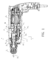
- Fig. 1 shows a hammer drill in accordance with an embodiment of the invention comprising a shell 10 and a motor 20 disposed in the shell 10.
- the motor 20 comprises an output rotary shaft 21 with a first pinion 22 thereon.
- An intermediate rotary shaft 30 is disposed parallel to the output rotary shaft 20 and comprises a second pinion 32 engaged with the first pinion 22 to transmit rotary power from the output rotary shaft 20 to the intermediate rotary shaft 30 and to a third pinion 31.
- a swing link comprises a bearing 40 having a sleeve 43 engaged with teeth 33 on the intermediate rotary shaft 30 and a connecting bar 41 connected to a piston 60.
- a first spring 42 is interposed between the bearing 40 and the intermediate rotary shaft 30 to urge the sleeve 43 and the teeth 33 into engagement so that the teeth 33 and the sleeve 43 perform a clutch function.
- a cylinder 50 covers the piston 60 and comprises a gear 51 engaged with the third pinion 31.
- the gear 51 can move along the axis of the cylinder 50.
- a second spring 52 is disposed on one side of the gear 51 to bring the gear 51 and the third pinion 31 into engagement so as to transmit rotary power from the intermediate rotary shaft 30 to the cylinder 50.
- the cylinder 50 is driven linearly by the piston 60.
- a collet 70 is mounted on one end of the cylinder 50 and an aiguille 80 is gripped in the collet 70.
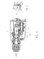
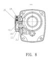
- the hammer drill further comprises a control mechanism 100 which is shown in outline in Figures 2, 4 and 6, in cross-section in Figures 3, 5 and 7 and in situ in Figure 8.
- the control mechanism 100 itself comprises a rotary control button 110, a guide device 120 and a slide device 130.
- the rotary control button 110 has an eccentric shaft 111 parallel to its rotary axis.
- the slide device 130 defines a slide channel 131 which receives the eccentric shaft 111 and an access hole 132 through which the guide device 120 passes.
- the eccentric shaft 111 translates rotary motion of the rotary control button 110 into a linear displacement of the slide device 130 along the guide device 120.
- the slide device 130 also comprises a first pushing bar 133 and a second pushing bar 134.
- the eccentric shaft 111 rotates eccentrically and is displaced in a relative horizontal direction.
- the first pushing bar 133 and the second pushing bar 134 move to push the gear 51 and sleeve 43 respectively and this serves to disengage the gear 51 from the third pinion 31 and the teeth 33 from the sleeve 43.
- the control button 110 is rotated to move the slide device 130 to the left.
- the first pushing bar 133 moves to push the gear 51 which disengages the third pinion 31.
- the cylinder 50 loses rotary power and the aiguille 80 cannot drill.
- the sleeve 43 and the teeth 33 remain engaged so the aiguille 80 can hammer ( ie the hammer mode).
- the control button 110 is rotated to move the slide device 130 to the right.
- the second pushing bar 134 moves to push the sleeve 43 which disengages the teeth 33.
- the swing link 40 loses power and the aiguille 80 can not hammer.
- the gear 51 and the third pinion 31 remain engaged so the aiguille 80 can drill.
- the rotary control button 110 pivotally engages the shell 10 via an axial bolt 112.
- the shell 10 comprises three locking devices 11 to engage a fastening device 113 in three different positions respectively.
- a third spring 114 is disposed between the fastening device 113 and the rotary control button 110.
- Each of the locking devices 11 defines a groove for receiving the fastening device 113.
Landscapes
- Engineering & Computer Science (AREA)
- Mechanical Engineering (AREA)
- Percussive Tools And Related Accessories (AREA)
- Drilling And Boring (AREA)
- Earth Drilling (AREA)
Applications Claiming Priority (2)
| Application Number | Priority Date | Filing Date | Title |
|---|---|---|---|
| CNU2003201202169U CN2661382Y (zh) | 2003-12-02 | 2003-12-02 | 锤钻 |
| CH320120216 | 2003-12-02 |
Publications (1)
| Publication Number | Publication Date |
|---|---|
| EP1537955A2 true EP1537955A2 (de) | 2005-06-08 |
Family
ID=34347932
Family Applications (1)
| Application Number | Title | Priority Date | Filing Date |
|---|---|---|---|
| EP20040257265 Withdrawn EP1537955A2 (de) | 2003-12-02 | 2004-11-23 | Bohrhammer |
Country Status (2)
| Country | Link |
|---|---|
| EP (1) | EP1537955A2 (de) |
| CN (1) | CN2661382Y (de) |
Cited By (8)
| Publication number | Priority date | Publication date | Assignee | Title |
|---|---|---|---|---|
| WO2008000545A1 (de) * | 2006-06-27 | 2008-01-03 | Robert Bosch Gmbh | Elektrohandwerkzeug |
| JP2009279738A (ja) * | 2008-05-26 | 2009-12-03 | Max Co Ltd | 駆動工具 |
| CN105515287A (zh) * | 2016-02-01 | 2016-04-20 | 浙江绿动电机科技有限公司 | 水钻工具 |
| JP2016129911A (ja) * | 2015-01-13 | 2016-07-21 | 株式会社マキタ | 電動工具 |
| WO2017073236A1 (ja) * | 2015-10-30 | 2017-05-04 | 日立工機株式会社 | ハンマドリル |
| US10046450B2 (en) | 2014-07-28 | 2018-08-14 | Black & Decker Inc. | Mode change knob assembly |
| CN110153960A (zh) * | 2018-02-14 | 2019-08-23 | 苏州宝时得电动工具有限公司 | 冲击工具 |
| WO2021036095A1 (zh) * | 2019-08-28 | 2021-03-04 | 浙江信源电器制造有限公司 | 一种新型电锤 |
Families Citing this family (6)
| Publication number | Priority date | Publication date | Assignee | Title |
|---|---|---|---|---|
| CN100420531C (zh) * | 2005-05-26 | 2008-09-24 | 松下电工株式会社 | 锤钻 |
| CN2920563Y (zh) * | 2006-07-11 | 2007-07-11 | 王文江 | 轻型单钮四功能电锤 |
| DE102008040031A1 (de) * | 2008-06-30 | 2009-12-31 | Robert Bosch Gmbh | Mehrgang-Getriebevorrichtung und Werkzeugmaschine |
| DE102008054692A1 (de) | 2008-12-16 | 2010-06-17 | Robert Bosch Gmbh | Handwerkzeugmaschine |
| CN105569558A (zh) * | 2016-03-07 | 2016-05-11 | 湖州中辰建设有限公司 | 一种带有气动活塞装置的冲击钻 |
| CN214723942U (zh) * | 2019-12-09 | 2021-11-16 | 苏州宝时得电动工具有限公司 | 电锤 |
-
2003
- 2003-12-02 CN CNU2003201202169U patent/CN2661382Y/zh not_active Expired - Lifetime
-
2004
- 2004-11-23 EP EP20040257265 patent/EP1537955A2/de not_active Withdrawn
Cited By (8)
| Publication number | Priority date | Publication date | Assignee | Title |
|---|---|---|---|---|
| WO2008000545A1 (de) * | 2006-06-27 | 2008-01-03 | Robert Bosch Gmbh | Elektrohandwerkzeug |
| JP2009279738A (ja) * | 2008-05-26 | 2009-12-03 | Max Co Ltd | 駆動工具 |
| US10046450B2 (en) | 2014-07-28 | 2018-08-14 | Black & Decker Inc. | Mode change knob assembly |
| JP2016129911A (ja) * | 2015-01-13 | 2016-07-21 | 株式会社マキタ | 電動工具 |
| WO2017073236A1 (ja) * | 2015-10-30 | 2017-05-04 | 日立工機株式会社 | ハンマドリル |
| CN105515287A (zh) * | 2016-02-01 | 2016-04-20 | 浙江绿动电机科技有限公司 | 水钻工具 |
| CN110153960A (zh) * | 2018-02-14 | 2019-08-23 | 苏州宝时得电动工具有限公司 | 冲击工具 |
| WO2021036095A1 (zh) * | 2019-08-28 | 2021-03-04 | 浙江信源电器制造有限公司 | 一种新型电锤 |
Also Published As
| Publication number | Publication date |
|---|---|
| CN2661382Y (zh) | 2004-12-08 |
Similar Documents
| Publication | Publication Date | Title |
|---|---|---|
| US7331496B2 (en) | Hammer drill | |
| US7748472B2 (en) | Hammer drill | |
| JP3582760B2 (ja) | ハンマドリル | |
| CN101664917B (zh) | 锤钻 | |
| US20090145617A1 (en) | Portable power drill with gearbox | |
| EP2809470B1 (de) | Bohrhammer | |
| RU2258125C2 (ru) | Бурильный молоток с механизмом для предотвращения самопроизвольных ударов молотка | |
| US7174969B2 (en) | Rotary hammer | |
| CN100556594C (zh) | 手操作式工具机 | |
| US6913090B2 (en) | Hammer | |
| EP1702723B1 (de) | Überlastkupplungsvorrichtung für Kraftwerkzeug | |
| US20090308626A1 (en) | Electric hand tool | |
| CN101633163A (zh) | 具有传动转换器的电动工具 | |
| CN101541480A (zh) | 手持式工具机 | |
| JP4446248B2 (ja) | ハンマドリル | |
| GB2418634A (en) | Power tool comprising a drive that can be switched over between drilling, percussion drilling and chiselling operating modes | |
| JP5055749B2 (ja) | ハンマドリル | |
| EP3034243B1 (de) | Bohrhammer | |
| CN2661382Y (zh) | 锤钻 | |
| GB2102718A (en) | Improvements in or relating to rotary percussive drills | |
| CN201253841Y (zh) | 锤钻 | |
| JPH09239675A (ja) | ハンマドリルの動作モード切換装置 | |
| CN107344349B (zh) | 电动工具 | |
| RU2200816C2 (ru) | Ударно-вращательная машина | |
| CN113231993B (zh) | 一种旋钮组件及电锤 |
Legal Events
| Date | Code | Title | Description |
|---|---|---|---|
| PUAI | Public reference made under article 153(3) epc to a published international application that has entered the european phase |
Free format text: ORIGINAL CODE: 0009012 |
|
| AK | Designated contracting states |
Kind code of ref document: A2 Designated state(s): AT BE BG CH CY CZ DE DK EE ES FI FR GB GR HU IE IS IT LI LU MC NL PL PT RO SE SI SK TR |
|
| AX | Request for extension of the european patent |
Extension state: AL HR LT LV MK YU |
|
| STAA | Information on the status of an ep patent application or granted ep patent |
Free format text: STATUS: THE APPLICATION HAS BEEN WITHDRAWN |
|
| 18W | Application withdrawn |
Effective date: 20071203 |