EP1537608B1 - Verfahren zum elektronischen betrieb einer steuereinrichtung für ein piezobetätigungsglied - Google Patents
Verfahren zum elektronischen betrieb einer steuereinrichtung für ein piezobetätigungsglied Download PDFInfo
- Publication number
- EP1537608B1 EP1537608B1 EP03760731A EP03760731A EP1537608B1 EP 1537608 B1 EP1537608 B1 EP 1537608B1 EP 03760731 A EP03760731 A EP 03760731A EP 03760731 A EP03760731 A EP 03760731A EP 1537608 B1 EP1537608 B1 EP 1537608B1
- Authority
- EP
- European Patent Office
- Prior art keywords
- branch
- diodes
- transistors
- current
- voltage
- Prior art date
- Legal status (The legal status is an assumption and is not a legal conclusion. Google has not performed a legal analysis and makes no representation as to the accuracy of the status listed.)
- Expired - Lifetime
Links
- 238000000034 method Methods 0.000 title claims description 14
- 238000004804 winding Methods 0.000 claims description 33
- 230000000737 periodic effect Effects 0.000 claims description 13
- 230000009466 transformation Effects 0.000 claims description 13
- 230000005284 excitation Effects 0.000 claims description 9
- 238000012163 sequencing technique Methods 0.000 claims description 8
- 239000000446 fuel Substances 0.000 description 7
- 238000002347 injection Methods 0.000 description 7
- 239000007924 injection Substances 0.000 description 7
- 241001080024 Telles Species 0.000 description 6
- 239000000919 ceramic Substances 0.000 description 5
- 238000010586 diagram Methods 0.000 description 5
- 230000000694 effects Effects 0.000 description 5
- 230000002123 temporal effect Effects 0.000 description 3
- 238000002485 combustion reaction Methods 0.000 description 1
- 238000005516 engineering process Methods 0.000 description 1
- 239000004065 semiconductor Substances 0.000 description 1
- 239000007921 spray Substances 0.000 description 1
- 238000009834 vaporization Methods 0.000 description 1
- 230000008016 vaporization Effects 0.000 description 1
Images


Classifications
-
- F—MECHANICAL ENGINEERING; LIGHTING; HEATING; WEAPONS; BLASTING
- F02—COMBUSTION ENGINES; HOT-GAS OR COMBUSTION-PRODUCT ENGINE PLANTS
- F02M—SUPPLYING COMBUSTION ENGINES IN GENERAL WITH COMBUSTIBLE MIXTURES OR CONSTITUENTS THEREOF
- F02M51/00—Fuel-injection apparatus characterised by being operated electrically
- F02M51/06—Injectors peculiar thereto with means directly operating the valve needle
- F02M51/0603—Injectors peculiar thereto with means directly operating the valve needle using piezoelectric or magnetostrictive operating means
-
- F—MECHANICAL ENGINEERING; LIGHTING; HEATING; WEAPONS; BLASTING
- F02—COMBUSTION ENGINES; HOT-GAS OR COMBUSTION-PRODUCT ENGINE PLANTS
- F02D—CONTROLLING COMBUSTION ENGINES
- F02D41/00—Electrical control of supply of combustible mixture or its constituents
- F02D41/20—Output circuits, e.g. for controlling currents in command coils
- F02D41/2096—Output circuits, e.g. for controlling currents in command coils for controlling piezoelectric injectors
-
- H—ELECTRICITY
- H02—GENERATION; CONVERSION OR DISTRIBUTION OF ELECTRIC POWER
- H02N—ELECTRIC MACHINES NOT OTHERWISE PROVIDED FOR
- H02N2/00—Electric machines in general using piezoelectric effect, electrostriction or magnetostriction
- H02N2/02—Electric machines in general using piezoelectric effect, electrostriction or magnetostriction producing linear motion, e.g. actuators; Linear positioners ; Linear motors
- H02N2/06—Drive circuits; Control arrangements or methods
- H02N2/065—Large signal circuits, e.g. final stages
- H02N2/067—Large signal circuits, e.g. final stages generating drive pulses
-
- F—MECHANICAL ENGINEERING; LIGHTING; HEATING; WEAPONS; BLASTING
- F02—COMBUSTION ENGINES; HOT-GAS OR COMBUSTION-PRODUCT ENGINE PLANTS
- F02M—SUPPLYING COMBUSTION ENGINES IN GENERAL WITH COMBUSTIBLE MIXTURES OR CONSTITUENTS THEREOF
- F02M2200/00—Details of fuel-injection apparatus, not otherwise provided for
- F02M2200/21—Fuel-injection apparatus with piezoelectric or magnetostrictive elements
Definitions
- the present invention relates to a method for electronically controlling the control device of an ultrasonic piezoelectric actuator, and more particularly to a fuel injector with a piezoelectric stage controlled by the electronic injection computer of a combustion engine. internal in a motor vehicle.
- an ultrasonic piezoelectric stage fuel injector is used to spray the fuel very finely, with droplets calibrated to ensure accurate dosing and small enough to ensure complete and homogeneous vaporization of the injected fuel.
- an injector comprises, inter alia, a cylindrical nozzle supplied with fuel and at the end of which is provided an injection orifice, and means for cyclically vibrating the nozzle, such as a transducer, comprising a ceramic stage.
- a piezoelectric injector ceramic is equivalent, in the first order, to a capacity whose charging voltage is high, greater than a hundred volts.
- This transducer is controlled in duration and intensity by an electronic control device, itself controlled by the engine control electronic system to achieve an oscillating opening with ultrasonic frequency of the nose of the nozzle.
- the electronic control device is intended to generate a high voltage alternating signal, greater than one hundred volts, of high frequency, greater than about ten kiloHertz, for exciting the piezoelectric cells from a DC voltage source.
- the battery provides a supply voltage of 12 or 42 volts, which involves increasing this voltage by a DC-DC voltage booster converter powered by the low voltage of the battery.
- This bridge connection is made from two arms mounted in parallel across the voltage source B and each consisting of two bridge switches P 1 and P 2 in series alternately controllable respectively P 3 and P 4 , whose points media J 1 , respectively J 2 , are connected to the two terminals of the primary winding L 1 .
- the diagram shows four piezoelectric ceramics I 1 , .. ,, I i , ..., I 4 which are connected in parallel and, in a first mode embodiment, selected successively by a controllable selection switch K i series-connected with each of them.
- the four injectors I i are connected on the one hand to the inductor L of resonance intended to constitute an oscillating circuit with each injector successively, and secondly two by two by a relay R 1 and R 2 respectively, each connected to a terminal of a selection switch K 1 and K 2 respectively, the other terminal is connected to ground.
- the injection computer first drives the relays and then simultaneously the selection and bridge switches to select the injector to be controlled which must be open during the intervals of activity to ensure the supply of fuel to the corresponding cylinder of the engine. .
- this control circuit is as follows, depending on the control of the different switches.
- the control signal sent by the injection computer controls, on the one hand, the closing of the selection switch K i connected to the chosen injector I i and, on the other hand, the simultaneous closing of the switches of bridge P 1 and P 4 , thus connecting the terminal J 1 of the primary winding L 1 to the terminal (+) of the battery B and its terminal J 2 to the (-) terminal of the battery.
- the signal controls the opening of the switches P 1 and P 4 and the simultaneous closing of the two switches P 2 and P 3 , thus connecting the terminal J 1 of the primary winding L 1 to the (-) terminal of the battery B and its terminal J 2 to the (+) terminal and the voltage v 1 to its negative terminals is equal to -E.
- the voltage V s across the secondary winding L 2 becomes negative and equal to -mE.
- the voltage V ci across the injector I i is then a sinusoidal signal of the same period as the voltage V s across the secondary winding L 2 , as shown in FIG. 2b, oscillating between a maximum value + V m and a minimum value -V m .
- the injection computer then successively controls the other injectors I i connected in parallel.
- the computer controls the quiescence of the relay R 1 to the injector I 1 while the relay R 2 is in the rest position, as well as the closing the switch K 1 and opening the switch K 2 , in order to connect the actuator I 1 to the inductor L resonance.
- the relay R 2 is switched to the working position while the relay R 2 is still switched to the working position to the injector I 3 , and simultaneously the switch K 2 is closed to the time t 4 while the switch K 1 is open from time t 1 , so that the voltage V s across the secondary winding L 3 causes the resonance of the oscillating circuit constituted by the inductance L and the injector I 3 to which it is then connected.
- the voltage signal V c3 across the injector I 3 is a sinusoid of maximum amplitude mGE between the following instants t 3 and t 4 .
- the switch K 1 is closed again and the switch K 2 is open, but the relay R 1 is switched to the injector I 2 so its control is the opposite of that existing between times t 0 and t 1 .
- the voltage signal V c2 across the injector I 2 is a sinusoid of maximum amplitude mGE between the following instants t 5 and t 6 .
- the voltage V c across the load consisting of the transformer, the resonance inductor and the actuator being a square signal with a switching frequency f r determined
- the current I c circulating in the load is a periodic signal of resonant frequency f o such that the switching frequency f r is at least twice as small as it, f r ⁇ 2f o , so that at the closing of the switches the current is zero in the circuit.
- This control mode of the hypo-discontinuous type of control switches is obtained from the values of the transformer transformation ratio and the resonance inductance determined as a function of the value of the equivalent capacity of the actuator. It makes it possible to limit the switching losses of the switches when they are closed and to limit the effects of electromagnetic compatibility by power failure.
- the control computer controls, on the one hand, the closing of the selection means connected to said actuator and, on the other hand, simultaneously, in a first phase, the closing of a first pair of voltage switches. bridge consisting of a first switch T 1 of the first arm and a second switch T 4 of a second arm and the opening of the second pair formed by the other two switches T 2 and T 3 of said arms, and in a second phase switching said four switches to an inverse position so as to obtain a periodic voltage across the transformer secondary winding, these two phases being repeated a specified number of times during the operating time of the actuator to generate a high signal voltage and high frequency on the piezoelectric actuator from the DC voltage source.
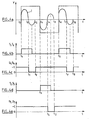
- the control sequencing of the four switches of the control device is as follows, during two consecutive phases, the first of which takes place between the instants t 0 and t 3 and the second takes place between the instants t 3 and t 6 .
- the transistors T 1 and T 4 are closed when the current Ic is zero in the diodes D 1 and D 4 .
- these transistors T 1 and T 4 are closed allowing the current I c to pass , while the diodes D 1 and D 4 are not conducting, the voltage at their terminals being equal to + E.
- the transistors T 2 and T 3 are closed when the current I c is zero in the diodes D 2 and D 3 . Between times t 3 and t 4 , these transistors T 2 and T 3 are closed allowing the current I c to pass , while the diodes D 2 and D 3 do not conduct.
- FIGS. 4b and 4d show the time variations of the control voltages across the bridge transistors
- FIGS. 4c and 4e represent the voltages across the diodes, connected in parallel with these bridge transistors, either their on state or non-conducting state. .
- the DC / AC voltage booster / converter is sized so that the switching frequency f r desired for driving the piezoelectric injector meets the conditions previously stated with respect to the resonant frequency f o .
- FIG. 5a represents the waveform generated by the bridge of the control device, in continuous hypo mode according to the invention.
- the transistors T 1 and T 4 are closed when the current I c is zero in the diodes D 1 and D 4 and the other diodes D 2 and D 3 are conducting. Between times t 0 and t 1 , these transistors T 1 and T 4 are closed allowing the current I c to pass , while the four diodes D 1 to D 4 are not conducting. At time t 1 , the current I c reverses, the two diodes D 1 and D 4 become conducting and the two transistors T 1 and T 4 are controlled at the opening between this instant t1 and the instant t 2 where there is no current in these two transistors.
- the transistors T 2 and T 3 are closed when the diodes D 1 and D 4 are still on. At this time of closure, the diodes D 1 and D 4 are naturally locked and the current I c flows in the same direction. Between instants t 3 and t 4 , the current I c reverses and the diodes D 2 and D 3 become conductive and these transistors T 2 and T 3 are controlled to be open when there is no current Ic in these transistors. At the moment t 4 , the two transistors T 1 and T 4 are controlled on closing, the two diodes D 2 and D 3 become non-conducting and the driving starts again according to the same sequencing as between times t 0 and t 4 .
- FIGS. 5b and 5d represent the time variations, in hypo-continuous mode, of the control voltages at the terminals of the bridge transistors
- FIGS. 5c and 5e represent the voltages at the terminals of the diodes, connected in parallel with these bridge transistors, either their passing state or non-conducting state.
- the voltage V c across the load formed by the transformer, the resonance inductor and the actuator being a square signal of a given switching frequency
- the current Ic flowing in the load is a periodic signal, in phase lag with the voltage V c , and with a resonant frequency f o such that the switching frequency f r is greater than half the resonance frequency f o , f r > f 0 / 2, so that it controls the closing of the zero-voltage switches at the terminals of the control switch.
- This control mode of the hyper-continuous type of control switches is obtained from the values of the transformer transformation ratio and the resonance inductance determined as a function of the value of the equivalent capacity of the actuator. This mode of controlling the hyper-continuous control switches makes it possible to limit the switching losses of the switches when they are opened and to limit the effects of electromagnetic compatibility by voltage switching.
- This control mode is of the ZVC control type when closing the switches or "zero voltage switching".
- the DC / AC voltage booster / converter is sized so that the switching frequency f r desired for driving the piezoelectric injector meets the conditions previously stated with respect to the resonant frequency f o .
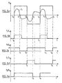
- FIG. 6a represents the waveform generated by the bridge of the control device, in supercontinuous mode according to the invention.
- the control sequencing of the four switches of the control device is as follows during two consecutive phases, the first of which takes place between the instants t 0 and t 2 and the second takes place between the instants t 2 and t 4 .
- the transistors T 1 and T 4 are controlled on closing, while the two diodes D 1 and D 2 are conducting, so that there is no voltage across these terminals. transistors.
- the other diodes D 2 and D 3 are not on and the two transistors T 2 and T 3 are open.
- the diodes D 1 and D 4 are blocked.
- the two transistors T 1 and T 4 are still closed, allowing current I c to pass .
- the transistors T 1 and T 4 are controlled at the opening, the diodes D 2 and D 3 become conducting and there is no voltage across the transistors T 2 and T 3 .
- the diodes D 1 and D 4 are not busy.
- transistors T 2 and T 3 are controlled on closing and are then commanded to open at time t 4 .
- FIGS. 6c and 6e show the time variations, in super-continuous mode, of the control voltages at the terminals of the bridge transistors
- FIGS. 6b and 6d represent the voltages at the terminals of the diodes, connected in parallel with these bridge transistors, either their passing state or non-conducting state.
- the control method combines the three control modes of the switches, of hypo-discontinuous, hypo-continuous and hyper-continuous types, as a function of the voltage E of the battery which can vary and the peak voltage of the control signal of the piezoelectric actuators.
- the switches for selecting the actuators and the primary windings of the transformers can be bidirectionally current-controlled, and for this purpose they can be made from two semiconductors connected in series or in parallel. This can be for example two MOSFET transistors connected in series or IGBT with anti-parallel diode.
- the relays R for selecting the actuators are electromechanical type, monostable and having a rest contact and a working contact.
- selector switches of the transformers they are preferably of the P-channel MOSFET type, for their low voltage drops.
Landscapes
- Engineering & Computer Science (AREA)
- Chemical & Material Sciences (AREA)
- Combustion & Propulsion (AREA)
- Mechanical Engineering (AREA)
- General Engineering & Computer Science (AREA)
- Fuel-Injection Apparatus (AREA)
- General Electrical Machinery Utilizing Piezoelectricity, Electrostriction Or Magnetostriction (AREA)
- Electrical Control Of Air Or Fuel Supplied To Internal-Combustion Engine (AREA)
Claims (7)
- Verfahren zur elektronischen Steuerung einer Steuervorrichtung mindestens eines piezoelektrischen Ultraschallaktors ausgehend von einem Kontrollrechner, der einen Gleichspannungs-/Wechselspannungs-Wandler/Erhöher aufweist, der von einer Gleichspannungsquelle (B) gespeist wird, deren Hochspannungsausgang mit einem Schwingkreis verbunden ist, der aus dem Aktor (Ii) und einer Resonanzinduktivität (L) gebildet wird, wobei der Wandler aus einer Schaltung mit mindestens einem Transformator mit mindestens einer Primärwicklung, die mit der Spannungsquelle über mindestens einen steuerbaren Unterbrecher verbunden ist, und einer einzigen Sekundärwicklung gebildet wird, die ein Wechselstromsignal zur Anregung des piezoelektrischen Aktors liefert, und derart, dass die Spannung (Vc) an den Klemmen der Last, die aus dem Transformator, der Resonanzinduktivität und dem Aktor besteht, ein Rechtecksignal mit einer bestimmten Pendelfrequenz (fr) ist, dadurch gekennzeichnet, dass der in der Last fließende Strom (Ic) ein periodisches Signal mit einer derartigen Resonanzfrequenz (f0) ist, dass die Pendelfrequenz (fr) niedriger als das Doppelte der Resonanzfrequenz ist (fr<2f0), so dass er das Schließen der Unterbrecher bei Nullstrom in der Schaltung steuert, wobei dieser Steuerungsmodus der Unterbrecher vom Typ hypo-diskontinuierlich ausgehend vom Transformationsverhältnis des Transformators und der Resonanzinduktivität erhalten wird, die in Abhängigkeit von der äquivalenten Kapazität des Aktors bestimmt werden.
- Verfahren zur elektronischen Steuerung der Steuervorrichtung mindestens eines piezoelektrischen Ultraschallaktors nach Anspruch 1, dadurch gekennzeichnet, dass der in der Last fließende Strom (Ic) ein periodisches Signal mit Phasenvoreilung bezüglich der Spannung (Vc) und mit einer derartigen Resonanzfrequenz (f0) ist, dass die Pendelfrequenz (fr) zwischen der Hälfte der Resonanzfrequenz und ihrem Doppelten liegt (f0/2<fr<2f0), so dass er das Schließen der Unterbrecher bei Nullstrom im Steuerschalter steuert, wobei dieser Steuermodus der Unterbrecher vom Typ hypo-kontinuierlich ausgehend vom Transformationsverhältnis des Transformators und der Resonanzinduktivität erhalten wird, die in Abhängigkeit von der äquivalenten Kapazität des Aktors bestimmt werden.
- Verfahren zur elektronischen Steuerung einer Steuervorrichtung mindestens eines piezoelektrischen Ultraschallaktors ausgehend von einem Kontrollrechner, der einen Gleichspannungs-/Wechselspannungs-Wandler/Erhöher aufweist, der von einer Gleichspannungsquelle gespeist wird, deren Hochspannungsausgang mit einem Schwingkreis verbunden ist, die aus dem Aktor und einer Resonanzinduktivität gebildet wird, wobei der Wandler aus einer Schaltung mit mindestens einem Transformator mit mindestens einer Primärwicklung, die mit der Spannungsquelle über mindestens einen steuerbaren Unterbrecher verbunden ist, und einer einzigen Sekundärwicklung gebildet wird, die ein Wechselstromsignal zur Anregung des piezoelektrischen Aktors liefert, und derart, dass die Spannung (Vc) an den Klemmen der Last, die aus dem Transformator, der Resonanzinduktivität und dem Aktor besteht, ein Rechtecksignal mit bestimmter Pendelfrequenz (fr) ist, dadurch gekennzeichnet, dass der in der Last fließende Strom (Ic) ein periodisches Signal ist, mit Phasenverzögerung bezüglich der Spannung (Vc) und mit einer derartigen Resonanzfrequenz (f0), dass die Pendelfrequenz (fr) höher ist als die Hälfte der Resonanzfrequenz (fr>f0/2), so dass er das Schließen der Unterbrecher bei Nullspannung an den Klemmen des Steuerschalters steuert, wobei dieser Steuermodus der Unterbrecher vom hyperkontinuierlichen Typ ausgehend vom Transformationsverhältnis des Transformators und der Resonanzinduktivität erhalten wird, die in Abhängigkeit von der äquivalenten Kapazität des Aktors bestimmt werden.
- Verfahren zur elektronischen Steuerung der Steuervorrichtung mindestens eines piezoelektrischen Ultraschallaktors, mit einem Wandler, der aus einem Brückenbetrieb mit mindestens einem Transformator besteht, der mindestens eine Primärwicklung hat, die ausgehend von einem ersten Arm, der aus zwei Brückenunterbrechern (T1, T2) in Reihe besteht, die alternativ steuerbar sind, und aus mindestens einem zweiten Arm parallel zum ersten Arm hergestellt wird, der auch aus zwei Brückenunterbrechern (T2, T3) in Reihe besteht, die alternativ steuerbar sind, wobei der Mittenpunkt des zweiten Arms mit dem Mittenpunkt des ersten Arms durch eine Last verbunden ist, die aus dem Transformator, einer Resonanzinduktivität (L) und dem piezoelektrischen Aktor besteht, nach Anspruch 1, dadurch gekennzeichnet, dass die Steuerungsreihenfolge der vier Unterbrecher des Wandlers folgendermaßen ist:während einer ersten Phase:- werden im Zeitpunkt t0 ein erster Transistor (T1) des ersten Arms und ein zweiter Unterbrecher (T2) des zweiten Arms, die ein erstes Paar bilden, in Schließrichtung gesteuert, wenn der Strom (Ic) in den antiparallel geschalteten Dioden (D1 und D4) Null ist;- sind zwischen den Zeitpunkten t0 und t1 die Transistoren (T1 und T4) des ersten Paars geschlossen und lassen einen Strom (Ic) durch, während die Dioden (D1 und D4) nicht leitend sind und der zweite Transistor (T2) des ersten Arms und der erste Transistor des zweiten Arms (T3), die ein zweites Paar bilden, offen sind;- kehrt der Strom (Ic) im Zeitpunkt t1 um, die zwei Dioden (D1 und D4) werden leitend und die zwei Transistoren (T1 und T4) des ersten Paars werden zwischen diesem Zeitpunkt t1 und dem Zeitpunkt t2, in dem die Dioden (D1 und D4) nicht mehr leiten, in Öffnungsrichtung gesteuert, wobei der Strom zu Null wird;während einer zweiten Phase:wobei diese beiden Phasen eine vorbestimmten Anzahl von Zyklen während der Betriebsdauer des Aktors wiederholt werden, um ein Hochspannungssignal im piezoelektrischen Aktor ausgehend von der Gleichspannungsquelle zu erzeugen.- werden im Zeitpunkt t3 die Transistoren (T2 und T3) des zweiten Paars in Schließrichtung gesteuert, wenn der Strom (Ic) in den antiparallel geschalteten Dioden (D2 und D3) Null ist;- sind zwischen den Zeitpunkten t3 und t4 diese Transistoren (T2 und T3) leitend und lassen den Strom (Ic) durch, während die Dioden (D2 und D3) nicht leiten und die Transistoren (T1 und T4) des ersten Paars offen sind;- kehrt der Strom (Ic) im Zeitpunkt t4 um, die zwei Dioden (D2 und D3) werden leitend, und die zwei Transistoren (T2 und T3) werden zwischen diesem Zeitpunkt t4 und dem Zeitpunkt t5, in dem die Dioden nicht mehr leiten, in Öffnungsrichtung gesteuert, wobei der Strom erneut zu Null wird,
- Verfahren zur elektronischen Steuerung der Steuervorrichtung mindestens eines piezoelektrischen Ultraschallaktors, mit einem Wandler, der aus einer Brückenschaltung mit mindestens einem Transformator besteht, der mindestens eine Primärwicklung hat, die ausgehend von einem ersten Arm, der aus zwei Brückenunterbrechern (T1, T2) in Reihe besteht, die alternativ steuerbar sind, und aus mindestens einem zweiten Arm parallel zum ersten Arm gebildet wird, der auch aus zwei Brückenunterbrechern (T2, T3) in Reihe besteht, die alternativ steuerbar sind, wobei der Mittenpunkt des zweiten Arms mit dem Mittenpunkt des ersten Arms über eine Last verbunden ist, die aus dem Transformator, einer Resonanzinduktivität (L) und dem piezoelektrischen Aktor besteht, nach Anspruch 2, dadurch gekennzeichnet, dass die Steuerungsreihenfolge der vier Unterbrecher des Wandlers folgendermaßen ist:während einer ersten Phase:- werden im Zeitpunkt t0 ein erster Transistor (T1) des ersten Arms und ein zweiter Unterbrecher (T4) des zweiten Arms, die ein erstes Paar bilden, in Schließrichtung gesteuert, wenn der Strom (Ic) in den antiparallel geschalteten Dioden (D1 und D4) Null ist und die anderen antiparallel geschalteten Dioden (D2 und D3) des zweiten Transistors (T2) des ersten Arms und des ersten Transistors (T3) des zweiten Arms leitend sind;- sind zwischen den Zeitpunkten t0 und t1 die Transistoren (T1 und T4) des ersten Paars geschlossen und lassen den Strom (Ic) durch, während die vier Dioden (D1 bis D4) nicht leitend sind;- kehrt der Strom (Ic) im Zeitpunkt t1 um, die zwei Dioden (D1 und D4) werden leitend, und die zwei Transistoren (T1 und T4) werden zwischen diesem Zeitpunkt t1 und dem Zeitpunkt t2, in dem es keinen Strom in diesen zwei Transistoren gibt, in Öffnungsrichtung gesteuert;- werden in diesem gleichen Zeitpunkt t2 die Transistoren (T2 und T3) des zweiten Paars in Schließrichtung gesteuert, während die Dioden (D1 und D4) noch leitend sind; in diesem Schließzeitpunkt blockieren die Dioden (D1 und D4) sich natürlich und der Strom (Ic) fließt in der gleichen Richtung;- kehrt der Strom (Ic) zwischen den Zeitpunkten t3 und t4 um, und die Dioden (D2 und D3) werden leitend, und diese Transistoren (T2 und T3) werden gesteuert, um offen zu sein, während es keinen Strom (Ic) mehr in diesen Transistoren gibt;- werden im Zeitpunkt t4 die zwei Transistoren (T1 und T4) in Schließrichtung gesteuert, die zwei Dioden (D2 und D3) werden nicht leitend, und die Steuerung beginnt erneut gemäß der gleichen Steuerungsreihenfolge wie zwischen den Zeitpunkten t0 und t1.
- Verfahren zur elektronischen Steuerung der Steuervorrichtung mindestens eines piezoelektrischen Ultraschallaktors, mit einem mit einem Wandler, der aus einer Brückenschaltung mit mindestens einem Transformator besteht, der mindestens eine Primärwicklung hat, die ausgehend von einem ersten Arm, der aus zwei Brückenunterbrechern (T1, T2) in Reihe besteht, die alternativ steuerbar sind, und aus mindestens einem zweiten Arm parallel zum ersten Arm gebildet wird, der auch aus zwei Brückenunterbrechern (T2, T3) in Reihe besteht, die alternativ steuerbar sind, wobei der Mittenpunkt des zweiten Arms mit dem Mittenpunkt des ersten Arms über eine Last verbunden ist, die aus dem Transformator, einer Resonanzinduktivität (L) und dem piezoelektrischen Aktor besteht, nach Anspruch 3, dadurch gekennzeichnet, dass die Steuerungsreihenfolge der vier Unterbrecher des Wandlers folgendermaßen ist:während einer ersten Phase:- werden zwischen den Zeitpunkten t0 und t1 ein erster Transistor (T1) des ersten Arms und ein zweiter Unterbrecher (T4) des zweiten Arms, die ein erstes Paar bilden, in Schließrichtung gesteuert, während die zwei antiparallel geschalteten Dioden (D1 und D2) und die anderen antiparallel geschalteten Dioden (D2 und D3) des zweiten Transistors (T2) des ersten Arms und des ersten Transistors (T3) des zweiten Arms nicht leitend sind und die zwei Transistoren (T2 und T3) offen sind;- sind im Zeitpunkt t1 die Dioden (D1 und D4) des ersten Paars von Transistoren blockiert;- sind zwischen den Zeitpunkten t1 und t2 die zwei Transistoren (T1 und T4) des ersten Paars noch geschlossen und lassen den Strom (Ic) durch;- werden im Zeitpunkt t2 die Transistoren (T1 und T4) des ersten Paars in Öffnungsrichtung gesteuert, werden die antiparallel geschalteten Dioden (D2 und D3) des zweiten Paars von Transistoren leitend und gibt es keine Spannung mehr an den Klemmen der Transistoren (T2 und T3), die Dioden (D1 und D4) sind nicht leitend;- werden zwischen den Zeitpunkten t2 und t3 die Transistoren (T2 und T3) des zweiten Paars in Schließrichtung gesteuert, um anschließend im Zeitpunkt t4 in Öffnungsrichtung gesteuert zu werden.
- Verfahren zur elektronischen Steuerung einer Steuervorrichtung mindestens eines piezoelektrischen Ultraschallaktors nach einem der Ansprüche 1 bis 6, dadurch gekennzeichnet, dass es die drei Steuermodi der Unterbrecher vom Typ hypo-diskontinuierlich, hypo-kontinuierlich und hyperkontinuierlich zeitlich in Abhängigkeit von der Spannung (E) der Batterie, die variieren kann, und der Spitzenspannung des Steuersignals der piezoelektrischen Aktoren kombiniert.
Applications Claiming Priority (3)
| Application Number | Priority Date | Filing Date | Title |
|---|---|---|---|
| FR0207705A FR2841403B1 (fr) | 2002-06-21 | 2002-06-21 | Procede de pilotage electronique d'un dispositif de commande d'un actuateur piezo-electrique ultrasonore |
| FR0207705 | 2002-06-21 | ||
| PCT/FR2003/001825 WO2004001868A2 (fr) | 2002-06-21 | 2003-06-17 | Procede de pilotage electronique d’un dispositif de commande d’un actuateur piezo-electrique ultrasonore |
Publications (2)
| Publication Number | Publication Date |
|---|---|
| EP1537608A2 EP1537608A2 (de) | 2005-06-08 |
| EP1537608B1 true EP1537608B1 (de) | 2007-11-21 |
Family
ID=29719939
Family Applications (1)
| Application Number | Title | Priority Date | Filing Date |
|---|---|---|---|
| EP03760731A Expired - Lifetime EP1537608B1 (de) | 2002-06-21 | 2003-06-17 | Verfahren zum elektronischen betrieb einer steuereinrichtung für ein piezobetätigungsglied |
Country Status (8)
| Country | Link |
|---|---|
| US (1) | US20050275310A1 (de) |
| EP (1) | EP1537608B1 (de) |
| JP (1) | JP4219892B2 (de) |
| KR (1) | KR20050013231A (de) |
| DE (1) | DE60317686T2 (de) |
| ES (1) | ES2293025T3 (de) |
| FR (1) | FR2841403B1 (de) |
| WO (1) | WO2004001868A2 (de) |
Families Citing this family (26)
| Publication number | Priority date | Publication date | Assignee | Title |
|---|---|---|---|---|
| US8012136B2 (en) | 2003-05-20 | 2011-09-06 | Optimyst Systems, Inc. | Ophthalmic fluid delivery device and method of operation |
| ATE501766T1 (de) | 2003-05-20 | 2011-04-15 | James F Collins | Ophthalmisches arzneimittelabgabesystem |
| DE10328623B4 (de) * | 2003-06-25 | 2005-10-27 | Siemens Ag | Konverterschaltung und Brennkraftmaschine |
| DE102004036814B4 (de) * | 2004-07-29 | 2006-06-01 | Siemens Ag | Vorrichtung zur Versorgung einer Kraftstoffpumpe einer Brennkraftmaschine eines Kraftfahrzeuges mit elektrischem Strom |
| FR2876741B1 (fr) * | 2004-10-18 | 2007-03-02 | Renault Sas | Procede de pilotage d'un circuit de commande et dispositif d'actionnement |
| JP4407468B2 (ja) * | 2004-10-27 | 2010-02-03 | 株式会社デンソー | ピエゾアクチュエータの駆動装置 |
| FR2879046B1 (fr) * | 2004-12-08 | 2007-10-26 | Renault Sas | Procede de commande d'un circuit de pilotage pour des actionneurs piezostrictifs ou magnotostrictifs |
| US8076825B1 (en) * | 2007-07-12 | 2011-12-13 | Louisiana Tech University Foundation, Inc. | Electret film generator |
| US8446744B2 (en) * | 2008-03-06 | 2013-05-21 | Koninklijke Philips Electronics N.V. | Method for controlling a switching device of a resonant power converter, especially in order to provide a required power, especially for an X-ray generator |
| DE102008013590A1 (de) * | 2008-03-11 | 2009-09-24 | Epcos Ag | Verfahren zum Betrieb eines Piezoelements |
| JP5436164B2 (ja) | 2009-11-20 | 2014-03-05 | キヤノン株式会社 | 振動型アクチュエータの駆動回路 |
| EP2593056B1 (de) | 2010-07-15 | 2020-10-21 | Eyenovia, Inc. | Vorrichtung zur tropfenerzeugung |
| US10154923B2 (en) | 2010-07-15 | 2018-12-18 | Eyenovia, Inc. | Drop generating device |
| EA201390121A8 (ru) | 2010-07-15 | 2014-02-28 | Коринтиан Офтэлмик, Инк. | Способ и система для выполнения дистанционного лечения и контроля |
| JP2013531044A (ja) | 2010-07-15 | 2013-08-01 | コリンシアン オフサルミック,インコーポレイティド | 点眼薬送達 |
| JP5177271B2 (ja) * | 2010-09-30 | 2013-04-03 | ダイキン工業株式会社 | ポリテトラフルオロエチレンファインパウダーの製造方法 |
| EP2790619A1 (de) | 2011-12-12 | 2014-10-22 | Corinthian Ophthalmic, Inc. | Auswurfmechanismus, auswurfvorrichtung und verwendungsverfahren |
| JP6164044B2 (ja) | 2013-10-30 | 2017-07-19 | セイコーエプソン株式会社 | 圧電モーター、ロボットハンド、ロボット、指アシスト装置、電子部品搬送装置、電子部品検査装置、送液ポンプ、印刷装置、電子時計、投影装置 |
| JP5693700B2 (ja) * | 2013-12-11 | 2015-04-01 | キヤノン株式会社 | 振動体の駆動回路 |
| US10730073B2 (en) * | 2017-02-24 | 2020-08-04 | Stmicroelectronics S.R.L. | Electronic circuit, corresponding ultrasound apparatus and method |
| IT201700021364A1 (it) | 2017-02-24 | 2018-08-24 | St Microelectronics Srl | Amplificatore operazionale, circuito, apparecchiatura e procedimento corrispondenti |
| IT201700021392A1 (it) | 2017-02-24 | 2018-08-24 | St Microelectronics Srl | Circuito di pilotaggio, apparecchiatura ad ultrasuoni e procedimento corrispondenti |
| EP3634550A4 (de) | 2017-06-10 | 2021-03-03 | Eyenovia, Inc. | Verfahren und vorrichtungen zur handhabung einer flüssigkeit und zur abgabe der flüssigkeit an das auge |
| CN107093961A (zh) * | 2017-06-22 | 2017-08-25 | 合肥美菱股份有限公司 | 一种小功率低压逆变升压的装置及其控制方法 |
| CN108979874B (zh) * | 2018-07-24 | 2020-09-29 | 潍柴动力股份有限公司 | 一种电磁阀的控制方法、控制装置及燃气发动机 |
| CN115038414A (zh) | 2019-12-11 | 2022-09-09 | 艾诺维亚股份有限公司 | 用于向眼睛输送流体的系统和装置及使用方法 |
Family Cites Families (6)
| Publication number | Priority date | Publication date | Assignee | Title |
|---|---|---|---|---|
| FR2421513A1 (fr) * | 1978-03-31 | 1979-10-26 | Gaboriaud Paul | Atomiseur ultra-sonique a pilotage automatique |
| US4749897A (en) * | 1986-03-12 | 1988-06-07 | Nippondenso Co., Ltd. | Driving device for piezoelectric element |
| JP2754610B2 (ja) * | 1988-11-09 | 1998-05-20 | 株式会社デンソー | 圧電アクチュエータ駆動装置 |
| US4973876A (en) * | 1989-09-20 | 1990-11-27 | Branson Ultrasonics Corporation | Ultrasonic power supply |
| US6181073B1 (en) * | 1999-06-04 | 2001-01-30 | Leica Microsystems Inc. | Piezoelectric illumination control for microscope |
| EP1138903B1 (de) * | 2000-04-01 | 2004-05-26 | Robert Bosch GmbH | Zeit und Fall-kontrolliertes Aktivierungssystem für die Aufladung und die Entladung von piezoelektrischen Elementen |
-
2002
- 2002-06-21 FR FR0207705A patent/FR2841403B1/fr not_active Expired - Fee Related
-
2003
- 2003-06-17 KR KR10-2004-7020871A patent/KR20050013231A/ko not_active Withdrawn
- 2003-06-17 JP JP2004514927A patent/JP4219892B2/ja not_active Expired - Fee Related
- 2003-06-17 EP EP03760731A patent/EP1537608B1/de not_active Expired - Lifetime
- 2003-06-17 US US10/518,435 patent/US20050275310A1/en not_active Abandoned
- 2003-06-17 WO PCT/FR2003/001825 patent/WO2004001868A2/fr not_active Ceased
- 2003-06-17 ES ES03760731T patent/ES2293025T3/es not_active Expired - Lifetime
- 2003-06-17 DE DE60317686T patent/DE60317686T2/de not_active Expired - Lifetime
Also Published As
| Publication number | Publication date |
|---|---|
| FR2841403A1 (fr) | 2003-12-26 |
| DE60317686T2 (de) | 2008-10-30 |
| DE60317686D1 (de) | 2008-01-03 |
| FR2841403B1 (fr) | 2004-10-15 |
| ES2293025T3 (es) | 2008-03-16 |
| US20050275310A1 (en) | 2005-12-15 |
| JP4219892B2 (ja) | 2009-02-04 |
| WO2004001868A3 (fr) | 2004-05-13 |
| WO2004001868A2 (fr) | 2003-12-31 |
| JP2005530473A (ja) | 2005-10-06 |
| EP1537608A2 (de) | 2005-06-08 |
| KR20050013231A (ko) | 2005-02-03 |
Similar Documents
| Publication | Publication Date | Title |
|---|---|---|
| EP1537608B1 (de) | Verfahren zum elektronischen betrieb einer steuereinrichtung für ein piezobetätigungsglied | |
| EP2005491B1 (de) | Vorrichtung und verfahren zum antrieb von mehreren ultraschall-piezoaktoren | |
| EP3627688A1 (de) | Leistungswandler | |
| EP1446843A2 (de) | Elektronische steuervorrichtung für einen piezoelektrischen ultraschallaktuator und deren betriebsverfahren | |
| WO2003038918A2 (fr) | Dispositif de commande d'un actuateur piezo-electrique | |
| EP2334922A1 (de) | Vorrichtung und verfahren zur steuerung eines piezoelektrischen resonanz-ultraschallinjektors | |
| EP1109304A1 (de) | Ansteuerschaltung für einen piezoelektrischen Motor | |
| FR2829314A1 (fr) | Dispositif de commande d'un actuateur piezo-electrique et son procede de mise en oeuvre | |
| EP0616415A1 (de) | Schwingkreissteuerschaltung für einen Spannungswechselrichter mit Quasiresonanzbetrieb und pulsbreitmodulierter Regelung | |
| FR2847743A1 (fr) | Dispositif de commande d'un actuateur piezo-electrique ultrasonore et procede de mise en oeuvre | |
| EP1469183B1 (de) | Steuervorrichtung für einen piezoelektrischen Ultraschallaktuator sowie Betriebsverfahren | |
| EP1528605B1 (de) | Steuervorrichtung für piezoelektrische Ultraschallaktoren | |
| EP1471239A1 (de) | Steuervorrichtung für einen piezoelektrischen Ultraschallaktuator und Betriebsverfahren | |
| EP1828584B1 (de) | Vorrichtung zur elektronischen steuerung von piezoelektrischen ultraschallaktuatoren | |
| FR2879255A1 (fr) | Procede de pilotage electronique d'un actionneur piezo-electrique ultrasonore | |
| EP0261018B1 (de) | Spannungsfrequenzselbstgeführter Konverter | |
| FR2846485A1 (fr) | Dispositif de commande electronique d'un actionneur piezoelectrique ultrasonore | |
| FR2861919A1 (fr) | Dispositif de commande de plusieurs actionneurs piezo-electriques ultrasonores | |
| EP2024627A1 (de) | Vorrichtung zur steuerung eines piezoelektrischen ultraschallinjektors | |
| FR2829313A1 (fr) | Dispositif de commande d'un actuateur piezo-electrique et son procede de mise en oeuvre | |
| EP0928057A1 (de) | Hochspannungsschalter aus reihengeschalteten resonanten Zellen | |
| FR2879256A1 (fr) | Dispositif de commande electronique d'actionneurs piezo-electriques | |
| FR2984539A1 (fr) | Circuit realisant une inductance de puissance dont la valeur moyenne d'inductance est dynamiquement variable, systeme de regulation de tension et generateur inductif |
Legal Events
| Date | Code | Title | Description |
|---|---|---|---|
| PUAI | Public reference made under article 153(3) epc to a published international application that has entered the european phase |
Free format text: ORIGINAL CODE: 0009012 |
|
| 17P | Request for examination filed |
Effective date: 20041110 |
|
| AK | Designated contracting states |
Kind code of ref document: A2 Designated state(s): AT BE BG CH CY CZ DE DK EE ES FI FR GB GR HU IE IT LI LU MC NL PT RO SE SI SK TR |
|
| RBV | Designated contracting states (corrected) |
Designated state(s): DE ES GB IT |
|
| RTI1 | Title (correction) |
Free format text: METHOD FOR ELECTRONIC OPERATION OF A CONTROL DEVICE FOR A PIEZOELECTRIC ACTUATOR |
|
| GRAP | Despatch of communication of intention to grant a patent |
Free format text: ORIGINAL CODE: EPIDOSNIGR1 |
|
| GRAS | Grant fee paid |
Free format text: ORIGINAL CODE: EPIDOSNIGR3 |
|
| GRAA | (expected) grant |
Free format text: ORIGINAL CODE: 0009210 |
|
| AK | Designated contracting states |
Kind code of ref document: B1 Designated state(s): DE ES GB IT |
|
| REG | Reference to a national code |
Ref country code: GB Ref legal event code: FG4D Free format text: NOT ENGLISH |
|
| REF | Corresponds to: |
Ref document number: 60317686 Country of ref document: DE Date of ref document: 20080103 Kind code of ref document: P |
|
| GBT | Gb: translation of ep patent filed (gb section 77(6)(a)/1977) |
Effective date: 20080128 |
|
| REG | Reference to a national code |
Ref country code: ES Ref legal event code: FG2A Ref document number: 2293025 Country of ref document: ES Kind code of ref document: T3 |
|
| PLBE | No opposition filed within time limit |
Free format text: ORIGINAL CODE: 0009261 |
|
| STAA | Information on the status of an ep patent application or granted ep patent |
Free format text: STATUS: NO OPPOSITION FILED WITHIN TIME LIMIT |
|
| 26N | No opposition filed |
Effective date: 20080822 |
|
| PGFP | Annual fee paid to national office [announced via postgrant information from national office to epo] |
Ref country code: GB Payment date: 20160621 Year of fee payment: 14 Ref country code: ES Payment date: 20160614 Year of fee payment: 14 Ref country code: DE Payment date: 20160621 Year of fee payment: 14 |
|
| PGFP | Annual fee paid to national office [announced via postgrant information from national office to epo] |
Ref country code: IT Payment date: 20160628 Year of fee payment: 14 |
|
| REG | Reference to a national code |
Ref country code: DE Ref legal event code: R119 Ref document number: 60317686 Country of ref document: DE |
|
| GBPC | Gb: european patent ceased through non-payment of renewal fee |
Effective date: 20170617 |
|
| PG25 | Lapsed in a contracting state [announced via postgrant information from national office to epo] |
Ref country code: DE Free format text: LAPSE BECAUSE OF NON-PAYMENT OF DUE FEES Effective date: 20180103 Ref country code: GB Free format text: LAPSE BECAUSE OF NON-PAYMENT OF DUE FEES Effective date: 20170617 |
|
| PG25 | Lapsed in a contracting state [announced via postgrant information from national office to epo] |
Ref country code: IT Free format text: LAPSE BECAUSE OF NON-PAYMENT OF DUE FEES Effective date: 20170617 |
|
| REG | Reference to a national code |
Ref country code: ES Ref legal event code: FD2A Effective date: 20181107 |
|
| PG25 | Lapsed in a contracting state [announced via postgrant information from national office to epo] |
Ref country code: ES Free format text: LAPSE BECAUSE OF NON-PAYMENT OF DUE FEES Effective date: 20170618 |