EP1528605B1 - Steuervorrichtung für piezoelektrische Ultraschallaktoren - Google Patents
Steuervorrichtung für piezoelektrische Ultraschallaktoren Download PDFInfo
- Publication number
- EP1528605B1 EP1528605B1 EP04300740A EP04300740A EP1528605B1 EP 1528605 B1 EP1528605 B1 EP 1528605B1 EP 04300740 A EP04300740 A EP 04300740A EP 04300740 A EP04300740 A EP 04300740A EP 1528605 B1 EP1528605 B1 EP 1528605B1
- Authority
- EP
- European Patent Office
- Prior art keywords
- parallel
- short
- actuator
- piezoelectric
- switch
- Prior art date
- Legal status (The legal status is an assumption and is not a legal conclusion. Google has not performed a legal analysis and makes no representation as to the accuracy of the status listed.)
- Expired - Lifetime
Links
Images


Classifications
-
- F—MECHANICAL ENGINEERING; LIGHTING; HEATING; WEAPONS; BLASTING
- F02—COMBUSTION ENGINES; HOT-GAS OR COMBUSTION-PRODUCT ENGINE PLANTS
- F02D—CONTROLLING COMBUSTION ENGINES
- F02D41/00—Electrical control of supply of combustible mixture or its constituents
- F02D41/20—Output circuits, e.g. for controlling currents in command coils
- F02D41/2096—Output circuits, e.g. for controlling currents in command coils for controlling piezoelectric injectors
-
- H—ELECTRICITY
- H02—GENERATION; CONVERSION OR DISTRIBUTION OF ELECTRIC POWER
- H02N—ELECTRIC MACHINES NOT OTHERWISE PROVIDED FOR
- H02N2/00—Electric machines in general using piezoelectric effect, electrostriction or magnetostriction
- H02N2/02—Electric machines in general using piezoelectric effect, electrostriction or magnetostriction producing linear motion, e.g. actuators; Linear positioners ; Linear motors
- H02N2/06—Drive circuits; Control arrangements or methods
Definitions
- the present invention relates to a device for electronically controlling a plurality of ultrasonic piezoelectric actuators, and more particularly to piezoelectric stage fuel injectors, controlled by the electronic injection computer of an internal combustion engine in a motor vehicle. .
- an ultrasonic piezoelectric stage fuel injector is used to spray the fuel very finely, with droplets calibrated to ensure accurate dosing and small enough to ensure complete and homogeneous vaporization of the injected fuel.
- an injector comprises, inter alia, a cylindrical nozzle supplied with fuel and at the end of which is provided an injection orifice, and means for cyclically vibrating the nozzle, such as a transducer, comprising a ceramic stage.
- a piezoelectric injector ceramic is equivalent, in the first order, to a capacity whose charging voltage is high, greater than a hundred volts.
- This transducer is controlled in duration and intensity by an electronic control device, itself controlled by the engine control electronic system to achieve an oscillating opening with ultrasonic frequency of the nose of the nozzle.
- the electronic control device is intended to generate a high voltage alternating signal, greater than one hundred volts, of high frequency, greater than about ten kiloHertz, for exciting the piezoelectric cells from a DC voltage source.
- the battery provides a supply voltage of 12 or 42 volts, which involves increasing this voltage by a DC-DC voltage booster converter powered by the low voltage of the battery.
- an ultrasound actuator I has the equivalent circuit diagram, a circuit comprising three branches in parallel, a first corresponding to a capacitor C 1 , a second corresponding to a resistor R, and a third corresponding to an emotional branch comprising an inductor L 2 , a capacitance C 2 and a resistance R 2 in series ( figure 1 ), it is understood that such an actuator stores energy while it is no longer controlled electronically. This stored energy is enough to make it oscillate freely while it is no longer forced to a forced regime, whatever the topology of the electronic control means of the different actuators put in parallel.
- the figure 2 a represents this control signal C i of a selected injector I i and the figure 2 b represents the voltage V pi at its terminals. This voltage is periodic and at time t i control end, the injector freely oscillates, causing a contraction of injection while the injector should normally be completely inactive.
- the aim of the present invention is to dampen the free oscillations of an ultrasonic piezoelectric injector at the end of the injection phase, by providing the control device with injectors, electronically controlled successively, damping means by setting short circuit of each selected injector after stopping its pilot control.
- the object of the invention is a device for controlling a plurality of ultrasonic piezoelectric actuators, electronically controlled from a control computer and from a DC voltage source, comprising electronic actuator control means. fed by the DC voltage source and delivering an alternating excitation signal of each actuator selected by a controllable switch, connected in series with said actuator, characterized in that it further comprises means for damping the free oscillations of said actuator causing injection drag by shorting each selected piezoelectric actuator after stopping the excitation signal.
- the short-circuiting means consist on the one hand of a first switch mounted in parallel with the branches each consisting of a piezoelectric actuator in series with a controllable selection switch, themselves in parallel with each other, and secondly by a second switch connecting the drive means of the actuators at the junction of the actuators.
- these are constituted by a switch connected in parallel with each of the piezoelectric actuators, connected between their junction point and the selection switch of said actuator.
- the short-circuiting means consist of a passive RC-type damping circuit connected in parallel to all the branches comprising a piezoelectric actuator in series with a selection switch. themselves in parallel with each other, or mounted in parallel on each of the actuators of said branches in parallel.
- the control means are constituted by a bridge connection with a transformer whose medium load is the primary of said transformer, made from two arms connected in parallel to the terminals. of the DC voltage source and each consisting of two alternatively controllable series bridge switches, whose respective midpoints are connected to the two terminals of the primary of the transformer, the short-circuiting means are made by the pairs of the first, respectively, second switches of each arm, controlled to thereby connect the two terminals of the primary winding to the positive or negative terminal of the DC voltage source, so as to bypass the secondary winding of the transformer,
- the invention consists in creating a short-circuit at their terminals for a determined period of time.
- the means of short-circuiting are constituted by a controllable S am switch, connected in parallel with the branches, each formed by an injector I i piezoelectric and select switch S i controllable electronically connected in series, for to bypass the selected injector which has been excited and whose excitation command has just stopped to stop the injection of fuel.
- These means furthermore comprise a second controllable switch S inj connecting the electronic means 1 for controlling or controlling the excitation of the piezoelectric actuators at the junction point J of all the actuators in parallel. This switch S inj is intended to prevent the control means 1 from being so short-circuited.
- the figure 4 shows a variant of this embodiment, wherein an S friend damping switch is mounted in parallel on each piezoelectric injector I i. It is commanded to close in order to perform a short circuit at the end of driving the selected injector via its selection switch S i .
- the selection switches S i and damping S ami are open. In this mode of embodiment, it is not necessary to provide a switch between the means 1 for controlling the excitation of the piezoelectric actuators and the latter, because the damping switches do not cause a short circuit of these control means .
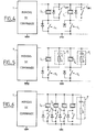
- FIGS. 5 and 6 represent two variants of a third embodiment of the device according to the invention, wherein the damping means are made by a passive circuit RC type.
- P i is connected in parallel on each piezoelectric injector I i .
- the energy stored in each selected injector, when controlling the injection by the means 1, is dissipated in the RC circuit at the end of this piloting.
- a single passive circuit RC is connected in parallel with the set of N branches, each comprising an injector I i and its selection switch S i .
- the energy that it has stored is dissipated in the passive circuit RC, referenced P, which thus dampens its free oscillations.
- the invention proposes another embodiment of the control device when it comprises injection control means made by a bridge assembly and a transformer ( figure 7 ).
- the bridge consists of two arms connected in parallel to the terminals of a DC voltage source, and each constituted by two bridge switches P 1 and P 3 , respectively P 2 and P 4 , in series and controllable alternately, whose points respective media J 1 and J 2 are connected to the two terminals of the primary winding L 1 of the transformer.
- the secondary winding L 2 is connected in parallel with the branches comprising the injectors and their selection switches S i .
- the damping means of the free oscillations of the injectors at the end of excitation are realized by the simultaneous closing of the first bridge switches P 1 and P 2 of each arm, in order to connect the two terminals of the primary winding L 1 to one of the terminals B +, for example, of the DC voltage source E, which short-circuits the secondary winding L 2 and makes it possible to damp the free oscillations of the injectors successively selected because the energy is going to dissipate in the conduction resistors of the switches.
- This damping could also be obtained by closing the two second bridge switches P 3 and P 4 of each arm which would connect the primary winding L 1 to the other terminal B- of the voltage source E. These two bridge switches are again open simultaneously before a new excitation cycle of another injector.
- a last embodiment of the invention is shown on the figure 8 and consists in placing in anti-parallel on each piezoelectric actuator I i a diode D i , which allows damping in one direction of the current. They make it possible to reduce the amplitude of the oscillation in tension, and thus the quantity ejected by the piezoelectric injector.
Landscapes
- Engineering & Computer Science (AREA)
- Chemical & Material Sciences (AREA)
- Combustion & Propulsion (AREA)
- Mechanical Engineering (AREA)
- General Engineering & Computer Science (AREA)
- Fuel-Injection Apparatus (AREA)
- Electrical Control Of Air Or Fuel Supplied To Internal-Combustion Engine (AREA)
- Electrically Driven Valve-Operating Means (AREA)
Claims (7)
- Steuervorrichtung mehrerer ausgehend von einem Kontrollrechner und von einer Gleichspannungsquelle elektronisch gesteuerter piezoelektrischer Ultraschallaktoren (Ii), die elektronische Steuereinrichtungen (1) der Aktoren aufweist, die von der Gleichspannungsquelle gespeist werden und ein Wechselspannungssignal zur Anregung jedes Aktors (Ii) liefern, der von einem mit dem Aktor (Ii) in Reihe geschalteten steuerbaren Schalter (Si) ausgewählt wird, dadurch gekennzeichnet, dass sie außerdem Einrichtungen zur Dämpfung der freien Schwingungen des Aktors, die einen Einspritzwiderstand hervorrufen, durch Kurzschließen jedes ausgewählten piezoelektrischen Aktors (Ii) nach dem Abschalten des Anregungssignals aufweist.
- Steuervorrichtung nach Anspruch 1, dadurch gekennzeichnet, dass die Kurzschlusseinrichtungen aus einerseits einem ersten Schalter (Sam), der mit den je aus einem piezoelektrischen Aktor (Ii) in Reihe mit einem steuerbaren Auswahlschalter (Si) bestehenden Zweigen parallelgeschaltet ist, die selbst zueinander parallelgeschaltet sind, und andererseits einem zweiten Schalter (Sinj) bestehen, der die Steuereinrichtungen (1) der Aktoren mit dem Verbindungspunkt (J) der Aktoren verbindet.
- Steuervorrichtung nach Anspruch 1, dadurch gekennzeichnet, dass die Kurzschlusseinrichtungen aus einem mit jedem der piezoelektrischen Aktoren (Ii) parallelgeschalteten Schalter (Sami) bestehen, der zwischen ihrem Verbindungspunkt (J) und dem Auswahlschalter (Si) des Aktors angeschlossen ist.
- Steuervorrichtung nach Anspruch 1, dadurch gekennzeichnet, dass die Kurzschlusseinrichtungen aus einer passiven Dämpfungsschaltung vom Typ RC (P) bestehen, die mit der Gesamtheit der einen piezoelektrischen Aktor (Ii) in Reihe mit einem Auswahlschalter (Si) enthaltenden Zweige parallelgeschaltet ist, die selbst zueinander parallelgeschaltet sind.
- Steuervorrichtung nach Anspruch 1, dadurch gekennzeichnet, dass die Kurzschlusseinrichtungen aus einer passiven Dämpfungsschaltung vom Typ RC (Pi) bestehen, die mit jedem der einen piezoelektrischen Aktor (Ii) in Reihe mit einem Auswahlschalter (Si) enthaltenden Zweige parallelgeschaltet ist, die selbst zueinander parallelgeschaltet sind.
- Steuervorrichtung nach Anspruch 1, dadurch gekennzeichnet, dass in dem Fall, in dem die Steuereinrichtungen (1) aus einer Brückenschaltung mit einem Transformator bestehen, dessen Mittenlast die Primärwicklung (L1) des Transformators ist, die ausgehend von zwei Armen hergestellt wird, die mit den Klemmen der Gleichspannungsquelle (E) parallelgeschaltet sind und je aus zwei in Reihe geschalteten Brückenschaltern (P1 und P3, P2 und P4) bestehen, die abwechselnd steuerbar sind, deren jeweilige Mittenpunkte (J1, J2) mit den zwei Klemmen der Primärwicklung des Transformators verbunden sind, die Kurzschlusseinrichtungen von den Paaren der ersten (P1, P2), bzw. der zweiten Schalter (P3, P4) jedes Arms gebildet werden, die gesteuert werden, um so die zwei Klemmen der Primärwicklung mit der positiven bzw. negativen Klemme der Gleichspannungsquelle zu verbinden, um die Sekundärwicklung (L2) des Transformators kurzzuschließen.
- Steuervorrichtung nach Anspruch 1, dadurch gekennzeichnet, dass die Kurzschlusseinrichtungen aus einer auf jedem piezoelektrischen Aktor (Ii) antiparallel angeordneten Diode (Di) bestehen, die die Dämpfung nur in einer Stromrichtung erlaubt, indem die Amplitude der Spannungsschwingung des piezoelektrischen Einspritzventils verringert wird.
Applications Claiming Priority (2)
| Application Number | Priority Date | Filing Date | Title |
|---|---|---|---|
| FR0312804 | 2003-10-31 | ||
| FR0312804A FR2861920B1 (fr) | 2003-10-31 | 2003-10-31 | Dispositif de commande d'actionneurs piezo-electriques ultrasonores |
Publications (2)
| Publication Number | Publication Date |
|---|---|
| EP1528605A1 EP1528605A1 (de) | 2005-05-04 |
| EP1528605B1 true EP1528605B1 (de) | 2009-12-09 |
Family
ID=34400893
Family Applications (1)
| Application Number | Title | Priority Date | Filing Date |
|---|---|---|---|
| EP04300740A Expired - Lifetime EP1528605B1 (de) | 2003-10-31 | 2004-10-28 | Steuervorrichtung für piezoelektrische Ultraschallaktoren |
Country Status (4)
| Country | Link |
|---|---|
| EP (1) | EP1528605B1 (de) |
| AT (1) | ATE451724T1 (de) |
| DE (1) | DE602004024491D1 (de) |
| FR (1) | FR2861920B1 (de) |
Families Citing this family (3)
| Publication number | Priority date | Publication date | Assignee | Title |
|---|---|---|---|---|
| FR2879255B1 (fr) * | 2004-12-14 | 2010-02-26 | Renault Sas | Procede de pilotage electronique d'un actionneur piezo-electrique ultrasonore |
| FR2901575B1 (fr) * | 2006-05-24 | 2012-08-17 | Renault Sas | Dispositif de commande d'un injecteur piezo-electrique ultrasonore |
| RU2451933C1 (ru) * | 2011-01-21 | 2012-05-27 | Владимир Яковлевич Грошев | Способ демпфирования пьезоэлектрических излучателей и устройство для его осуществления |
Family Cites Families (5)
| Publication number | Priority date | Publication date | Assignee | Title |
|---|---|---|---|---|
| DE19709717C1 (de) * | 1997-03-10 | 1998-09-24 | Siemens Ag | Vorrichtung und Verfahren zum Ansteuern wenigstens eines kapazitiven Stellgliedes |
| DE19711903C2 (de) * | 1997-03-21 | 1999-03-18 | Siemens Ag | Vorrichtung und Verfahren zum Ansteuern eines piezogesteuerten Kraftstoffeinspritzventils |
| DE19854306A1 (de) * | 1998-11-25 | 2000-06-08 | Bosch Gmbh Robert | Steller mit kapazitivem Element |
| JP2001251874A (ja) * | 2000-03-06 | 2001-09-14 | Nikon Corp | 振動アクチュエータの駆動装置 |
| FR2831727A1 (fr) * | 2001-10-30 | 2003-05-02 | Renault | Dispositif de commande d'un actuateur piezo-electrique ultrasonore pilote electroniquement, et son procede de mise en oeuvre |
-
2003
- 2003-10-31 FR FR0312804A patent/FR2861920B1/fr not_active Expired - Fee Related
-
2004
- 2004-10-28 EP EP04300740A patent/EP1528605B1/de not_active Expired - Lifetime
- 2004-10-28 DE DE602004024491T patent/DE602004024491D1/de not_active Expired - Lifetime
- 2004-10-28 AT AT04300740T patent/ATE451724T1/de not_active IP Right Cessation
Also Published As
| Publication number | Publication date |
|---|---|
| EP1528605A1 (de) | 2005-05-04 |
| ATE451724T1 (de) | 2009-12-15 |
| FR2861920B1 (fr) | 2007-08-10 |
| DE602004024491D1 (de) | 2010-01-21 |
| FR2861920A1 (fr) | 2005-05-06 |
Similar Documents
| Publication | Publication Date | Title |
|---|---|---|
| EP2005491B1 (de) | Vorrichtung und verfahren zum antrieb von mehreren ultraschall-piezoaktoren | |
| WO2004001868A2 (fr) | Procede de pilotage electronique d’un dispositif de commande d’un actuateur piezo-electrique ultrasonore | |
| EP1528605B1 (de) | Steuervorrichtung für piezoelektrische Ultraschallaktoren | |
| EP1446843A2 (de) | Elektronische steuervorrichtung für einen piezoelektrischen ultraschallaktuator und deren betriebsverfahren | |
| EP1067608B1 (de) | Anordnung und Steuerschaltung eines piezoelektrisches Antriebs | |
| WO2003038918A2 (fr) | Dispositif de commande d'un actuateur piezo-electrique | |
| EP1422764B1 (de) | Steuervorrichtung für einen piezoelektrischen Ultraschallaktuator und Betriebsverfahren | |
| EP1469183B1 (de) | Steuervorrichtung für einen piezoelektrischen Ultraschallaktuator sowie Betriebsverfahren | |
| FR2923664A1 (fr) | Generateur de train d'impulsion de tension, application a la commande d'injecteur piozoelectrique ultrasonore. | |
| EP1471239A1 (de) | Steuervorrichtung für einen piezoelektrischen Ultraschallaktuator und Betriebsverfahren | |
| EP2024627A1 (de) | Vorrichtung zur steuerung eines piezoelektrischen ultraschallinjektors | |
| EP2870614A1 (de) | Elektrische schaltung zur anregung von mindestens einem elektromagnet | |
| FR2879255A1 (fr) | Procede de pilotage electronique d'un actionneur piezo-electrique ultrasonore | |
| EP1828584B1 (de) | Vorrichtung zur elektronischen steuerung von piezoelektrischen ultraschallaktuatoren | |
| FR2763627A1 (fr) | Serrure electrique de portiere de vehicule automobile comportant un moteur piezo-electrique | |
| FR2861919A1 (fr) | Dispositif de commande de plusieurs actionneurs piezo-electriques ultrasonores | |
| FR2798536A1 (fr) | Procede et dispositif de commande d'au moins un organe de de reglage capacitif | |
| CH495005A (fr) | Pièce d'horlogerie électrique comportant un ensemble balancier-spiral commandé par un transducteur | |
| EP1420156A2 (de) | Ansteuerschaltung für Kraftstoffinjektoren eines Fahrzeugs | |
| FR2879256A1 (fr) | Dispositif de commande electronique d'actionneurs piezo-electriques | |
| EP1647693B1 (de) | Verfahren zur Ansteuerung einer Steuerschaltung und Betätigungseinrichtung | |
| WO2006042997A1 (fr) | Procede et dispositif de pilotage d'injecteurs piezo-electriques ultrasonores pour moteur thermique | |
| EP1670078A1 (de) | Steuerverfahren einer Steuerschaltung für piezostriktive oder magnetostriktive Aktoren | |
| EP0323318A1 (de) | Gerät zur Steuerung und Prüfung von Kraftstoffeinspritzventilen eines Mehrzylinder-Verbrennungsmotors, insbesondere eines Zweitaktmotors |
Legal Events
| Date | Code | Title | Description |
|---|---|---|---|
| PUAI | Public reference made under article 153(3) epc to a published international application that has entered the european phase |
Free format text: ORIGINAL CODE: 0009012 |
|
| AK | Designated contracting states |
Kind code of ref document: A1 Designated state(s): AT BE BG CH CY CZ DE DK EE ES FI FR GB GR HU IE IT LI LU MC NL PL PT RO SE SI SK TR |
|
| AX | Request for extension of the european patent |
Extension state: AL HR LT LV MK |
|
| 17P | Request for examination filed |
Effective date: 20051024 |
|
| AKX | Designation fees paid |
Designated state(s): AT BE BG CH CY CZ DE DK EE ES FI FR GB GR HU IE IT LI LU MC NL PL PT RO SE SI SK TR |
|
| 17Q | First examination report despatched |
Effective date: 20070504 |
|
| GRAP | Despatch of communication of intention to grant a patent |
Free format text: ORIGINAL CODE: EPIDOSNIGR1 |
|
| GRAS | Grant fee paid |
Free format text: ORIGINAL CODE: EPIDOSNIGR3 |
|
| GRAA | (expected) grant |
Free format text: ORIGINAL CODE: 0009210 |
|
| AK | Designated contracting states |
Kind code of ref document: B1 Designated state(s): AT BE BG CH CY CZ DE DK EE ES FI FR GB GR HU IE IT LI LU MC NL PL PT RO SE SI SK TR |
|
| REG | Reference to a national code |
Ref country code: GB Ref legal event code: FG4D Free format text: NOT ENGLISH |
|
| REG | Reference to a national code |
Ref country code: CH Ref legal event code: EP |
|
| REG | Reference to a national code |
Ref country code: IE Ref legal event code: FG4D |
|
| REF | Corresponds to: |
Ref document number: 602004024491 Country of ref document: DE Date of ref document: 20100121 Kind code of ref document: P |
|
| REG | Reference to a national code |
Ref country code: NL Ref legal event code: VDEP Effective date: 20091209 |
|
| PG25 | Lapsed in a contracting state [announced via postgrant information from national office to epo] |
Ref country code: SE Free format text: LAPSE BECAUSE OF FAILURE TO SUBMIT A TRANSLATION OF THE DESCRIPTION OR TO PAY THE FEE WITHIN THE PRESCRIBED TIME-LIMIT Effective date: 20091209 Ref country code: FI Free format text: LAPSE BECAUSE OF FAILURE TO SUBMIT A TRANSLATION OF THE DESCRIPTION OR TO PAY THE FEE WITHIN THE PRESCRIBED TIME-LIMIT Effective date: 20091209 |
|
| PG25 | Lapsed in a contracting state [announced via postgrant information from national office to epo] |
Ref country code: SI Free format text: LAPSE BECAUSE OF FAILURE TO SUBMIT A TRANSLATION OF THE DESCRIPTION OR TO PAY THE FEE WITHIN THE PRESCRIBED TIME-LIMIT Effective date: 20091209 Ref country code: PL Free format text: LAPSE BECAUSE OF FAILURE TO SUBMIT A TRANSLATION OF THE DESCRIPTION OR TO PAY THE FEE WITHIN THE PRESCRIBED TIME-LIMIT Effective date: 20091209 |
|
| PG25 | Lapsed in a contracting state [announced via postgrant information from national office to epo] |
Ref country code: AT Free format text: LAPSE BECAUSE OF FAILURE TO SUBMIT A TRANSLATION OF THE DESCRIPTION OR TO PAY THE FEE WITHIN THE PRESCRIBED TIME-LIMIT Effective date: 20091209 |
|
| REG | Reference to a national code |
Ref country code: IE Ref legal event code: FD4D |
|
| PG25 | Lapsed in a contracting state [announced via postgrant information from national office to epo] |
Ref country code: RO Free format text: LAPSE BECAUSE OF FAILURE TO SUBMIT A TRANSLATION OF THE DESCRIPTION OR TO PAY THE FEE WITHIN THE PRESCRIBED TIME-LIMIT Effective date: 20091209 Ref country code: PT Free format text: LAPSE BECAUSE OF FAILURE TO SUBMIT A TRANSLATION OF THE DESCRIPTION OR TO PAY THE FEE WITHIN THE PRESCRIBED TIME-LIMIT Effective date: 20100409 Ref country code: IE Free format text: LAPSE BECAUSE OF FAILURE TO SUBMIT A TRANSLATION OF THE DESCRIPTION OR TO PAY THE FEE WITHIN THE PRESCRIBED TIME-LIMIT Effective date: 20091209 Ref country code: BG Free format text: LAPSE BECAUSE OF FAILURE TO SUBMIT A TRANSLATION OF THE DESCRIPTION OR TO PAY THE FEE WITHIN THE PRESCRIBED TIME-LIMIT Effective date: 20100309 Ref country code: NL Free format text: LAPSE BECAUSE OF FAILURE TO SUBMIT A TRANSLATION OF THE DESCRIPTION OR TO PAY THE FEE WITHIN THE PRESCRIBED TIME-LIMIT Effective date: 20091209 Ref country code: ES Free format text: LAPSE BECAUSE OF FAILURE TO SUBMIT A TRANSLATION OF THE DESCRIPTION OR TO PAY THE FEE WITHIN THE PRESCRIBED TIME-LIMIT Effective date: 20100320 Ref country code: EE Free format text: LAPSE BECAUSE OF FAILURE TO SUBMIT A TRANSLATION OF THE DESCRIPTION OR TO PAY THE FEE WITHIN THE PRESCRIBED TIME-LIMIT Effective date: 20091209 |
|
| PG25 | Lapsed in a contracting state [announced via postgrant information from national office to epo] |
Ref country code: CZ Free format text: LAPSE BECAUSE OF FAILURE TO SUBMIT A TRANSLATION OF THE DESCRIPTION OR TO PAY THE FEE WITHIN THE PRESCRIBED TIME-LIMIT Effective date: 20091209 Ref country code: SK Free format text: LAPSE BECAUSE OF FAILURE TO SUBMIT A TRANSLATION OF THE DESCRIPTION OR TO PAY THE FEE WITHIN THE PRESCRIBED TIME-LIMIT Effective date: 20091209 |
|
| PLBE | No opposition filed within time limit |
Free format text: ORIGINAL CODE: 0009261 |
|
| STAA | Information on the status of an ep patent application or granted ep patent |
Free format text: STATUS: NO OPPOSITION FILED WITHIN TIME LIMIT |
|
| PG25 | Lapsed in a contracting state [announced via postgrant information from national office to epo] |
Ref country code: CY Free format text: LAPSE BECAUSE OF FAILURE TO SUBMIT A TRANSLATION OF THE DESCRIPTION OR TO PAY THE FEE WITHIN THE PRESCRIBED TIME-LIMIT Effective date: 20091209 Ref country code: GR Free format text: LAPSE BECAUSE OF FAILURE TO SUBMIT A TRANSLATION OF THE DESCRIPTION OR TO PAY THE FEE WITHIN THE PRESCRIBED TIME-LIMIT Effective date: 20100310 |
|
| 26N | No opposition filed |
Effective date: 20100910 |
|
| PG25 | Lapsed in a contracting state [announced via postgrant information from national office to epo] |
Ref country code: DK Free format text: LAPSE BECAUSE OF FAILURE TO SUBMIT A TRANSLATION OF THE DESCRIPTION OR TO PAY THE FEE WITHIN THE PRESCRIBED TIME-LIMIT Effective date: 20091209 |
|
| PG25 | Lapsed in a contracting state [announced via postgrant information from national office to epo] |
Ref country code: IT Free format text: LAPSE BECAUSE OF FAILURE TO SUBMIT A TRANSLATION OF THE DESCRIPTION OR TO PAY THE FEE WITHIN THE PRESCRIBED TIME-LIMIT Effective date: 20091209 |
|
| BERE | Be: lapsed |
Owner name: RENAULT S.A.S. Effective date: 20101031 |
|
| PG25 | Lapsed in a contracting state [announced via postgrant information from national office to epo] |
Ref country code: MC Free format text: LAPSE BECAUSE OF NON-PAYMENT OF DUE FEES Effective date: 20101031 |
|
| REG | Reference to a national code |
Ref country code: CH Ref legal event code: PL |
|
| PG25 | Lapsed in a contracting state [announced via postgrant information from national office to epo] |
Ref country code: CH Free format text: LAPSE BECAUSE OF NON-PAYMENT OF DUE FEES Effective date: 20101031 Ref country code: LI Free format text: LAPSE BECAUSE OF NON-PAYMENT OF DUE FEES Effective date: 20101031 |
|
| PG25 | Lapsed in a contracting state [announced via postgrant information from national office to epo] |
Ref country code: BE Free format text: LAPSE BECAUSE OF NON-PAYMENT OF DUE FEES Effective date: 20101031 |
|
| PG25 | Lapsed in a contracting state [announced via postgrant information from national office to epo] |
Ref country code: LU Free format text: LAPSE BECAUSE OF NON-PAYMENT OF DUE FEES Effective date: 20101028 Ref country code: HU Free format text: LAPSE BECAUSE OF FAILURE TO SUBMIT A TRANSLATION OF THE DESCRIPTION OR TO PAY THE FEE WITHIN THE PRESCRIBED TIME-LIMIT Effective date: 20100610 |
|
| PG25 | Lapsed in a contracting state [announced via postgrant information from national office to epo] |
Ref country code: TR Free format text: LAPSE BECAUSE OF FAILURE TO SUBMIT A TRANSLATION OF THE DESCRIPTION OR TO PAY THE FEE WITHIN THE PRESCRIBED TIME-LIMIT Effective date: 20091209 |
|
| REG | Reference to a national code |
Ref country code: FR Ref legal event code: PLFP Year of fee payment: 12 |
|
| REG | Reference to a national code |
Ref country code: FR Ref legal event code: PLFP Year of fee payment: 13 |
|
| REG | Reference to a national code |
Ref country code: FR Ref legal event code: PLFP Year of fee payment: 14 |
|
| PGFP | Annual fee paid to national office [announced via postgrant information from national office to epo] |
Ref country code: FR Payment date: 20171024 Year of fee payment: 14 Ref country code: DE Payment date: 20171019 Year of fee payment: 14 |
|
| PGFP | Annual fee paid to national office [announced via postgrant information from national office to epo] |
Ref country code: GB Payment date: 20171019 Year of fee payment: 14 |
|
| REG | Reference to a national code |
Ref country code: DE Ref legal event code: R119 Ref document number: 602004024491 Country of ref document: DE |
|
| GBPC | Gb: european patent ceased through non-payment of renewal fee |
Effective date: 20181028 |
|
| PG25 | Lapsed in a contracting state [announced via postgrant information from national office to epo] |
Ref country code: DE Free format text: LAPSE BECAUSE OF NON-PAYMENT OF DUE FEES Effective date: 20190501 |
|
| PG25 | Lapsed in a contracting state [announced via postgrant information from national office to epo] |
Ref country code: FR Free format text: LAPSE BECAUSE OF NON-PAYMENT OF DUE FEES Effective date: 20181031 |
|
| PG25 | Lapsed in a contracting state [announced via postgrant information from national office to epo] |
Ref country code: GB Free format text: LAPSE BECAUSE OF NON-PAYMENT OF DUE FEES Effective date: 20181028 |