EP1537022B1 - Verfahren zum befestigen von einem clip-verschluss auf einem produkt - Google Patents
Verfahren zum befestigen von einem clip-verschluss auf einem produkt Download PDFInfo
- Publication number
- EP1537022B1 EP1537022B1 EP03736942A EP03736942A EP1537022B1 EP 1537022 B1 EP1537022 B1 EP 1537022B1 EP 03736942 A EP03736942 A EP 03736942A EP 03736942 A EP03736942 A EP 03736942A EP 1537022 B1 EP1537022 B1 EP 1537022B1
- Authority
- EP
- European Patent Office
- Prior art keywords
- clip
- pouch
- clip member
- hinge
- fastening
- Prior art date
- Legal status (The legal status is an assumption and is not a legal conclusion. Google has not performed a legal analysis and makes no representation as to the accuracy of the status listed.)
- Expired - Lifetime
Links
Images

Classifications
-
- B—PERFORMING OPERATIONS; TRANSPORTING
- B65—CONVEYING; PACKING; STORING; HANDLING THIN OR FILAMENTARY MATERIAL
- B65B—MACHINES, APPARATUS OR DEVICES FOR, OR METHODS OF, PACKAGING ARTICLES OR MATERIALS; UNPACKING
- B65B51/00—Devices for, or methods of, sealing or securing package folds or closures; Devices for gathering or twisting wrappers, or necks of bags
- B65B51/04—Applying separate sealing or securing members, e.g. clips
-
- B—PERFORMING OPERATIONS; TRANSPORTING
- B65—CONVEYING; PACKING; STORING; HANDLING THIN OR FILAMENTARY MATERIAL
- B65D—CONTAINERS FOR STORAGE OR TRANSPORT OF ARTICLES OR MATERIALS, e.g. BAGS, BARRELS, BOTTLES, BOXES, CANS, CARTONS, CRATES, DRUMS, JARS, TANKS, HOPPERS, FORWARDING CONTAINERS; ACCESSORIES, CLOSURES, OR FITTINGS THEREFOR; PACKAGING ELEMENTS; PACKAGES
- B65D33/00—Details of, or accessories for, sacks or bags
- B65D33/16—End- or aperture-closing arrangements or devices
- B65D33/1658—Elements for flattening or folding the mouth portion
- B65D33/1675—Hinged clips
-
- B—PERFORMING OPERATIONS; TRANSPORTING
- B31—MAKING ARTICLES OF PAPER, CARDBOARD OR MATERIAL WORKED IN A MANNER ANALOGOUS TO PAPER; WORKING PAPER, CARDBOARD OR MATERIAL WORKED IN A MANNER ANALOGOUS TO PAPER
- B31B—MAKING CONTAINERS OF PAPER, CARDBOARD OR MATERIAL WORKED IN A MANNER ANALOGOUS TO PAPER
- B31B70/00—Making flexible containers, e.g. envelopes or bags
- B31B70/74—Auxiliary operations
- B31B70/81—Forming or attaching accessories, e.g. opening devices, closures or tear strings
Definitions
- the present invention relates to both a process for automating the attachment of a clip or closure device to a product.
- pouches containing fluids are often used for a variety of purposes. For instance, saline solutions, medical wastes, and chemical hot and cold packs are considered but a few of the uses. Similar pouches are used for phase change materials, one such example being that of an ice pack.
- a clip that contains some form of clamping mechanism to capture the pouch.
- a hinge is often disposed in some manner on the clip enabling the clamping mechanism to move selectively from an open to a closed position.
- the clip is secured or maintained in a clamped position by the use of a latch mechanism.
- hinge commonly used to join the two clamping mechanisms or clamping jaws is a strap-like hinge, known in the art as a "living hinge”. See for example US 5 735 022 .
- this construction is not easily adapted to the automated sorting and feeding of the clip and subsequent attachment of the clip to the product. Due to the inherent flexibility of the living hinge, the clamping surfaces move with respect to one another when the clip is moved through an automated assembly process. This results in a random orientation of the clip making it impractical for an automated assembly process.
- one aspect of the present invention discloses a process for automating the positioning and fastening of a clip to a pouch.
- a first clip member having ends, a clamping surface, a latching component, and a hinge component is provided.
- the hinge component includes a necked region which is disposed proximate to one of the ends of the clip member.
- a second clip member also having a clamping surface, a latching component, and a hinge component is provided as well.
- Each of the clip members are loaded into feed mechanisms and mechanically manipulated into desired orientations.
- the clip members are dispensed in aligned, spaced apart relation with their clamping surfaces, latching components, and hinge components disposed one toward the other.
- a pouch having a plurality of sealed sides and an open end is positioned between the clamping surfaces and the clip members are joined together by fastening the hinge component of the first clip member to the hinge component of the second clip member.
- the clip serves to capture and retain the pouch.
- the clip may be fastened in some manner to the pouch.
- a flexible container having an interior, an exterior, and at least one opening from the exterior to the interior is provided along with a first and a second clip member having a clamping surface, a latching component, and a hinge component.
- Each is continuously moved until the first and the second clip members are in aligned, spaced apart relation with the clamping surfaces, latching components, and hinge components disposed one toward the other and the container is positioned between the clamping surfaces of the clip members.
- the clip members are joined semi-permanently together by fastening the hinge component of the first clip member to the hinge component of the second clip member. This results in a clip with a hinge at one end and a releasable latch at another end.
- the releasable latch being operable by fastening and unfastening of the latching components.
- the clip serves to capture and retain the flexible container between the clamping surfaces of the clip members for selectively opening and closing the opening to the interior of the container.
- the present invention discloses a refillable pouch and clip arrangement.
- a refillable pouch having a plurality of sealed sides and an open end is provided.
- First and second clip members each having a clamping surface, a latching component, and a hinge component are mechanically manipulated into a desired orientation.
- At least one of the hinge components of one of the clip members has a necked region proximate to one end.
- the necked region being a thin flexible portion of the respective clip member.
- the first and the second clip members are positioned in aligned, spaced apart relation with the clamping surfaces, latching components, and hinge components being disposed one toward the other.
- the pouch is disposed between the clamping surfaces proximate to the open end.
- the first and second clip members are fastened together by joining the hinge components to form a clip having a hinge end and a releasable latch end for capturing and retaining the pouch between the clamping surfaces of the clip members.
- the flexible neck hinging the first and second clip members together.
- the pouch has a plurality of sealed sides and an open end which is sealed against leakage by a clip.
- the clip serves to secure a portion of the pouch between clamping surfaces associated with the clip.
- the clip has two clip members which are rigidly joined at one end to form a connecting end.
- the clip also has a necked region disposed upon at least one of the clip members proximate to the connecting end. The necked region serves to hinge the clip selectively open and closed to selectively seal and unseal the pouch.
- the connecting end is formed by loading each clip member into a feed mechanism for subsequent mechanical manipulation and dispense into aligned, spaced apart relation with the pouch disposed between the individual clip members. This allows the ends to be rigidly joined and the clip can be subsequently fastened so that the pouch is positioned between the clamping surfaces.
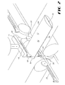
- the present invention provides a process for automating the assembly of a clip 10 with a product 12. Automating the assembly results in both an increase in the quantity of finished products available per unit of time and a per unit cost savings when compared to the costs associated with workers manually attaching the clips 10 to the product 12.
- a first clip member 14 having a clamping surface 16 disposed between a latching component 18 and a hinge component 20 is loaded into a first feed mechanism 22.
- a second clip member 24 having a clamping surface 26 disposed between a latching component 28 and a hinge component 30 is loaded into a second feed mechanism 32.
- Each of the clip members 14 and 24 are mechanically manipulated into a desired orientation. Manipulation of the clip members may be accomplished by any suitable manner well known in the art, including the use of vibration, centrifugal force, gravity, etc. As an alternative, the clip members 14 and 24 may be preoriented at the time they are loaded into their respective feeding mechanisms.
- the feed mechanisms 22 and 32 in some embodiments may be bowl-type feeders. In other embodiments, the feed mechanisms may be adapted to accept cartridges (not shown) containing preoriented clip members 14 and/or 24 for loading. Other embodiments may include a single feed mechanism capable of sorting and properly orienting each clip member prior to assembly. Therefore, it should be understood that the specific form of feed mechanism or the manner in which it functions is not critical to the invention at hand. As such the feed mechanisms may take on any form understood in the art as being capable of achieving the task described.
- the first clip member 14 is moved in a first direction 34 on a conveyor mechanism 36.
- the second clip member 24 is moved in a second direction 38 on a conveyor mechanism 40.
- the directions 34 and 38 are depicted as differing, it should be understood that there is no requirement that they differ. In fact, some embodiments would locate the first feed mechanism 22 proximate to the second feed mechanism 24. This arrangement makes it possible for the conveyor mechanisms 36 and 40 to operate such that feed directions 34 and 38 are the same.
- the product 12 is moved in a third direction 42 along a conveyor mechanism 44.
- Each component, the first clip member 14, the second clip member 24, and the product 12 are continuously moved along their respective conveyor mechanisms in their respective directions.
- the clip members 14 and 24 and/or the product 12 may rest upon their respective conveyor mechanisms 36, 40, and 44 by gravity.
- any one of these components may be transported in its respective direction by means of vacuum attachment.
- the transport of the components as well as their direction of travel may be accomplished by any suitable manner well known in the art.
- each component reaches a desired location where the first and second clip members 14 and 24 are positioned in aligned, spaced apart relation with the clamping surfaces 16 and 26 disposed toward one another.
- the clip members 14 and 24 also are positioned in such a manner so that the latching components 18 and 28 as well as the hinge components 20 and 30 are also disposed one toward the other.
- the relative orientation of one clip member with respect to the other enables the clip members 14 and 24 to be joined together to form the clip 10.
- the first and second clip members 14 and 24 are joined together by fastening the hinge component 20 of the first clip member 14 with the hinge component 30 of the second clip member 24.
- the design of the hinge components 20 and 30 are such that once joined they are permanently fastened together. This may be accomplished by among other means, the application of an adhesive, ultrasonic welding, or heat bonding of one material to the other.
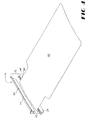
- the hinge components 20 and 30 are semi-permanently fastened to one another. This may be accomplished in any way known to those skilled in the art, including through the use of fasteners 46 such as shown in FIG. 4 .
- the fasteners 46 may be configured in a number of possible configurations such as bayonet-type fasteners, snaps, clips, in addition to other male-to-female connections. Once fastened, these semi-permanent types of fasteners 46 are designed to remain in a fastened condition. However, should there exist reason to separate them, the process of separating them should not destroy their integrity.
- the clip 10 is provided with a hinge 48. Additionally, the latching components 18 and 28 interact with one another so that in combination, they form a latch 50.
- the latch 50 is adapted to alternatively latch or unlatch the clip 10. As such, the product 12 once situated between the clamping surfaces 16 and 26 of the clip 10 may be retained by the clip 10.
- the latch 50 may not be immediately secured. It may be desirable to allow the clip 10 to remain in an open, unlatched position. As such, another practical configuration allows the clip 10 to be adhered either permanently or temporarily to the product 12. For instance, the clip 10 can be adhered through the application of an adhesive tape (not shown) to at least one portion of the clip 10 so as to secure it to the product 12. Alternatively, a hot melt or cold adhesive can be applied in the same manner to secure the clip 10 to the product 12.
- the product 12 can be made in limitless configurations.
- the product 12 may be a length of material such as a flexible fabric made of natural or synthetic fibers.
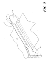
- Other embodiments such as shown in FIG. 2 envision the product 12 to be in the form of a container 52 having at least one open end 54 and a plurality of sealed sides 56.
- a container 52 may be constructed of a material capable of containing fluids, such as liquids.
- the container 52 may be adapted to contain fluids under pressure. As such, the design of the clip 10 should be capable of securing the container against leakage.
- Clips 10 and containers 52 of the sort described are suitable for use in the medical industry among other fields.
- containers of the present construction are adapted for use as saline bags, colostomy pouches, reusable ice packs and the like.
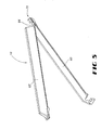
- the clip 10 may be configured into a blade and trough arrangement. That is, in one possible configuration, one of the clip members 14 or 24 is configured into the shape of a substantially planar blade 60. As such, the remaining clip member is configured into a trough 62 within which the blade 60 resides. This trough and blade arrangement serves as the clamping surfaces 16 and 26 earlier described. As such, the ice pack 58 is captured between the blade 60 and trough 62.
- a necked region 66 may be provided proximate to one end of either clip member 14 and/or 24.
- the necked region 66 may be made sufficiently thin and flexible as compared to the remainder of the clip member upon which it is located so as to force the necked region 66 to serve as a flexible hinge once the clip 10 is assembled.
- the clip 10 is assembled by joining the blade 60 to the trough 62 at ends 70.
- the necked region 66 enables the clip 10 to open and close even though the first and second clip members 14 and 24 are otherwise fastened together at one end.
- the necked region 66 enables the clip to hinge in substantially one plane.
- the necked region 66 can be thinned in either thickness, width, or both when compared to the remainder of the clip member 14 and/or 24.
Landscapes
- Engineering & Computer Science (AREA)
- Mechanical Engineering (AREA)
- Making Paper Articles (AREA)
- Bag Frames (AREA)
- Package Closures (AREA)
Claims (14)
- Ein Verfahren zum Automatisieren des Positionierens und Befestigens eines Clips (10) an einem Beutel (12), das umfasst:Bereitstellen eines ersten Clipelements (14), das Enden, eine Klemmfläche (16), eine verschließende Komponente (18) und eine Gelenkkomponente (20), die einen verjüngten Bereich umfasst, der nahe einem der Enden angeordnet ist, aufweist;Bereitstellen eines zweiten Clipelements (24), das eine Klemmfläche (26), eine verschließende Komponente (28) und eine Gelenkkomponente (30) aufweist;Laden des ersten Clipelements in einen ersten Zuführmechanismus (22);Laden des zweiten Clipelements in einen zweiten Zuführmechanismus (32);mechanisches Manipulieren des ersten Clipelements innerhalb des ersten Zuführmechanismus in eine gewünschte Ausrichtung;mechanisches Manipulieren des zweiten Clipelements innerhalb des zweiten Zuführmechanismus in eine gewünschte Ausrichtung;Bereitstellen eines Beutels (12), der eine Mehrzahl an versiegelten Seiten und ein offenes Ende besitzt;Ausgeben des ersten und des zweiten Clipelements in aneinander ausgerichteter, voneinander beabstandeter Beziehung, so dass die Klemmflächen eine der anderen zugewandt angeordnet sind und die verschließenden Komponenten und die Gelenkkomponenten jeweils eine der anderen zugewandt angeordnet sind;Positionieren des Beutels an einer Stelle nahe dem offenen Ende zwischen den Klemmflächen des ersten und des zweiten Clipelements;Verbinden des ersten und des zweiten Clipelements durch Befestigen der Gelenkkomponente des ersten Clipelements an der Gelenkkomponente des zweiten Clipelements, wodurch ein Clip gebildet wird, der an dem verjüngten Bereich angelenkt ist, und der einen lösbaren Verschluss besitzt, der durch das wahlweise Schließen und Lösen der verschließenden Komponenten bedienbar ist, wobei der Clip für das Erfassen und Festhalten des Beutels zwischen den Klemmflächen der Clipelemente ausgebildet ist; undBefestigen des zusammengesetzten Clips an dem Beutel.
- Das Verfahren von Anspruch 1, in dem der Beutel für die Verwendung auf einem medizinischen Gebiet geeignet ist.
- Das Verfahren von Anspruch 1, in dem der Beutel ein Eisbeutel ist.
- Das Verfahren von Anspruch 1, in dem der Beutel dazu ausgebildet ist, eine Flüssigkeit zu enthalten.
- Das Verfahren von Anspruch 1, in dem die mechanische Manipulation der Clipelemente durch eine Ausrichtung durch Vibrationen erreicht wird.
- Das Verfahren von Anspruch 1, in dem die mechanische Manipulation der Clipelemente durch eine Zentrifugalkraft erreicht wird.
- Das Verfahren von Anspruch 1, in dem die Clipelemente zuvor in Kassetten geladen werden, die eine Mehrzahl solcher Clipelemente enthalten.
- Das Verfahren von Anspruch 1, in dem das Befestigen der Gelenkkomponenten durch Ultraschall - Bondieren erreicht wird.
- Das Verfahren von Anspruch 1, in dem das Befestigen der Gelenkkomponenten durch die Anwendung von Wärme erreicht wird.
- Das Verfahren von Anspruch 1, in dem das Befestigen der Gelenkkomponenten durch das Verbinden eines männlichen Verbindungselements und eines weiblichen Verbindungselements erreicht wird.
- Das Verfahren von Anspruch 1, das weiterhin das Befestigen zumindest eines Clipelements an dem Beutel umfasst.
- Das Verfahren von Anspruch 11, weiterhin ein Klebeband zum Befestigen des zumindest einen Clipelements an dem Beutel umfassend.
- Das Verfahren von Anspruch 11, weiterhin einen Klebstoff zum Befestigen des zumindest einen Clipelements an dem Beutel umfassend.
- Das Verfahren von Anspruch 13, in dem der Klebstoff ein Heißkleber ist.
Applications Claiming Priority (3)
| Application Number | Priority Date | Filing Date | Title |
|---|---|---|---|
| US243394 | 1999-02-01 | ||
| US10/243,394 US6959523B2 (en) | 2002-09-13 | 2002-09-13 | Process for automating the attachment of a clip to a product |
| PCT/US2003/018076 WO2004024564A1 (en) | 2002-09-13 | 2003-06-06 | A process for automating the attachment of a clip to a product |
Publications (2)
| Publication Number | Publication Date |
|---|---|
| EP1537022A1 EP1537022A1 (de) | 2005-06-08 |
| EP1537022B1 true EP1537022B1 (de) | 2008-07-09 |
Family
ID=31991629
Family Applications (1)
| Application Number | Title | Priority Date | Filing Date |
|---|---|---|---|
| EP03736942A Expired - Lifetime EP1537022B1 (de) | 2002-09-13 | 2003-06-06 | Verfahren zum befestigen von einem clip-verschluss auf einem produkt |
Country Status (8)
| Country | Link |
|---|---|
| US (1) | US6959523B2 (de) |
| EP (1) | EP1537022B1 (de) |
| JP (1) | JP2005538866A (de) |
| AU (1) | AU2003237494A1 (de) |
| CA (1) | CA2498740A1 (de) |
| DE (1) | DE60322071D1 (de) |
| MX (1) | MXPA05002676A (de) |
| WO (1) | WO2004024564A1 (de) |
Families Citing this family (4)
| Publication number | Priority date | Publication date | Assignee | Title |
|---|---|---|---|---|
| DE102004018589B4 (de) * | 2004-04-16 | 2006-03-23 | Martin Ecker | Verschlusseinrichtung für einen Sack |
| US7810658B2 (en) * | 2006-01-26 | 2010-10-12 | Target Brands, Inc. | Display fixture accessories |
| US10843859B2 (en) * | 2019-02-12 | 2020-11-24 | 2677126 Ontario Inc. | Hermetic, hygienic, single-use packaging for consumable liquids |
| CA3229246A1 (en) * | 2021-08-20 | 2023-02-23 | Valka Ehf. | Handling installation, food processing installation, and method for handling food items |
Family Cites Families (80)
| Publication number | Priority date | Publication date | Assignee | Title |
|---|---|---|---|---|
| US381265A (en) | 1888-04-17 | Teeeitoey | ||
| US1459735A (en) | 1919-03-31 | 1923-06-26 | Schraders Son Inc | Closure for ice bags |
| US2589577A (en) | 1949-06-18 | 1952-03-18 | Pioneer Valley Plastics Compan | Ice pack formed of vinyl plastic sheeting |
| US2898744A (en) | 1956-06-15 | 1959-08-11 | Kwik Kold Of America Inc | Chemical freezing package |
| US3036506A (en) | 1959-06-15 | 1962-05-29 | Jr John H Andresen | Camera case for underwater photography |
| US3095291A (en) | 1961-05-12 | 1963-06-25 | Albert A Robbins | Cooling envelope with breakable diaphragm |
| US3149943A (en) | 1961-11-20 | 1964-09-22 | Martin R Amador | Chemical refrigerant package |
| US3171184A (en) | 1962-10-30 | 1965-03-02 | Posse Nils Lage Wilhelm | Clamp |
| US3259302A (en) | 1963-04-12 | 1966-07-05 | Rocchisani Pierre Xavier Marc | Closure device |
| US3247852A (en) | 1963-10-10 | 1966-04-26 | Hollister Inc | Umbilical cord clamp |
| US3461876A (en) | 1966-09-26 | 1969-08-19 | Abbott Lab | Tubing clamp |
| US3523534A (en) | 1967-04-05 | 1970-08-11 | Hollister Inc | Closure for drainage pouch |
| US3542032A (en) | 1968-03-22 | 1970-11-24 | Cramer Products Inc | Therapy package |
| US3551965A (en) | 1968-12-19 | 1971-01-05 | United Carr Inc | Clip |
| US3621539A (en) | 1970-02-27 | 1971-11-23 | Variform Plastics Inc | Bag sealer |
| US3669115A (en) | 1970-03-13 | 1972-06-13 | Rymel Corp | Surgical instrument with trunnioned hinge means |
| US3735765A (en) | 1971-03-18 | 1973-05-29 | D Ichelson | Method of closing lacerations and clamp therefor |
| US3785111A (en) | 1972-02-04 | 1974-01-15 | Schneider W | Method of forming containers and packages |
| US3807118A (en) | 1972-03-31 | 1974-04-30 | Schneider W | Method of forming a package |
| US3874042A (en) | 1973-01-22 | 1975-04-01 | Biospectrum Inc | Clamp for thin walled tubing |
| US3865117A (en) | 1973-06-25 | 1975-02-11 | Micro Bio Medics Inc | Thermal compress and method and apparatus for making the same |
| US3900989A (en) | 1973-11-29 | 1975-08-26 | Marvin L Weisenthal | Balloon clamp |
| US3950158A (en) | 1974-05-31 | 1976-04-13 | American Medical Products Company | Urea cold pack having an inner bag provided with a perforated seal |
| JPS5521604Y2 (de) | 1975-07-01 | 1980-05-24 | ||
| SE415296B (sv) | 1977-05-17 | 1980-09-22 | Jan Ingemar Neslund | Forfarande for behandling av kroppsvetskeprov for diagnostisk undersokning |
| US4212303A (en) | 1978-07-17 | 1980-07-15 | Hollister Incorporated | Umbilical cord clamp |
| US4506689A (en) | 1979-04-23 | 1985-03-26 | Fiddler Maurice K | Portable sun shelter |
| US4296529A (en) | 1979-07-11 | 1981-10-27 | Brown Stanley E | Bag sealing device |
| US4275485A (en) | 1979-12-10 | 1981-06-30 | Hutchison Charles L | Sealing devices |
| GB2076881B (en) | 1980-05-29 | 1984-02-15 | Kingsdown Medical Consultants | A clip |
| US4385950A (en) | 1980-09-05 | 1983-05-31 | Tecnol, Inc. | Small ice packs and method of manufacturing the same |
| US4523353A (en) | 1980-09-05 | 1985-06-18 | Tecnol, Inc. | Small ice packs and method of manufacturing the same |
| US4347848A (en) | 1980-09-05 | 1982-09-07 | Tecnol, Inc. | Small ice pack |
| DE3039468C2 (de) | 1980-10-18 | 1982-07-08 | Günter H. Dr.-Ing. 8035 Gauting Marx | Mittel zur Kühlung von verletzten Körperteilen oder -bereichen des menschlichen oder tierischen Körpers |
| US4356599A (en) | 1980-12-19 | 1982-11-02 | Minnesota Mining And Manufacturing Company | Stackable flat cable clamp |
| US4397315A (en) | 1981-09-16 | 1983-08-09 | The Kendall Company | Dressing with temperature pack |
| US4416038A (en) | 1982-05-24 | 1983-11-22 | Adecon, Inc. | Balloon clip |
| USD276596S (en) | 1982-09-20 | 1984-12-04 | Kisha Joseph G | Hinged clasp for a bag |
| US4462224A (en) | 1983-07-11 | 1984-07-31 | Minnesota Mining And Manufacturing Company | Instant hot or cold, reusable cold pack |
| US4551888A (en) | 1983-09-23 | 1985-11-12 | Illinois Tool Works Inc. | Bag shut-off clamp |
| JPS6077866A (ja) | 1983-10-06 | 1985-05-02 | 望月 淳司 | 袋体の袋口開閉具 |
| US4688564A (en) | 1984-06-19 | 1987-08-25 | Kelly Alison O | Security device for young children |
| US4765767A (en) | 1985-08-01 | 1988-08-23 | Bic Corporation | Snap-on clip for elongated instruments |
| US4636391A (en) | 1985-08-22 | 1987-01-13 | Patrick J. Furlong | Apparatus and method of forming a sterile product package |
| US4668564A (en) | 1985-12-26 | 1987-05-26 | Spenco Medical Corporation | Hydrogel materials for hot and cold therapy and method for forming same |
| JPS6367262A (ja) | 1986-09-03 | 1988-03-26 | 旭化成株式会社 | 袋口密封用クリツプ |
| US4709398A (en) * | 1987-01-07 | 1987-11-24 | Minigrip, Inc. | Chain bags, method and apparatus |
| FR2610192B1 (fr) | 1987-01-30 | 1994-02-11 | Biotrol Laboratoires | Clamp perfectionne pour fermeture de poche de recueil de dechets corporels |
| US4854760A (en) | 1987-03-13 | 1989-08-08 | Unidec | Disposable container with applicator |
| DE3738881A1 (de) | 1987-11-16 | 1989-05-24 | Ice Pack Service Ag | Verschluss zum verschliessen von kunststoffbeuteln und dergleichen |
| US4896685A (en) | 1988-06-28 | 1990-01-30 | Globestar, Incorporated | Baby bow hair fastener |
| CH675869A5 (de) * | 1988-08-30 | 1990-11-15 | Arnold Zimmermann | |
| US4953550A (en) | 1988-11-09 | 1990-09-04 | Minnesota Mining And Manufacturing Company | Chemical thermal pack having an outer pouch provided with capillaries |
| US5050272A (en) | 1990-10-16 | 1991-09-24 | Anago, Inc. | Closure member for an ice bag |
| US5125133A (en) | 1991-11-25 | 1992-06-30 | Hollister Incorporated | Ostomy pouch clamp with hinge-supplementing guide blade |
| DE4220406C2 (de) | 1992-06-19 | 1994-06-09 | Hunke & Jochheim | Klemmelement |
| US5379489A (en) | 1993-04-13 | 1995-01-10 | Struckmeyer Corporation | Bag closure clamp with hinge-supplementing complementary cam surfaces |
| US5356426A (en) | 1993-04-13 | 1994-10-18 | Struckmeyer Corporation | Refillable ice pack |
| FR2706259B3 (fr) | 1993-06-14 | 1995-06-09 | Chou Kuo Hua | Barrette décorative. |
| DE59404439D1 (de) | 1993-08-12 | 1997-11-27 | Poly Clip System Gmbh & Co Kg | Vorrichtung zum schliessen eines kunststoff-clips aus zwei teilen |
| US5390473A (en) * | 1993-09-16 | 1995-02-21 | Bedford Industries, Inc. | Tin-tie clip bending device and method |
| US5375300A (en) | 1993-10-13 | 1994-12-27 | Chen; David | Clip device for sealing a bag |
| US5428871A (en) | 1993-10-21 | 1995-07-04 | C. R. Bard, Inc. | Clamp for elastomeric bags |
| DE9401613U1 (de) | 1994-02-01 | 1994-03-31 | Zabel, Frank, 87435 Kempten | Mehrfach verwendbarer Klemmverschluß für Tüten und Beutel aus dünnwandigem Material |
| US5542766A (en) | 1994-04-15 | 1996-08-06 | Cadwallader; Richard J. | Waterproof closure seal for bags, clothing and other uses |
| US5466251A (en) | 1994-07-08 | 1995-11-14 | Tecnol Medical Products, Inc. | Therapeutic sleeve |
| US5619775A (en) | 1994-07-29 | 1997-04-15 | Klinck; Barry W. | Safety latch for a removable clip for a colostomy bag |
| US5604959A (en) | 1995-09-28 | 1997-02-25 | Tecnol Medical Products, Inc. | Ice pack clip |
| US5713108A (en) | 1996-06-27 | 1998-02-03 | Solomon; Howard | Flexible bag sealing device |
| DE19644822A1 (de) | 1996-10-29 | 1998-05-14 | Christoph Heiland | Klemmeinrichtung und Verfahren zu ihrer Herstellung |
| JPH10236487A (ja) | 1997-02-19 | 1998-09-08 | Yoshiyuki Shinkawa | 紙パック用クリップ |
| WO1999052779A1 (en) | 1998-04-08 | 1999-10-21 | Takao Suzuki | Paper container sealing device and sealing device holder |
| US6158095A (en) | 1998-07-02 | 2000-12-12 | Lassiter; Jerry | Power cord clip |
| SE513426C2 (sv) | 1998-09-17 | 2000-09-11 | Linden International Ab | Klämma |
| US6298526B1 (en) * | 1999-08-26 | 2001-10-09 | David Baumdicker | Tether clip and method of securing the same |
| GB2364245A (en) | 2000-07-07 | 2002-01-23 | Salt & Son Ltd | Ostomy bag with integral closure |
| US6526726B1 (en) * | 2000-08-10 | 2003-03-04 | Pactiv Corporation | Method of applying a slider to a fastener-carrying plastic web |
| US7131169B2 (en) | 2001-03-22 | 2006-11-07 | Jan Folkmar | Hinged clip with separable jaws |
| US6517473B1 (en) * | 2001-09-13 | 2003-02-11 | Pactiv Corporation | Device and method for installing sliders on reclosable fasteners for plastic bags |
| EP1440896B1 (de) | 2001-09-28 | 2010-06-02 | JMS Co., Ltd. | Klemme |
-
2002
- 2002-09-13 US US10/243,394 patent/US6959523B2/en not_active Expired - Lifetime
-
2003
- 2003-06-06 JP JP2004535403A patent/JP2005538866A/ja active Pending
- 2003-06-06 DE DE60322071T patent/DE60322071D1/de not_active Expired - Fee Related
- 2003-06-06 WO PCT/US2003/018076 patent/WO2004024564A1/en not_active Ceased
- 2003-06-06 AU AU2003237494A patent/AU2003237494A1/en not_active Abandoned
- 2003-06-06 CA CA002498740A patent/CA2498740A1/en not_active Abandoned
- 2003-06-06 EP EP03736942A patent/EP1537022B1/de not_active Expired - Lifetime
- 2003-06-06 MX MXPA05002676A patent/MXPA05002676A/es active IP Right Grant
Also Published As
| Publication number | Publication date |
|---|---|
| EP1537022A1 (de) | 2005-06-08 |
| WO2004024564A1 (en) | 2004-03-25 |
| US6959523B2 (en) | 2005-11-01 |
| US20040050019A1 (en) | 2004-03-18 |
| CA2498740A1 (en) | 2004-03-25 |
| AU2003237494A1 (en) | 2004-04-30 |
| JP2005538866A (ja) | 2005-12-22 |
| WO2004024564A8 (en) | 2004-07-22 |
| MXPA05002676A (es) | 2005-05-05 |
| DE60322071D1 (de) | 2008-08-21 |
| AU2003237494A8 (en) | 2004-04-30 |
Similar Documents
| Publication | Publication Date | Title |
|---|---|---|
| EP1537029B1 (de) | Beutel mit einer mehrteiligen in einem automatischen verfahren versehenen verschlussklammer | |
| US20220258928A1 (en) | Ophthalmic solution container | |
| EP1537022B1 (de) | Verfahren zum befestigen von einem clip-verschluss auf einem produkt | |
| MX2009000261A (es) | Contenedor de concha con broche para procesos automatizados de alicuotas y dispersion. | |
| JP2007500660A (ja) | 複数結合密閉装置ならびにこのような複数結合密閉装置を含む複数連結装置 | |
| EP1545996B1 (de) | Mehrteilige verschlussvorrichtung | |
| US20090257691A1 (en) | High burst closure assembly for large packages | |
| JP2016141427A (ja) | 収容容器、その製造方法および製造装置 | |
| JP2026001166A (ja) | ファスナ材を基材に適用するためのシステムおよび方法 | |
| JPWO2003078262A1 (ja) | 柔軟性容器、その形成方法、柔軟性容器の開封ガイド、柔軟性容器への液体封入方法、及び液体 | |
| US3227358A (en) | Handle and closure device for thermoplastic bags | |
| WO1992016424A1 (en) | Device to close sacks | |
| CN107614396B (zh) | 外装容器与液体收纳容器的组合体及其使用方法、注出口与保持件的组合体以及保持件 | |
| WO2020226173A1 (ja) | 筒状部材、容器、及び筒状部材の製造方法 | |
| JPH10157768A (ja) | 包装体 |
Legal Events
| Date | Code | Title | Description |
|---|---|---|---|
| PUAI | Public reference made under article 153(3) epc to a published international application that has entered the european phase |
Free format text: ORIGINAL CODE: 0009012 |
|
| 17P | Request for examination filed |
Effective date: 20050311 |
|
| AK | Designated contracting states |
Kind code of ref document: A1 Designated state(s): AT BE BG CH CY CZ DE DK EE ES FI FR GB GR HU IE IT LI LU MC NL PT RO SE SI SK TR |
|
| AX | Request for extension of the european patent |
Extension state: AL LT LV MK |
|
| DAX | Request for extension of the european patent (deleted) | ||
| RBV | Designated contracting states (corrected) |
Designated state(s): DE FR GB IT NL |
|
| GRAP | Despatch of communication of intention to grant a patent |
Free format text: ORIGINAL CODE: EPIDOSNIGR1 |
|
| GRAS | Grant fee paid |
Free format text: ORIGINAL CODE: EPIDOSNIGR3 |
|
| GRAA | (expected) grant |
Free format text: ORIGINAL CODE: 0009210 |
|
| AK | Designated contracting states |
Kind code of ref document: B1 Designated state(s): DE FR GB IT NL |
|
| REG | Reference to a national code |
Ref country code: GB Ref legal event code: FG4D |
|
| REF | Corresponds to: |
Ref document number: 60322071 Country of ref document: DE Date of ref document: 20080821 Kind code of ref document: P |
|
| NLV1 | Nl: lapsed or annulled due to failure to fulfill the requirements of art. 29p and 29m of the patents act | ||
| PG25 | Lapsed in a contracting state [announced via postgrant information from national office to epo] |
Ref country code: NL Free format text: LAPSE BECAUSE OF FAILURE TO SUBMIT A TRANSLATION OF THE DESCRIPTION OR TO PAY THE FEE WITHIN THE PRESCRIBED TIME-LIMIT Effective date: 20080709 |
|
| PLBE | No opposition filed within time limit |
Free format text: ORIGINAL CODE: 0009261 |
|
| STAA | Information on the status of an ep patent application or granted ep patent |
Free format text: STATUS: NO OPPOSITION FILED WITHIN TIME LIMIT |
|
| 26N | No opposition filed |
Effective date: 20090414 |
|
| PG25 | Lapsed in a contracting state [announced via postgrant information from national office to epo] |
Ref country code: IT Free format text: LAPSE BECAUSE OF FAILURE TO SUBMIT A TRANSLATION OF THE DESCRIPTION OR TO PAY THE FEE WITHIN THE PRESCRIBED TIME-LIMIT Effective date: 20080709 |
|
| GBPC | Gb: european patent ceased through non-payment of renewal fee |
Effective date: 20090606 |
|
| REG | Reference to a national code |
Ref country code: FR Ref legal event code: ST Effective date: 20100226 |
|
| PG25 | Lapsed in a contracting state [announced via postgrant information from national office to epo] |
Ref country code: FR Free format text: LAPSE BECAUSE OF NON-PAYMENT OF DUE FEES Effective date: 20090630 |
|
| PG25 | Lapsed in a contracting state [announced via postgrant information from national office to epo] |
Ref country code: GB Free format text: LAPSE BECAUSE OF NON-PAYMENT OF DUE FEES Effective date: 20090606 |
|
| PG25 | Lapsed in a contracting state [announced via postgrant information from national office to epo] |
Ref country code: DE Free format text: LAPSE BECAUSE OF NON-PAYMENT OF DUE FEES Effective date: 20100101 |