EP1536631A2 - Réglage de gris neutre dans un profil couleur d'un système d'image - Google Patents
Réglage de gris neutre dans un profil couleur d'un système d'image Download PDFInfo
- Publication number
- EP1536631A2 EP1536631A2 EP04014505A EP04014505A EP1536631A2 EP 1536631 A2 EP1536631 A2 EP 1536631A2 EP 04014505 A EP04014505 A EP 04014505A EP 04014505 A EP04014505 A EP 04014505A EP 1536631 A2 EP1536631 A2 EP 1536631A2
- Authority
- EP
- European Patent Office
- Prior art keywords
- color
- neutral
- sets
- imaging system
- color values
- Prior art date
- Legal status (The legal status is an assumption and is not a legal conclusion. Google has not performed a legal analysis and makes no representation as to the accuracy of the status listed.)
- Withdrawn
Links
- 238000003384 imaging method Methods 0.000 title claims abstract description 81
- 230000007935 neutral effect Effects 0.000 title claims abstract description 68
- 238000005259 measurement Methods 0.000 claims abstract description 21
- 238000013507 mapping Methods 0.000 claims abstract description 6
- 238000004458 analytical method Methods 0.000 claims description 4
- 230000009897 systematic effect Effects 0.000 claims 2
- 238000000034 method Methods 0.000 description 31
- 239000003086 colorant Substances 0.000 description 6
- 230000008569 process Effects 0.000 description 4
- 230000004044 response Effects 0.000 description 4
- 238000004891 communication Methods 0.000 description 3
- 229930091051 Arenine Natural products 0.000 description 1
- 230000004075 alteration Effects 0.000 description 1
- 238000013459 approach Methods 0.000 description 1
- 238000006243 chemical reaction Methods 0.000 description 1
- 230000001419 dependent effect Effects 0.000 description 1
- 238000013461 design Methods 0.000 description 1
- 239000000463 material Substances 0.000 description 1
- 238000012986 modification Methods 0.000 description 1
- 230000004048 modification Effects 0.000 description 1
- 230000003287 optical effect Effects 0.000 description 1
- 230000002093 peripheral effect Effects 0.000 description 1
- 238000009877 rendering Methods 0.000 description 1
- 239000007787 solid Substances 0.000 description 1
- 230000009466 transformation Effects 0.000 description 1
Images


Classifications
-
- H—ELECTRICITY
- H04—ELECTRIC COMMUNICATION TECHNIQUE
- H04N—PICTORIAL COMMUNICATION, e.g. TELEVISION
- H04N1/00—Scanning, transmission or reproduction of documents or the like, e.g. facsimile transmission; Details thereof
- H04N1/46—Colour picture communication systems
- H04N1/56—Processing of colour picture signals
- H04N1/60—Colour correction or control
- H04N1/603—Colour correction or control controlled by characteristics of the picture signal generator or the picture reproducer
- H04N1/6033—Colour correction or control controlled by characteristics of the picture signal generator or the picture reproducer using test pattern analysis
-
- H—ELECTRICITY
- H04—ELECTRIC COMMUNICATION TECHNIQUE
- H04N—PICTORIAL COMMUNICATION, e.g. TELEVISION
- H04N1/00—Scanning, transmission or reproduction of documents or the like, e.g. facsimile transmission; Details thereof
- H04N1/40—Picture signal circuits
- H04N1/407—Control or modification of tonal gradation or of extreme levels, e.g. background level
- H04N1/4076—Control or modification of tonal gradation or of extreme levels, e.g. background level dependent on references outside the picture
- H04N1/4078—Control or modification of tonal gradation or of extreme levels, e.g. background level dependent on references outside the picture using gradational references, e.g. grey-scale test pattern analysis
-
- H—ELECTRICITY
- H04—ELECTRIC COMMUNICATION TECHNIQUE
- H04N—PICTORIAL COMMUNICATION, e.g. TELEVISION
- H04N1/00—Scanning, transmission or reproduction of documents or the like, e.g. facsimile transmission; Details thereof
- H04N1/46—Colour picture communication systems
- H04N1/56—Processing of colour picture signals
- H04N1/60—Colour correction or control
- H04N1/6077—Colour balance, e.g. colour cast correction
- H04N1/608—Colour balance, e.g. colour cast correction within the L, C1, C2 colour signals
Definitions
- Imaging systems have become exceedingly popular peripherals for computers and other types of computerized devices. They enable users to print images onto media, thus also referred to as printers. The most common media is paper.
- Imaging systems There are many different types of imaging systems, including most popularly inkjet printers and laser printers. Inkjet printers generally operate by ejecting fine droplets of ink onto the media, whereas laser printers generally operate by fusing toner onto the media. Either type of imaging systems may be a black and white only printer or a color printer.
- neutral gray calibration has become increasingly important.
- black and white images may be mixed with color images and have to be imaged together without the opportunity to switch to a black and white mode.
- neutral gray nodes in a color transformation lookup table (LUT) are used for interpolating near-gray colors, accordingly, neutral gray balance is important for imaging neutral colors.
- One neutral gray adjustment technique employs a 1-D LUT table for neutral gray mapping.
- Another technique employs a LUT for converting an imaging system's color space to a modified color space to serve neutral mapping.
- another technique involves the creation of a neutral gray mapping by applying a colorimetric table in the color profile of an imaging system.
- Embodiments of the present invention include, but are not limited to, methods to calibrate neutral gray outputs of imaging systems, storage medium, computing devices and/or imaging systems endowed with implementations of at least portions of the methods.
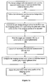
- Fig. 1a wherein an overview of an imaging system color profile neutral gray adjustment method of one embodiment of the present invention, is illustrated.
- the embodiment assumes that the imaging system to have its neutral gray outputs calibrated employs a color profile.
- the color profile includes an adjustable print table having mappings that map colors from a device-independent profile connection space (PCS) to the imaging system's color space for printing.
- PCS device-independent profile connection space
- the print tables may be tags, such as BtoAn tags in printer ICC profiles, where n is 0, 1, or 2, denoting a perceptual rendering intent.
- a print table may be organized in the form of a 3-D lookup table (LUT). Furthermore, it may include a set of 1-D tables in front of the 3-D LUT to adjust each of the PCS channels individually and a set of 1-D tables followed the 3-D LUT to adjust each of the imaging system channels.
- the embodiment adjusts the neutral nodes in the print table of the color profile, based on measurements of a printed target, printed using color values mapped in accordance with the print table.
- a target with near-neutral color patches surrounding neutral gray in various lightness levels from white to black, block 102 is first designed for printing and measurement.
- Fig. 2a illustrates one such example target defined in the context of an example PCS, the CIE L*a*b* color space.
- the target includes multiple near-neutral color patches surrounding the neutral area at different lightness levels.
- the near-neutral color patches comprise the area defined by ⁇ (L i , a i , ⁇ b i ), (L i , a i , b i ), (L i , -a i , b i ), (L i , -a i , -b i ) ⁇ .
- L*a*b* color space relative to media white the L i is from the media white (100) to black (0). In each L* level, there are nine near-neutral color patches.
- Pseudo codes to generate each of the color patches in L*a*b* color space relative to the media white are: where ⁇ a and ⁇ b are the intervals of a* coordinate and b* coordinate for the target design. There are total of n L* levels. In each L* level, there are three steps of a* and three steps of b*, which made a total of nine color patches in each L* level, or 9 by n color patches in the entire target.
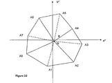
- Fig. 2b illustrates an example neutral aim expressed in the context of an example device-independent color space, the CIE L*a*b* space, relative to the media white (W).
- the point K in Fig. 2b denotes the black point.
- the neutral aim can be defined in two values, a* and b*, and then interpolate these two values to all L* levels. For example, if the color table to be modified has n neutral node points, n sets of L*a*b* color values for neutral aim points should be derived.
- the PCS may be of other device-independent luminance-chrominance color space models.
- the print table to be adjusted is applied to convert the pre-designed target defined in the PCS into the imaging system's color space, block 106 .
- the target is then printed using the imaging system, and measurements of the printed target are taken, employing e.g. a colorimeter or a spectrophotometer, block 108.
- Fig. 2c illustrates an example measurement of the earlier described target of Fig. 2b, in the context of the PCS.
- the dashed line in Fig. 2c represents the corresponding colors of the neutral points in the L* axis in Fig. 2b. It represents the neutral gray before applying the neutral calibration.
- the task of the neutral gray adjustment is to bring the neutral nodes to the aimed neutral axis as shown in Fig. 2b.
- the measured near-neutral patch is comprised of the area defined by the eight points A1-A8. See also Fig. 2d .
- the conversion operation may be avoided.
- the color values of the imaging system in each lightness level to yield the desire neutral gray are computed, based at least in part on the measurements of the printed target in the context of the PCS, blocks 112, to be described more fully below.
- the print table of the color profile of the imaging system may be adjusted accordingly, in view of the color values computed in block 112 , block 114.
- Fig. 1b illustrates the operations of block 112 in further details, in accordance with one embodiment.
- the operations start from the selection of a first neutral node (i.e. first lightness, or L*, level), block 124.
- a first neutral node i.e. first lightness, or L*, level
- the selection starts with a neutral node at either end of the lightness axis, however, in alternate embodiments, the selection may be arbitrary.
- the imaging system color values and their corresponding measured L*a*b* values surrounding of the corresponding L* level are retrieved, block 128.
- up to 9 set-pair (A1 to A8 and N in Fig. 2d) of these values are retrieved.
- Fig. 2d area analyses are performed to determine an area encompassing the desired neutral node of the lightness level (the location marked "X" for the example of Fig. 2d).
- the L*a*b* values and the associated imaging system color space values of A1 to A8 and N points are determined by the measurement of the color patches printed using the imaging system color space values converted from PCS values defined by the pre-designed target.
- the L*a*b* values of the location X (the aimed neutral gray) is defined by the neutral aim as shown in Fig. 2b.
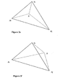
- the area analyses begin with constructing eight triangles, block 130. More specifically, the eight triangles are constructed by first dividing the area defined by the eight points A1-A8 into 4 quadrangles, A8A1A2N, A2A3A4N, A4A5A6N and A6A7A8N (see also Fig. 2d). Each of the 4 quadrangles is then further subdivided to provide 2 triangles, giving the total of 8 triangles.
- the 8 triangles are then exhaustively searched to determine the triangle containing the desired neutral color of a lightness level (point X for the example of Fig. 2d), block 132.
- the determination is made based on the principle that if the point X is within a triangle defined by three points AiAjN as the example of Fig. 2e, the area defined by AiAjN is equal to the sum of the areas defined by AiAjX, AjNX and NAiX respectively.
- point X is outside a triangle defined by the three points AiAjN as the example of Fig.
- the area defined by AiAjN is less than the sum of the areas defined by AiAjX, AjNX and NAiX respectively. Accordingly, the areas of the 3 triangles defined by AiAjNX, where (i j) equal to one of (8 1), (1 2), (2 3), (3 4), (4 5), (5 6), (6 7) and (7 8), are computed and compared to the area of AiAjN until the triangle containing the aimed neutral gray is found..
- the corresponding imaging system color value set (the color values in the device color space) is computed by three-point interpolation, block 134.
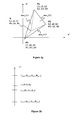
- Fig 2g graphically depicts the operation of block 134 for an embodiment where the color profile of the imaging system is a RGB profile.
- the triangle P1 P2P3 is equivalent to the triangle AiAjN in Fig. 2e. This is the triangle that contains the aimed neutral gray (Lx, ax, bx) in this L* level.
- the task in this step is to find (R0, G0, B0)
- the color values of each of the color channels, the Red (R), the Green (G) and the Blue (B) color channel, are calculated for the corresponding neutral gray output.
- the imaging device RGB color values are calculated by weighting the R, G and B color values based on the weights computed on the corresponding set of L*a*b* color space model values of the vertices of the triangle containing the neutral node of the lightness level in the PCS.
- the imaging system color space values (R x , G x , B x ) of the neutral aimed point X are calculated in accordance with the following formulas:
- Rx R 1 ⁇ area _023 + R 2 ⁇ area _013 + R 3 ⁇ area _012 area _123
- Gx G 1 ⁇ area _023+ G 2 ⁇ area _013 + G 3 ⁇ area _012 area _0123
- Bx B 1 ⁇ area _023 + B 2 ⁇ area _013 + B 3 ⁇ area _012 area _0123
- area_012, area_013 and area_023 are the areas occupied by triangles OP1P2, OP1P3 and OP2P3 in the 2-D a*b* plane; andarea_123 is the sum of area_012, area_013 and area_023.
- Each triangle area is computed using (L, a, b) coordinates of the three points of the triangle.
- (R x , G x , B x ) are the imaging system color space values to produce PCS values, (Lx, ax, bx).
- the intention is to have (Lx, ax, bx) equal to the aimed neutral gray (Li, ai, bi).
- L1, L2, and L3 of the three points in a triangle are not exactly equal to the value of L* level (Li)
- the Lx value of a lightness level is usually not exactly the same as Li.
- the RGB values of each point are adjusted to achieve an L* value of the corresponding node point, block 138.
- Fig. 2h shows how to perform this adjustment.
- a lightness level i its lower level is (i-1) and its upper level is (i+1).
- the L* value and corresponding (R, G, B) values of each level are obtained in the above process (blocks 124 to 136).
- L x,l is slightly off from Li.
- Li is in the range between L x,i and L x,l-1 , i and (i - 1) points should be applied for linear interpolation.
- the color profile of the imaging system may be other color profiles, e.g. a CMYK color profile.
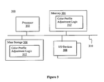
- FIG. 3 illustrates a computing device, suitable for use to practice at least some aspects of the method of Fig.1a-1b , in accordance with one embodiment.
- computing device 300 includes processor 302, memory 304, mass storage 306 and I/O devices 308 coupled to each other via bus 310.
- I/O devices 308 may include keyboards, cursor control devices, displays, communication interfaces, and so forth. Additionally, for some variants of embodiment, I/O devices 308 may comprise a spectrophotometer and/or a colorimeter.
- Memory 304 and mass storage 306 may be employed to store instructions and/or data, more specifically, a temporary and a permanent copy of color profile adjustment logic 312 implementing the method of Fig. 1a-1b.
- computing device 300 may be employed, e.g. by a manufacturer of an imaging system, or a user of an image system, to calibrate and generate a modified color profile for the imaging system, to facilitate more balanced and/or preferred imaging of neutral gray by the imaging system.
- computing device 300 may practice all or portion of the computing operations illustrated in Fig. 1a-1b .
- computing device 300 may receive (that is, provided with) the relevant measurements of the pre-designed targets, and performs the operations of blocks 110-112 in response.
- Computing device 300 may further cause the print table of the color profile of the imaging system to be adjusted accordingly, by providing the resulting color values to another computing device or to the imaging system, to in turn perform the adjustment operations of block 114.
- computing device 300 may be employed to perform only the computing operations of block 112 .
- computing device 300 may e.g. receive the converted measurements from another device, and performs the computing operations of blocks 112 in response.
- computing device 300 may further cause the color profile of the imaging system to be adjusted accordingly, by providing the resulting color values to another computing device or to the imaging system, to in turn perform the adjustment operation of block 114 .
- computing device 300 may perform also the measurement operations of block 108 as well as the adjustment operation of block 114.
- computing device 300 may perform all or some of the operations of blocks 108-114 of the color profile neutral gray calibration method of Fig. 1a-1b.
- processors 302, memory 304, mass storage 306, I/O devices 308 , and bus 310 represent a broad range of such elements.
- computing device 300 may be a server, a desktop computer, a computing tablet, a laptop computer, a palm sized personal assistant, a pocket PC, or other computing devices of the like.
- Imaging system 400 includes processor/controller 402 , memory 404 , imaging engine 406 and communication interface 408 coupled to each other via bus 410 .
- Imaging engine 406 comprises pens 412 for outputting various primary colorants.
- Memory 404 is employed to store instructions and/or data, more specifically, imaging control logic 426 , color profile 424 and color profile adjustment logic 422.
- Imaging control logic 426 is employed to control pens 412 to print images onto media.
- Color profile 424 is applied by imaging control logic 426 during imaging.
- Color profile adjustment logic 422 implements at least portions of the method of Fig. 1a-1b .
- imaging device 400 in addition to being used for imaging on media, may be employed, e.g. by its manufacturer or a user, to calibrate and adjust its color profile for outputting the desired neutral gray outputs.
- imaging device 400 may practice all or portion of the operations illustrated in Fig. 1a-1b .
- imaging device 400 may be employed to perform the operations of blocks 110-114.
- imaging device 400 receives (that is, provided with) the relevant measurements of the pre-designed target printing on the imaging device to be adjusted, and performs the operations of blocks 110-114 in response.
- imaging device 400 equipped with a colorimeter, a spectrophotometer or other measurement device of the like may be employed to perform also the operations of block 108.
- imaging device 400 may be employed to perform only the operations of blocks 112-114 .
- imaging device 400 receives the converted measurements, and performs the operations of blocks 112-114 in response.
- imaging device 400 may perform all or some of the operations of blocks 108-114 of the color profile neutral gray calibration method of Fig. 1a-1b.
- Imaging control logic 426 represents a broad range of such element, including but is not limited to imaging control logic found in many imaging systems available from Hewlett Packard Corp of Palo Alto, CA. In particular, imaging control logic 426 may be employed to image pixels of images onto media employing one or more colorants. Imaging control logic 426 accesses color profile 424 as adjusted by color profile adjustment logic 422 , and images the pixels accordingly.
- processors 402 , memory 404 , imaging engine 406, communication interfaces 408, and bus 410 represent a broad range of such elements.
- imaging device 400 may be an inkjet printer or an electrophotographic printer.
- Figure 5 illustrates an article suitable for use to store executable instructions implementing at least portions of the method of Fig.1 a-1 b , in accordance with one embodiment.
- storage medium 502 includes color profile adjustment logic 504 comprising instructions that implement operations 110-114 of the method of Fig. 1a-1b .
- the stored instructions may be used to program an apparatus, such as computing device 300 and/or imaging system 400, to perform some or all of operations 110-114 of the method of Fig. 1a-1b, as earlier described.
- color profile adjustment logic 504 may implement merely only some of operations 110-114 of the method of Fig. 1 a-1b.
- storage medium 502 may be a diskette, a tape, a compact disk (CD), a digital versatile disk (DVD), a solid state storage device, or other electrical, magnetic and/or optical storage devices of the like.
Landscapes
- Engineering & Computer Science (AREA)
- Multimedia (AREA)
- Signal Processing (AREA)
- Color Image Communication Systems (AREA)
- Facsimile Image Signal Circuits (AREA)
- Image Processing (AREA)
Applications Claiming Priority (2)
| Application Number | Priority Date | Filing Date | Title |
|---|---|---|---|
| US10/723,232 US20050110798A1 (en) | 2003-11-26 | 2003-11-26 | Imaging system color profile neutral gray adjustment |
| US723232 | 2003-11-26 |
Publications (2)
| Publication Number | Publication Date |
|---|---|
| EP1536631A2 true EP1536631A2 (fr) | 2005-06-01 |
| EP1536631A3 EP1536631A3 (fr) | 2005-11-30 |
Family
ID=34465701
Family Applications (1)
| Application Number | Title | Priority Date | Filing Date |
|---|---|---|---|
| EP04014505A Withdrawn EP1536631A3 (fr) | 2003-11-26 | 2004-06-21 | Réglage de gris neutre dans un profil couleur d'un système d'image |
Country Status (2)
| Country | Link |
|---|---|
| US (1) | US20050110798A1 (fr) |
| EP (1) | EP1536631A3 (fr) |
Cited By (2)
| Publication number | Priority date | Publication date | Assignee | Title |
|---|---|---|---|---|
| WO2012160346A1 (fr) * | 2011-05-20 | 2012-11-29 | Bodoni Systems Ltd | Appariement de couleurs |
| DE102008031735B4 (de) * | 2007-07-10 | 2019-11-07 | Heidelberger Druckmaschinen Ag | Graubalancekorrektur eines Druckverfahrens |
Families Citing this family (4)
| Publication number | Priority date | Publication date | Assignee | Title |
|---|---|---|---|---|
| US9521298B2 (en) * | 2010-07-13 | 2016-12-13 | Red Hat, Inc. | Color management system |
| JP5887980B2 (ja) * | 2012-02-15 | 2016-03-16 | 株式会社リコー | カラーマネジメント・システム |
| CN111326099B (zh) * | 2018-12-14 | 2021-10-01 | 西安诺瓦星云科技股份有限公司 | 显示校正方法、装置及系统、存储介质以及显示系统 |
| JP2020170134A (ja) * | 2019-04-05 | 2020-10-15 | 日本放送協会 | 色域表示装置、色域形状測定装置およびそれらのプログラム |
Family Cites Families (6)
| Publication number | Priority date | Publication date | Assignee | Title |
|---|---|---|---|---|
| US5999703A (en) * | 1997-03-27 | 1999-12-07 | Eastman Kodak Company | Computer program product for modifying the black channel of an output device profile without altering its colorimetric accuracy |
| US7307752B1 (en) * | 2000-05-05 | 2007-12-11 | Xerox Corporation | On-line calibration system for a dynamically varying color marking device |
| US7190487B2 (en) * | 2001-09-25 | 2007-03-13 | Sharp Laboratories Of America, Inc. | Color conversion with hue straightening using multiple look-up tables and interpolation |
| JP4562162B2 (ja) * | 2001-09-27 | 2010-10-13 | キヤノン株式会社 | 色処理方法及び装置とコンピュータプログラム、及びルックアップテーブルの製造方法 |
| US7304766B2 (en) * | 2002-04-01 | 2007-12-04 | Hewlett-Packard Development Company, L.P. | Method and apparatus for data adjustment |
| US7319545B2 (en) * | 2002-12-17 | 2008-01-15 | Xerox Corporation | Method and apparatus for calibration of a color printer |
-
2003
- 2003-11-26 US US10/723,232 patent/US20050110798A1/en not_active Abandoned
-
2004
- 2004-06-21 EP EP04014505A patent/EP1536631A3/fr not_active Withdrawn
Cited By (2)
| Publication number | Priority date | Publication date | Assignee | Title |
|---|---|---|---|---|
| DE102008031735B4 (de) * | 2007-07-10 | 2019-11-07 | Heidelberger Druckmaschinen Ag | Graubalancekorrektur eines Druckverfahrens |
| WO2012160346A1 (fr) * | 2011-05-20 | 2012-11-29 | Bodoni Systems Ltd | Appariement de couleurs |
Also Published As
| Publication number | Publication date |
|---|---|
| EP1536631A3 (fr) | 2005-11-30 |
| US20050110798A1 (en) | 2005-05-26 |
Similar Documents
| Publication | Publication Date | Title |
|---|---|---|
| US7054035B2 (en) | Method and system for management of color through conversion between color spaces | |
| EP0891078B1 (fr) | Appareil et procédé de correction de couleurs pour un système d'image | |
| US6421142B1 (en) | Out-of-gamut color mapping strategy | |
| EP1500513A2 (fr) | Linearisation d'intensités de sortie de stylos | |
| US7239425B2 (en) | Color processing method and apparatus for generating a conversion condition for converting data in a device independent color space into data in a device dependent color space | |
| US7542167B2 (en) | Smoothing lattice positions | |
| US20090080041A1 (en) | Multiple dimensional color conversion to minimize interpolation error | |
| JP6888507B2 (ja) | プロファイル調整方法、プロファイル調整プログラム、プロファイル調整装置、及び、プロファイル調整システム | |
| JP6950513B2 (ja) | 色変換テーブル調整方法、色変換テーブル調整プログラム、色変換テーブル調整装置、及び、色変換テーブル調整システム | |
| US8427722B2 (en) | Color transform insensitive to process variability | |
| US7126718B1 (en) | Adjustment of color appearance models | |
| US6160644A (en) | Scanner calibration technique to overcome tone inversion | |
| KR100629516B1 (ko) | 색역 경계 검출장치 및 이를 이용하는 매핑 장치 그리고그 방법 | |
| US20030193677A1 (en) | Method and apparatus for data adjustment | |
| CN111866303B (zh) | 颜色转换信息生成方法、以及颜色转换信息生成装置 | |
| EP1536631A2 (fr) | Réglage de gris neutre dans un profil couleur d'un système d'image | |
| US20060250624A1 (en) | Colorant control values for color printing devices | |
| WO2006109859A1 (fr) | Procede et appareil de traitement de couleurs | |
| US8005299B2 (en) | Adjusting colorants specified in a digital image | |
| US20030176281A1 (en) | Choice of chromophores in two color imaging systems | |
| US8310716B2 (en) | Systems and methods for designing a set of black generation transfer curves | |
| US20100020340A1 (en) | Method and system for visual calibration of printers | |
| US7688470B2 (en) | System and method for color calibration incorporating gray-component replacement using black value and intermediate color variable input | |
| US20080144114A1 (en) | Method and system for dynamic printer profiling | |
| US8705115B1 (en) | Generation of inverse transfer function for image rendering device |
Legal Events
| Date | Code | Title | Description |
|---|---|---|---|
| PUAI | Public reference made under article 153(3) epc to a published international application that has entered the european phase |
Free format text: ORIGINAL CODE: 0009012 |
|
| AK | Designated contracting states |
Kind code of ref document: A2 Designated state(s): AT BE BG CH CY CZ DE DK EE ES FI FR GB GR HU IE IT LI LU MC NL PL PT RO SE SI SK TR |
|
| AX | Request for extension of the european patent |
Extension state: AL HR LT LV MK |
|
| PUAL | Search report despatched |
Free format text: ORIGINAL CODE: 0009013 |
|
| AK | Designated contracting states |
Kind code of ref document: A3 Designated state(s): AT BE BG CH CY CZ DE DK EE ES FI FR GB GR HU IE IT LI LU MC NL PL PT RO SE SI SK TR |
|
| AX | Request for extension of the european patent |
Extension state: AL HR LT LV MK |
|
| 17P | Request for examination filed |
Effective date: 20060601 |
|
| AKX | Designation fees paid |
Designated state(s): DE GB NL |
|
| 17Q | First examination report despatched |
Effective date: 20070706 |
|
| STAA | Information on the status of an ep patent application or granted ep patent |
Free format text: STATUS: THE APPLICATION IS DEEMED TO BE WITHDRAWN |
|
| 18D | Application deemed to be withdrawn |
Effective date: 20080117 |