EP1536371B1 - Verfahren, um Defekte von Druckelementen eines Druckers zu tarnen - Google Patents
Verfahren, um Defekte von Druckelementen eines Druckers zu tarnen Download PDFInfo
- Publication number
- EP1536371B1 EP1536371B1 EP04106008A EP04106008A EP1536371B1 EP 1536371 B1 EP1536371 B1 EP 1536371B1 EP 04106008 A EP04106008 A EP 04106008A EP 04106008 A EP04106008 A EP 04106008A EP 1536371 B1 EP1536371 B1 EP 1536371B1
- Authority
- EP
- European Patent Office
- Prior art keywords
- pixel
- pixels
- printed
- line
- printer
- Prior art date
- Legal status (The legal status is an assumption and is not a legal conclusion. Google has not performed a legal analysis and makes no representation as to the accuracy of the status listed.)
- Active
Links
Images


Classifications
-
- B—PERFORMING OPERATIONS; TRANSPORTING
- B41—PRINTING; LINING MACHINES; TYPEWRITERS; STAMPS
- B41J—TYPEWRITERS; SELECTIVE PRINTING MECHANISMS, i.e. MECHANISMS PRINTING OTHERWISE THAN FROM A FORME; CORRECTION OF TYPOGRAPHICAL ERRORS
- B41J2/00—Typewriters or selective printing mechanisms characterised by the printing or marking process for which they are designed
- B41J2/005—Typewriters or selective printing mechanisms characterised by the printing or marking process for which they are designed characterised by bringing liquid or particles selectively into contact with a printing material
- B41J2/01—Ink jet
- B41J2/21—Ink jet for multi-colour printing
- B41J2/2132—Print quality control characterised by dot disposition, e.g. for reducing white stripes or banding
- B41J2/2139—Compensation for malfunctioning nozzles creating dot place or dot size errors
Definitions
- the invention relates to a method of camouflaging defective print elements in a printer having a printhead with a plurality of print elements, wherein each pixel of the image is assigned to a print element with which it is to be printed, and image information of a pixel that is assigned to a defective print element is shifted to a nearby pixel position where it can be printed by a non-defective print element.
- the invention further relates to a printer and to a computer program implementing this method.
- the invention is applicable, for example, to an ink jet printer the printhead of which comprises a plurality of nozzles as print elements.
- the nozzles are arranged in a line that extends in parallel with a direction (subscanning direction) in which a recording medium, e.g. paper, is transported through the printer, and the printhead scans the paper in a direction (main scanning direction) perpendicular to the subscanning direction.
- a recording medium e.g. paper
- the single-pass mode In a single-pass mode, commonly a complete swath of the image is printed in a single pass of the printhead, and then the paper is transported by the width of the swath so as to print the next swath or in general the single-pass mode is a mode wherein a complete line is printed by only one nozzle.
- a nozzle of the printhead When a nozzle of the printhead is defective, e.g. has become clogged, the corresponding pixel line is missing in the printed image, so that image information is lost and the quality of the print is degraded.
- a printer may also be operated in a multi-pass mode, in which only part of the image information of a swath is printed in a first pass and the missing pixels are filled-in during one or more subsequent passes of the printhead. In this case, it is in some cases possible that a defective nozzle is backed-up by a non-defective nozzle, though mostly on the cost of productivity.
- US-A-6 215 557 discloses a method of the type indicated above, wherein, when a nozzle is defective, the print data are altered so as to bypass the faulty nozzle. This means that a pixel that would have but cannot be printed with the defective nozzle is substituted by printing an extra pixel in one of the neighbouring lines that are printed with non-defective nozzles, so that the average optical density of the image area is conserved and the defect resulting from the nozzle failure is camouflaged and becomes almost imperceptible.
- This method involves an algorithm that operates on a bitmap, which represents the print data, and shifts each pixel that cannot be printed to a neighbouring pixel position.
- EP-A-0 999 516 discloses a method for generating a print mask which determines a pattern in which the pixels will be printed.
- This document focuses on multi-pass printing, and the main purpose of the mask is to determine which pixels are to be printed in which pass.
- the image information to be printed is taken into account only indirectly in the form of constraints that determine the construction of the mask. For example, such a constraint may require that a yellow pixel and a cyan pixel directly adjacent thereto are not printed in the same pass of the printhead, in order to avoid colour bleeding.
- This document further suggests to construct the masks in such a way that defective nozzles are backed up by non-defective nozzles.
- EP-A-1 060 896 discloses a printer according to the preamble of claim 10, wherein a printhead controller selects different print strategies depending upon whether or not a defective print element has been determined.
- step (a) which requires substantial data processing capacity and processing time is performed "in advance", i.e. at a stage where the actual locations of the defective nozzles, as determined in the subsequent step (b) are not yet known. Then, what is left to be done when a defective print element has been identified in step (b), either manually or automatically, is to execute the print instructions that have already been encoded in the pixel matrix for the pixels in the neighbourhood of the pixel that cannot be printed. As a consequence, the printer itself is not required to have enhanced image processing capabilities nor to perform time-consuming processing steps in order to camouflage the effect of the defective nozzles.
- step (a) may be performed at a location remote from the printer and the result may be buffered, if necessary, while the printer is busy with another print job. This leads to a considerable increase in the productivity of the printer, especially in a multi-user scenario. Moreover, since the step (a) does not depend on the exact locations of the nozzle defects, it is possible to perform this step even before it is known to which printer the data will be sent, i.e. the print data obtained as a result of step (a) are portable among different printers.
- the hardware which is used for performing the step (a) and which may be installed in the printer itself or remote from the printer, will preferably be of a type that is suitable for high-speed image processing and may also be used for other complex image processing tasks such as halftoning, gamma correction, contrast enhancement, image segmentation and the like.
- the data processing involved in the step (a) can be performed at high speed.
- the plurality of predetermined pixel values of the multi-level pixel matrix comprise three values: an unconditional value "0" which stands, in any case, for a white pixel, a pixel value "2" which, in any case, stands for a black pixel, and a conditional pixel value "1", which stands for a black pixel, i.e. the print instruction "print”, if at least one of the neighbouring pixels corresponds to a defective print element, and which stands for a white pixel, i.e. the print instruction "don't print", otherwise.
- the pixel matrix may have a larger number of predetermined pixel values.
- the predetermined pixel values may comprise the unconditional pixel values "0", "2", and "4", for printing no dot, a small dot, and a large dot, respectively, and the conditional pixel values "1" and "3" for printing a small dot and a large dot, respectively, when one or more non-printable pixels are present in the neighbourhood.
- the print instructions encoded by the conditional pixel values may also be of a more complex nature and may, for example, specify that a simple error diffusion step (which does not require much processing capacity and time) shall be performed for the pixels adjacent to non-printable pixels. Then, the pixel value assigned to a specific pixel will indicate the weight that is given to this pixel in the error diffusion process.
- the printer operates in a single-pass mode, then a defect of a single nozzle will lead to a complete line of non-printable pixels.
- the conditional pixel values will be interpreted as "don't print” for all the pixels except those in the line or lines immediately above and/or below the non-printable line.
- the original image data to be printed are binary data, where each pixel has either the value "0" or "1”
- the multi-level pixel matrix may be constructed as follows. For every pixel having the value "1" in the original print data, the pixel value is changed to an unconditional value, e.g. "2", which stands for a pixel to be printed, and the pixel or pixels immediately above and/or below this pixel obtain a conditional pixel value (e.g. "1").
- each pixel line is printed with two different nozzles, and if one of these nozzles is defective, only every second pixel in the line will be missing.
- any given non-printable pixel will generally be surrounded by four printable pixels, i.e. the pixels above and below and also its left and right neighbours.
- the multi-level pixel matrix may be constructed as follows. Every pixel with the value "1" in the original print data is changed to the unconditional value which stands for a pixel to be printed, and the pixel value(s) of one or more of the neighbouring pixels will be incremented by one, provided that its original value was "0". If, for example, four neighbouring pixels are incremented, i.e.
- conditional values of a pixel may be "1", "2", or "3", depending on how many original "1" pixels are found in its surroundings.
- the height of the unconditional pixel value will determine the likelihood and/or the intensity (e.g. dot size) with which a pixel will be printed.
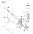
- an ink jet printer comprises a platen 10 which serves for transporting a recording paper 12 in a subscanning direction (arrow A) past a printhead unit 14.
- the printhead unit 14 is mounted on a carriage 16 that is guided on guide rails 18 and is movable back and forth in a main scanning direction (arrow B) relative to the recording paper 12.
- the printhead unit 14 comprises four printheads 20, one for each of the basic colours cyan, magenta, yellow and black.
- Each printhead has a linear array of nozzles 22 extending in the subscanning direction.
- the nozzles 22 of the printheads 20 can be energised individually to eject ink droplets onto the recording paper 12, thereby to print a pixel on the paper.
- a swath of an image can be printed.
- the number of pixel lines of the swath corresponds to the number of nozzles 22 of each printhead.
- the paper 12 is advanced by the width of the swath, so that the next swath can be printed.
- the printheads 20 are controlled by a printhead controller 24 which receives print data in the form of a multi-level pixel matrix from an image processor 26 that is capable of high speed image processing.
- the image processor 26 may be incorporated in the printer or in a remote device, e. g. a print driver in a host computer.
- the printhead controller 24 and the image processor 26 process the print data in a manner that will be described in detail hereinbelow. The discussion will be focused on printing in black colour, but is equivalently valid for printing in the other colours.
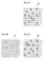
- Figure 2A shows an array of 8x8 pixels 28 of a binary image 30 that is to be printed with the printer shown in figure 1.
- the print data representing the binary image 30 are created in or supplied to the image processor 26.
- the image 30 comprises a thin horizontal line 32 having only a width of one pixel, and a thin diagonal line 34.
- the pixels having a binary value "1", i.e. the pixels to be printed in black, are indicated by hatching.
- Figure 2B shows a printed image as it would be obtained by printing the binary image 30 when one of the nozzles 22 of the printhead 20 fails.
- pixel lines are indicated by their line index ranging from i-4 to i+3, and pixel columns are indicated by their column index ranging from j-4 to j+3.
- Individual pixels will be referred to by their coordinates, i.e. a pair of a line index and a column index such as (i, j).
- Figure 2C shows a multi-level pixel matrix 38, a three-level pixel matrix in this case, which is obtained by applying an image processing routine to the binary image 30 by means of the image processor 26.
- each pixel may have one of three pixel values: "0", "1” and "2".
- the image data representing the pixel matrix 38 are transmitted to the printhead controller 24 and will be interpreted by the printhead controller as follows.
- a pixel value "0" means that the pixel shall not be printed, i.e. shall be left blank or white.
- a pixel value of "2" means that the pixel shall be printed (black).
- a pixel value of "1" means that the pixel shall be treated as a "0"-pixel and shall not be printed, unless a nozzle failure occurs for one of the pixel lines immediately above and below this pixel. In the latter case, the pixel shall be treated as a "2" pixel and shall be printed.
- the value "1" of the pixel (i-1, j-1) means that this pixel shall only be printed if either the nozzle needed for printing the line i or the nozzle needed for printing line i-2 is defective.
- the printer may be arranged for automatically detecting nozzle failures, as is generally known in the art.
- the information needed for determining whether or not a nozzle is defective will be available in the printhead controller 24 which interprets the pixel matrix 38.
- nozzle failures may of course be detected manually by an operator who will to this end analyse a specific test image and will enter an information identifying the defective nozzles into the printhead controller 24 by suitable input means.
- the pixel matrix 38 is derived from the binary image 30 by means of the following algorithm. Every "1" (black pixel) in the binary image 30 is translated into a "2" in the pixel matrix 38. For example, this leads to the pixel value "2" for the pixel (i+3, j-4) in figure 2C. In addition, the pixel immediately below this "2"-pixel is changed from "0" to "1". This is the case, for example, for the pixel (i+2, j-4). If, however, the pixel immediately below the "2"-pixel was a black pixel already, it will be changed to "2" as every other other black pixel. An example for this is the pixel (i-1, j).
- a printed image 40 obtained as a result of this image processing step and its interpretation in the printhead controller 24 is shown in figure 2D. It can be seen that, thanks to the algorithm described above, the image information of the black line 32 is not lost, but is replaced by a black line 32' immediately below the defective nozzle. In other words, the line 32 is shifted by one pixel, and this shift will be hardly perceptible by the human eye. In all the pixel lines that are not directly adjacent to the line i of the defective nozzle, (lines i-4 to i-2, i+2 and i+3) the original image information is preserved without any changes. In line i+1, an additional black pixel (i+1, j-3) occurs close to the position, where the diagonal line 34 crosses the horizontal line 32'.
- This additional black pixel stems from the "2"-pixel (i+2, j-3) in figure 2C, which pixel has caused an "1" occurring immediately therebelow.
- the main purpose of this "1" was to replace the "2"-pixel in line i+2 in case that the nozzle for line i+2 should fail.
- the printhead controller 24 of this embodiment does not distinguish whether a line is located below or above a defective line, the pixel (i+1, j-3) will be printed in black, even though there is no defect in the line i+2. This behaviour leads to a slight overcompensation of the nozzle defect, but is highly welcome here, because it camouflages, to some extent, the gap occurring in the diagonal line 34 in pixel line i.
- Another possible strategy would be to insert a "1" pixel alternatingly above and below each "2" pixel. This strategy would be suitable for example for images consisting of extended grey areas, but would be unfavourable in case of horizontal high-contrast boundaries, because the boundary would become rugged if a nozzle failure occurs right at the boundary.
- image processing routines which comprise, for example, image segmentation in order to classify different types of image elements, such as thin lines, high-contrast boundaries, grey-shade areas and the like.
- the aim of the image processing algorithm will be to obtain a printed image 40 that resembles as far as possible the original image 30, regardless of the position where the nozzle failure occurs.
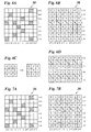
- Figures 3A-C illustrate an embodiment, in which "1 "-pixels are added alternatingly above and below each "2" pixel.
- this embodiment is particularly suitable for a binary image 30, as shown in figure 3A, in which the black pixels appear to be scattered randomly over the image area.
- the corresponding pixel matrix 38 shown in figure 3B is constructed almost in the same way as the pixel matrix in figure 2B, with the only difference that, for the "2"-pixels, the corresponding "1" pixels are inserted alternatingly above and below the "2" pixel, as is symbolised by arrows in figure 3B.
- the "1"-pixel that would be created by the "2" pixel i+3, j+2) is not visible here, because it is outside of the image area.
- the printhead controller 24 interprets the pixel matrix 38 in the same way as in figures 2B,C.
- the resulting printed image 40 is hardly distinguishable from the original image 30, in spite of the nozzle failure in line i.
- the sum of black pixels in the lines i-1, i, and i+1 in figure 3C is slightly larger than in figure 3A, because "1"-pixels are also created by black pixels in the lines i-2 and i+2. If this effect is not desirable, for example in case of image areas with a relatively high average density, the image processing algorithm may be modified by suppressing some of the additional "1 "-pixels.
- the first "2"-pixel may create a “1” pixel above
- the second "2"-pixel creates a "1 "-pixel below
- the third "2"-pixel does not create any "1” pixel at all, and then the sequence will be repeated.
- FIG. 4A shows the lines i-2 to i+1 form an extended dark area with an average density of 50%.
- An isolated black pixel is present at (i-4, j).
- Figure 4B shows the corresponding printed image 36 that would be obtained if the nozzle failure in line i were not camouflaged.
- Figure 4C shows a corresponding multi-level pixel matrix 38 which in this case is a four-level matrix.
- the pixel value "3" means that a back pixel shall be printed unconditionally.
- the pixel value "0" stands again for pixels that are to be left blank, unconditionally.
- the pixel value "1" means that the pixel shall be printed in black on condition that a nozzle failure occurs in the line immediately below. Conversely, the pixel value "2" means that the pixel shall be printed in black on condition that a nozzle failure occures in the line immediately above.
- every black pixel in the original image 30 is changed to "3".
- the algorithm for assigning the conditional pixel values "1" and "2" is more complex in this case. Since the lines i+2 and i+3 include no black pixels, the line i+1 forms the upper boundary of a grey area. for thos reason, no "1 "-pixels are provided in line i+2. Thus, even when a nozzle failure would occur for the line i+1, this would not be compensated by any black pixels in line i+2. Nor would there be any additional black pixels in line i for compensating the nozzle failure, because the line i does not contain any "2"-pixels. Thus, when the nozzle for line i+1 fails, this line is simply left white without any compensation, with the result that the boundary between the dark and the white area is shifted by one pixel. This has the advantage that a smooth appearance of the boundary is preserved.
- the line i-2 forms the lower boundary of the grey area, and the smooth appearance of this boundary should be preserved. For this reason, similarly as for line i+1, there are no "2"-pixels in line i-3, and the pixels above the "3"-pixels at j-3 and j+1 are left at "0". Thus, if a nozzle failure should occur in the boundary line i-2, this failure would not be compensated at all.
- a more elaborated embodiment may provide that all black pixels in the original image 30 obtain the pixel value "4" instead of "3". Then, the pixel value "3" would indicate that a black pixel shall be printed on condition that a nozzle failure occurs in anyone of the adjacent upper and lower lines. Thus, if a "2" is required because of a black pixel in the upper line, and at the same time a "1” is required because of a black pixel in the lower line, then the values "1" and "2" are added to give the conditional pixel value "3".
- Figures 5A-C illustrate a modified embodiment which requires slightly more processing capability of the printhead controller 24.
- the image processor 26 constructs the pixel matrix 38 shown in figure 5B on the basis of the binary image 30 shown in figure 5A.
- the pixel matrix is again a three-level matrix, wherein the pixel value "2" is assigned to each of the black pixels in the image 30.
- a "1" is inserted in the line immediately above and another "1" in the line immediately below.
- the printhead controller 24 interprets the pixel value "2" as black and the pixel values "0" and "1" as white.
- a special treatment is applied to the lines i-1 and i+1.
- this special treatment consists of a simple one-dimensional error diffusion process with threshold 2. Starting with the first pixel (j-4) in line i+1, the pixel value "1" is below the threshold 2, so that the pixel is left white in figure 5C. The rest (1) is added to the pixel value of the next pixel (i+1, j-3).
- the embodiment described here has the advantage that the image information which has been spread from line i to the adjacent lines will not be lost, even when the position right above or below is already occupied by a black pixel. Thanks to the error diffusion, the image information will instead be propagated to the next empty pixel position.
- This embodiment can of course be modified in various ways. For example, it is possible to adopt more complex error diffusion schemes, including also 2-dimensional error diffusion (where part of the error is diffused, for example, from line i+1 to i-1).
- the threshold employed in the error diffusion process does not have to be an integral number. It would be possible for example to adopt a threshold of 1.8 or 2.2, resulting in a slight tendency towards overcompensation and undercompensation, respectively, of the nozzle failure.
- the error diffusion process may also be replaced by other suitable algorithms.
- the pixel values in lines i-1 and i+1 may each be compared to a respective threshold which varies randomly between 0 and 2, and a black pixel may be printed, when the threshold is exceeded.
- the result will be that a "1 "-pixel will be printed as a black pixel with a probability of 50%. Since every "2" pixel in line i generates two "1" pixels, one in line i-1 and one in line i+1, the average density will be preserved if each of these "1" pixels is printed with a probability of 50%.
- the embodiments described above are adapted to a single-pass print mode, in which a nozzle failure leads to the loss of a complete pixel line
- the invention is also applicable to multi-pass printing, where a plurality of nozzles contribute to a given pixel line, so that a failue of a single nozzle leads only to a loss of a fraction of the pixels of the line. If no substantial post-processing shall be performed in the printhead controller 24, the methods for multi-pass printing will be analogous to what has been described in conjunction with figures 2 to 4, possibly with the additional feature that, in the construction of the pixel matrix, a distinction is made as to which of the nozzles that contribute to the same line is defective.
- Figures 6 and 7 illustrate two embodiments that are specifically adapted to two-pass printing and involve some post-processing such as error diffusion in the printhead controller 24.
- the binary image 30 shown in figure 6A is processed in the image processor 26 so as to construct the pixel matrix 38 shown in figure 6B.
- This pixel matrix is a 8-level matrix having the pixel values ranging from "0" to "8".
- the construction scheme for the pixel matrix 38 is symbolically shown in figure 6C: Every black pixel "1" of the original image 30 is changed to a "4", and the pixel values of the upper, lower, left and right neighbours of this pixel are increased by 1. In case of interference, the increments of the pixel value are summed.
- the pixel value "2" of the pixel (i, j-3) in figure 6B is obtained by adding a "1” from pixel (i, j-4) and another "1” from pixel (i, j-2).
- the sum may reach the maximum value of "8" (a "4" for the central pixel plus four "1”s from four black neighbours).
- the pixel matrix 38 is interpreted and post-processed in the printhead controller 24. Again, it shall be assumed that a nozzle failure occurs in line i. However, in the two-pass mode, this will have the effect that every second pixel in line i can still be printed. The remaining pixels that cannot be printed, have been crossed out in figure 6B. By way of example, it is assumed that these are the pixels at positions j-4, j-2, j and j+2. Since three of these pixels happen to be black pixels in figure 6A, the loss of image information that needs to be compensated amounts to 3 pixel.
- the pixels in the lines i-1, i and i+1 are subjected to error diffusion with threshold 5.
- the non-printable pixels in line i are skipped.
- the result is 18.
- the three missing pixels in line i will be compensated by three extra pixels in the neighbourhood, and the rest of 3 will be discarded.
- the reason for selecting the threshold value 5 in this embodiment will be explained in conjunction with figure 6D.
- the upper block in figure 6D shows the lines i-1, i and i+1 of an original binary image, wherein lines i-1 and i+1 are white, and i is a continous black line, black pixels being indicated by the pixel value "1".
- the total number of black pixels in lines i-1 to i+1 is 8.
- the error diffusion scheme and the threshold value may be varied as desired.
- the embodiment shown in figure 6 may in some rare cases lead to artefacts in the form of extra pixels that are added to the original image 30, even when no nozzle failure occurs.
- the pixel (i, j) is white in the original image 30, but the four adjacent pixels (i+1, j), (i, j-1), (i, j+1) and (i-1, j) are black. Then, the increments from the surrounding pixels will sum up to a pixel value of "4" for the pixel (i, j), and this pixel value would unconditionally be interpreted as black, so that the white pixel would be turned into a black one, even when no nozzle failure occurs.
- the embodiment may be modified as follows: Instead of encoding an original black pixel by the pixel value "4", it is encoded by the pixel value "5". This pixel value or a higher pixel value can only be reached when the original pixel was black already. In the printhead controller 24, only pixel values of "5" or higher will now be interpreted unconditionally as black, and the pixel value "4" is interpreted as white, where no error diffusion is performed. In the error diffusion process, the pixel value of "5" will only be counted as 4, a pixel value of "6” will be counted as 5, and so on up to the highest possible pixel value of "9", which will be counted as 8.
- the figures 7A and B illustrate another embodiment, which is also adapted to a two-pass print mode.
- the binary image 30 shown in figure 7A is the same as in figure 6A.
- the black pixels of the binary image are in this case translated only into the pixel value "2”, and an increment of "1" is added only to one of its four neighbours.
- the selection of the neighbour, to which the increment of "1" is added rotates counter-clockwise, when the "2"-pixels are gone through line by line. This counter-clockwise rotation is indicated by arrows in figur 7B.
- an increment of "1" is added only to its right neighbour (i+3, j+3).
- the incremented pixel values may range from “0" to "4", and the values "2", "3” and "4" will be interpreted as black pixels, where no error diffusion is performed.
- the pixels in the line i of the nozzle failure and the lines immediately above and below are subjected to error diffusion with a suitable threshold value.
- a consideration similar to the one explained in conjunction with figure 6D shows that a threshold value of 3 would be suitable in this case.
- the non-printable pixels would be (i, j-4), (i, j-2), (i, j) and (i, j+2).
Landscapes
- Engineering & Computer Science (AREA)
- Quality & Reliability (AREA)
- Ink Jet (AREA)
Claims (12)
- Verfahren zum Verschleiern von schadhaften Druckelementen (22) in einem Drucker, der einen Druckkopf (20) mit mehreren Druckelementen (22) aufweist, bei dem jedes Pixel (28) des Bildes einem Druckelement (22) zugewiesen wird, mit dem es gedruckt werden soll, und Bildinformation eines Pixels, das einem schadhaften Druckelement zugewiesen ist, auf eine nahegelegene Pixelposition verschoben wird, wo sie mit einem nicht schadhaften Druckelement gedruckt werden kann, gekennzeichnet durch die Schritte:a) Codieren der zu druckenden Bildinformation (30) als eine mehrwertige Pixelmatrix (38), bei der jedem Pixel einer von mehreren vorbestimmten Pixelwerten zugewiesen wird und wenigstens einer dieser vorbestimmten Pixelwerte ein konditionierter Pixelwert ist, der einen Druckbefehl codiert, der davon abhängig ist, ob ein benachbartes Pixel gedruckt werden kann oder wegen eines schadhaften Druckelements nicht gedruckt werden kann,b) Bestimmen von schadhaften Druckelementen (22) des Druckers undc) Ausführen des Druckbefehls.
- Verfahren nach Anspruch 1, bei dem in Schritt (c) der konditionierte Pixelwert als ein zu druckendes Pixel interpretiert wird, wenn wenigstens eines der benachbarten Pixel einem schadhaften Druckelement entspricht, und andernfalls als ein nicht zu druckendes Pixel interpretiert wird.
- Verfahren nach Anspruch 1, bei dem der Schritt (c) einen Nachverarbeitungsschritt einschließt, in dem für jedes Pixel, dem ein konditionierter Pixelwert zugewiesen ist, ein Pixel mit einer Wahrscheinlichkeit, die durch den genannten konditionierten Pixelwert bestimmt ist, in derselben Pixelposition oder einer benachbarten Pixelposition gedruckt wird.
- Verfahren nach Anspruch 3, bei dem der Nachverarbeitungsschritt einen Fehlerdiffusionsschritt einschließt.
- Verfahren nach Anspruch 3 oder 4, bei dem der Nachverarbeitungsschritt nur für Pixel in der Nachbarschaft eines Pixels ausgeführt wird, das einem schadhaften Druckelement entspricht.
- Verfahren nach Anspruch 5, bei dem, für einen multi-pass Druckmodus, die Nachverarbeitung beschränkt ist auf die Pixelzeile (i), die einem schadhaften Druckelement entspricht, und die Pixelzeilen (i-1, i+1) direkt über und unter dieser Zeile.
- Verfahren nach einem der vorstehenden Ansprüche, bei dem der Schritt(a) einen Schritt der Konstruktion der genannten mehrwertigen Pixelmatrix einschließt, bei dem jedem Pixel, das gemäß der ursprünglichen Bildinformation gedruckt werden soll, ein hoher unkonditionierter Pixelwert zugewiesen wird und die Pixelwerte von anderen Pixeln, die diesen Pixeln direkt benachbart sind, erhöht werden.
- Verfahren nach Anspruch 7, bei dem für jedes Pixel, dem der genannte hohe unkonditionierte Pixelwert zugewiesen worden ist, die Pixelwerte der Nachbarn um gleiche Inkremente erhöht werden.
- Verfahren nach Anspruch 7, bei dem für eine Abfolge von Pixeln, denen der genannte hohe unkonditionierte Pixelwert zugewiesen worden ist, ein Inkrement nur zu dem Pixelwert eines ausgewählten Pixels unter den Nachbarn jedes Pixels additiert wird und die Auswahl des Nachbarn, für den der Pixelwert erhöht wird, fortlaufend variiert wird.
- Drucker mit einem Druckkopf (20) mit mehreren Druckelementen (22), unter einer Druckkopf-Steuereinheit (24), die dazu eingerichtet ist, schadhafte Druckelemente (22) des Druckers zu erkennen, dadurch gekennzeichnet, daß die Druckkopf-Steuereinheit (24) dazu eingerichtet ist, eine mehrwertige Pixelmatrix (38) zu interpretieren, die in einem Schritt (a) nach Anspruch 1 spezifiziert worden ist, und einen in dieser Pixelmatrix codierten Druckbefehl auszuführen, wenn der Drucker bei der Ausführung des Verfahrens nach einem der Ansprüche 1 bis 9 eingesetzt wird.
- Drucker nach Anspruch 10, mit einem Bildprozessor (26), der dazu eingerichtet ist, den Schritt (a) dieses Verfahrens auszuführen.
- Computerprogramm mit Computerprogrammcode, der einen Drucker das Verfahren nach einem der Ansprüche 1 bis 9 ausführen läßt.
Priority Applications (1)
| Application Number | Priority Date | Filing Date | Title |
|---|---|---|---|
| EP04106008A EP1536371B1 (de) | 2003-11-27 | 2004-11-23 | Verfahren, um Defekte von Druckelementen eines Druckers zu tarnen |
Applications Claiming Priority (3)
| Application Number | Priority Date | Filing Date | Title |
|---|---|---|---|
| EP03078754A EP1536370A1 (de) | 2003-11-27 | 2003-11-27 | Verfahren um Defekte von Druckelementen eines Druckers zu tarnen |
| EP03078754 | 2003-11-27 | ||
| EP04106008A EP1536371B1 (de) | 2003-11-27 | 2004-11-23 | Verfahren, um Defekte von Druckelementen eines Druckers zu tarnen |
Publications (2)
| Publication Number | Publication Date |
|---|---|
| EP1536371A1 EP1536371A1 (de) | 2005-06-01 |
| EP1536371B1 true EP1536371B1 (de) | 2007-05-02 |
Family
ID=34466342
Family Applications (1)
| Application Number | Title | Priority Date | Filing Date |
|---|---|---|---|
| EP04106008A Active EP1536371B1 (de) | 2003-11-27 | 2004-11-23 | Verfahren, um Defekte von Druckelementen eines Druckers zu tarnen |
Country Status (1)
| Country | Link |
|---|---|
| EP (1) | EP1536371B1 (de) |
Families Citing this family (3)
| Publication number | Priority date | Publication date | Assignee | Title |
|---|---|---|---|---|
| JP2007083704A (ja) * | 2005-08-25 | 2007-04-05 | Seiko Epson Corp | 印刷装置、印刷プログラム、印刷方法および画像処理装置、画像処理プログラム、画像処理方法、並びに前記プログラムを記録した記録媒体 |
| WO2012034841A1 (en) | 2010-09-14 | 2012-03-22 | Oce-Technologies B.V. | Method of camouflaging artefacts in high coverage areas in images to be printed |
| DE102015220716A1 (de) | 2014-11-13 | 2016-05-19 | Heidelberger Druckmaschinen Ag | Verfahren zur Kompensation ausgefallener Druckdüsen in Inkjet-Drucksystemen |
Family Cites Families (4)
| Publication number | Priority date | Publication date | Assignee | Title |
|---|---|---|---|---|
| IL117278A (en) * | 1996-02-27 | 2000-02-17 | Idanit Tech Ltd | Method for operating an ink jet printer |
| NL1012376C2 (nl) * | 1999-06-17 | 2000-12-19 | Ocu Technologies B V | Werkwijze voor het bedrukken van een substraat en een drukinrichting geschikt om deze werkwijze toe te passen. |
| US6508531B1 (en) * | 2002-01-14 | 2003-01-21 | Aprion Digital Ltd. | Method for reducing variations in print density |
| JP4164305B2 (ja) * | 2002-07-24 | 2008-10-15 | キヤノン株式会社 | インクジェット記録方法およびインクジェット記録装置 |
-
2004
- 2004-11-23 EP EP04106008A patent/EP1536371B1/de active Active
Non-Patent Citations (1)
| Title |
|---|
| None * |
Also Published As
| Publication number | Publication date |
|---|---|
| EP1536371A1 (de) | 2005-06-01 |
Similar Documents
| Publication | Publication Date | Title |
|---|---|---|
| EP1536370A1 (de) | Verfahren um Defekte von Druckelementen eines Druckers zu tarnen | |
| US7903290B2 (en) | Printing method with camouflage of defective print elements | |
| EP1529644B1 (de) | Verfahren zur Maskierung von ausgefallenen Druckelementen in einem Drucker | |
| US8477361B2 (en) | Image data generating apparatus and image data generating method for generating image data when an image is printed in a divided manner | |
| JP4280732B2 (ja) | 記録装置、データ処理装置、マスク製造方法およびマスクパターン | |
| US8018621B2 (en) | Data generation and printing with binarization pattern selected as function of pixel number corresponding to conveying amount of print medium | |
| JP3829508B2 (ja) | 画像処理装置、画像処理方法および印刷装置 | |
| US7710608B2 (en) | Printing apparatus, printing apparatus control program, printing apparatus control method, printing data creating apparatus, printing data creating program and printing data creating method | |
| JP4564979B2 (ja) | データ処理装置、記録装置およびマスクパターンの製造方法 | |
| JP2011042166A (ja) | 画像データ生成装置、記録装置および画像データ生成方法 | |
| EP0944024B1 (de) | Verringerung von periodischen Artefakten in inkrementellem Druck | |
| JP2009083503A (ja) | データ処理方法、データ処理装置、マスク製造方法およびマスクパターン | |
| US8491078B2 (en) | Printing apparatus and printing method | |
| JP2000135801A (ja) | 印刷装置 | |
| EP1536371B1 (de) | Verfahren, um Defekte von Druckelementen eines Druckers zu tarnen | |
| EP1634709A1 (de) | Druckverfahren mit Verschleierung von defekten Druckelementen | |
| EP1593516B1 (de) | Druckverfahren mit Tarnung von defekten Druckelementen | |
| JP2015143011A (ja) | インクジェット記録装置および画像処理装置 | |
| US11956403B1 (en) | Edge enhancement with compensation mechanism | |
| US11962737B1 (en) | Edge enhancement with compensation mechanism | |
| JP2022156781A (ja) | 画像処理装置、画像処理方法及びプログラム | |
| JP2021146692A (ja) | 液体吐出装置、画像処理方法及びプログラム | |
| JP2010018006A (ja) | 画像形成装置及びその制御方法、プログラム | |
| JP2018030244A (ja) | 記録装置および記録方法 | |
| JP2005137019A (ja) | 画像処理装置、画像処理方法および印刷装置 |
Legal Events
| Date | Code | Title | Description |
|---|---|---|---|
| PUAI | Public reference made under article 153(3) epc to a published international application that has entered the european phase |
Free format text: ORIGINAL CODE: 0009012 |
|
| AK | Designated contracting states |
Kind code of ref document: A1 Designated state(s): AT BE BG CH CY CZ DE DK EE ES FI FR GB GR HU IE IS IT LI LU MC NL PL PT RO SE SI SK TR |
|
| AX | Request for extension of the european patent |
Extension state: AL HR LT LV MK YU |
|
| 17P | Request for examination filed |
Effective date: 20051201 |
|
| AKX | Designation fees paid |
Designated state(s): AT BE BG CH CY CZ DE DK EE ES FI FR GB GR HU IE IS IT LI LU MC NL PL PT RO SE SI SK TR |
|
| GRAP | Despatch of communication of intention to grant a patent |
Free format text: ORIGINAL CODE: EPIDOSNIGR1 |
|
| GRAS | Grant fee paid |
Free format text: ORIGINAL CODE: EPIDOSNIGR3 |
|
| GRAA | (expected) grant |
Free format text: ORIGINAL CODE: 0009210 |
|
| AK | Designated contracting states |
Kind code of ref document: B1 Designated state(s): AT BE BG CH CY CZ DE DK EE ES FI FR GB GR HU IE IS IT LI LU MC NL PL PT RO SE SI SK TR |
|
| PG25 | Lapsed in a contracting state [announced via postgrant information from national office to epo] |
Ref country code: CH Free format text: LAPSE BECAUSE OF FAILURE TO SUBMIT A TRANSLATION OF THE DESCRIPTION OR TO PAY THE FEE WITHIN THE PRESCRIBED TIME-LIMIT Effective date: 20070502 Ref country code: LI Free format text: LAPSE BECAUSE OF FAILURE TO SUBMIT A TRANSLATION OF THE DESCRIPTION OR TO PAY THE FEE WITHIN THE PRESCRIBED TIME-LIMIT Effective date: 20070502 Ref country code: FI Free format text: LAPSE BECAUSE OF FAILURE TO SUBMIT A TRANSLATION OF THE DESCRIPTION OR TO PAY THE FEE WITHIN THE PRESCRIBED TIME-LIMIT Effective date: 20070502 |
|
| REG | Reference to a national code |
Ref country code: GB Ref legal event code: FG4D |
|
| REG | Reference to a national code |
Ref country code: CH Ref legal event code: EP |
|
| REG | Reference to a national code |
Ref country code: IE Ref legal event code: FG4D |
|
| REF | Corresponds to: |
Ref document number: 602004006216 Country of ref document: DE Date of ref document: 20070614 Kind code of ref document: P |
|
| PG25 | Lapsed in a contracting state [announced via postgrant information from national office to epo] |
Ref country code: SE Free format text: LAPSE BECAUSE OF FAILURE TO SUBMIT A TRANSLATION OF THE DESCRIPTION OR TO PAY THE FEE WITHIN THE PRESCRIBED TIME-LIMIT Effective date: 20070802 |
|
| PG25 | Lapsed in a contracting state [announced via postgrant information from national office to epo] |
Ref country code: ES Free format text: LAPSE BECAUSE OF FAILURE TO SUBMIT A TRANSLATION OF THE DESCRIPTION OR TO PAY THE FEE WITHIN THE PRESCRIBED TIME-LIMIT Effective date: 20070813 |
|
| PG25 | Lapsed in a contracting state [announced via postgrant information from national office to epo] |
Ref country code: IS Free format text: LAPSE BECAUSE OF FAILURE TO SUBMIT A TRANSLATION OF THE DESCRIPTION OR TO PAY THE FEE WITHIN THE PRESCRIBED TIME-LIMIT Effective date: 20070902 |
|
| REG | Reference to a national code |
Ref country code: CH Ref legal event code: PL |
|
| PG25 | Lapsed in a contracting state [announced via postgrant information from national office to epo] |
Ref country code: AT Free format text: LAPSE BECAUSE OF FAILURE TO SUBMIT A TRANSLATION OF THE DESCRIPTION OR TO PAY THE FEE WITHIN THE PRESCRIBED TIME-LIMIT Effective date: 20070502 Ref country code: PL Free format text: LAPSE BECAUSE OF FAILURE TO SUBMIT A TRANSLATION OF THE DESCRIPTION OR TO PAY THE FEE WITHIN THE PRESCRIBED TIME-LIMIT Effective date: 20070502 |
|
| PG25 | Lapsed in a contracting state [announced via postgrant information from national office to epo] |
Ref country code: BE Free format text: LAPSE BECAUSE OF FAILURE TO SUBMIT A TRANSLATION OF THE DESCRIPTION OR TO PAY THE FEE WITHIN THE PRESCRIBED TIME-LIMIT Effective date: 20070502 |
|
| PG25 | Lapsed in a contracting state [announced via postgrant information from national office to epo] |
Ref country code: BG Free format text: LAPSE BECAUSE OF FAILURE TO SUBMIT A TRANSLATION OF THE DESCRIPTION OR TO PAY THE FEE WITHIN THE PRESCRIBED TIME-LIMIT Effective date: 20070802 Ref country code: SI Free format text: LAPSE BECAUSE OF FAILURE TO SUBMIT A TRANSLATION OF THE DESCRIPTION OR TO PAY THE FEE WITHIN THE PRESCRIBED TIME-LIMIT Effective date: 20070502 Ref country code: CZ Free format text: LAPSE BECAUSE OF FAILURE TO SUBMIT A TRANSLATION OF THE DESCRIPTION OR TO PAY THE FEE WITHIN THE PRESCRIBED TIME-LIMIT Effective date: 20070502 Ref country code: PT Free format text: LAPSE BECAUSE OF FAILURE TO SUBMIT A TRANSLATION OF THE DESCRIPTION OR TO PAY THE FEE WITHIN THE PRESCRIBED TIME-LIMIT Effective date: 20071002 Ref country code: DK Free format text: LAPSE BECAUSE OF FAILURE TO SUBMIT A TRANSLATION OF THE DESCRIPTION OR TO PAY THE FEE WITHIN THE PRESCRIBED TIME-LIMIT Effective date: 20070502 |
|
| PG25 | Lapsed in a contracting state [announced via postgrant information from national office to epo] |
Ref country code: SK Free format text: LAPSE BECAUSE OF FAILURE TO SUBMIT A TRANSLATION OF THE DESCRIPTION OR TO PAY THE FEE WITHIN THE PRESCRIBED TIME-LIMIT Effective date: 20070502 |
|
| PLBE | No opposition filed within time limit |
Free format text: ORIGINAL CODE: 0009261 |
|
| STAA | Information on the status of an ep patent application or granted ep patent |
Free format text: STATUS: NO OPPOSITION FILED WITHIN TIME LIMIT |
|
| 26N | No opposition filed |
Effective date: 20080205 |
|
| PG25 | Lapsed in a contracting state [announced via postgrant information from national office to epo] |
Ref country code: GR Free format text: LAPSE BECAUSE OF FAILURE TO SUBMIT A TRANSLATION OF THE DESCRIPTION OR TO PAY THE FEE WITHIN THE PRESCRIBED TIME-LIMIT Effective date: 20070803 Ref country code: IT Free format text: LAPSE BECAUSE OF FAILURE TO SUBMIT A TRANSLATION OF THE DESCRIPTION OR TO PAY THE FEE WITHIN THE PRESCRIBED TIME-LIMIT Effective date: 20070502 |
|
| PG25 | Lapsed in a contracting state [announced via postgrant information from national office to epo] |
Ref country code: RO Free format text: LAPSE BECAUSE OF FAILURE TO SUBMIT A TRANSLATION OF THE DESCRIPTION OR TO PAY THE FEE WITHIN THE PRESCRIBED TIME-LIMIT Effective date: 20070502 |
|
| PG25 | Lapsed in a contracting state [announced via postgrant information from national office to epo] |
Ref country code: MC Free format text: LAPSE BECAUSE OF NON-PAYMENT OF DUE FEES Effective date: 20071130 |
|
| PG25 | Lapsed in a contracting state [announced via postgrant information from national office to epo] |
Ref country code: IE Free format text: LAPSE BECAUSE OF NON-PAYMENT OF DUE FEES Effective date: 20071123 |
|
| PG25 | Lapsed in a contracting state [announced via postgrant information from national office to epo] |
Ref country code: EE Free format text: LAPSE BECAUSE OF FAILURE TO SUBMIT A TRANSLATION OF THE DESCRIPTION OR TO PAY THE FEE WITHIN THE PRESCRIBED TIME-LIMIT Effective date: 20070502 |
|
| PG25 | Lapsed in a contracting state [announced via postgrant information from national office to epo] |
Ref country code: CY Free format text: LAPSE BECAUSE OF FAILURE TO SUBMIT A TRANSLATION OF THE DESCRIPTION OR TO PAY THE FEE WITHIN THE PRESCRIBED TIME-LIMIT Effective date: 20070502 |
|
| PG25 | Lapsed in a contracting state [announced via postgrant information from national office to epo] |
Ref country code: LU Free format text: LAPSE BECAUSE OF NON-PAYMENT OF DUE FEES Effective date: 20071123 |
|
| PG25 | Lapsed in a contracting state [announced via postgrant information from national office to epo] |
Ref country code: HU Free format text: LAPSE BECAUSE OF FAILURE TO SUBMIT A TRANSLATION OF THE DESCRIPTION OR TO PAY THE FEE WITHIN THE PRESCRIBED TIME-LIMIT Effective date: 20071103 Ref country code: TR Free format text: LAPSE BECAUSE OF FAILURE TO SUBMIT A TRANSLATION OF THE DESCRIPTION OR TO PAY THE FEE WITHIN THE PRESCRIBED TIME-LIMIT Effective date: 20070502 |
|
| REG | Reference to a national code |
Ref country code: FR Ref legal event code: PLFP Year of fee payment: 12 |
|
| REG | Reference to a national code |
Ref country code: FR Ref legal event code: PLFP Year of fee payment: 13 |
|
| REG | Reference to a national code |
Ref country code: FR Ref legal event code: PLFP Year of fee payment: 14 |
|
| PGFP | Annual fee paid to national office [announced via postgrant information from national office to epo] |
Ref country code: NL Payment date: 20221027 Year of fee payment: 19 |
|
| PGFP | Annual fee paid to national office [announced via postgrant information from national office to epo] |
Ref country code: GB Payment date: 20221125 Year of fee payment: 19 Ref country code: FR Payment date: 20221128 Year of fee payment: 19 Ref country code: DE Payment date: 20221123 Year of fee payment: 19 |